2011 BMW X3 XDRIVE 28I sat nav
[x] Cancel search: sat navPage 73 of 262

The date format is stored.
Language
Setting the language
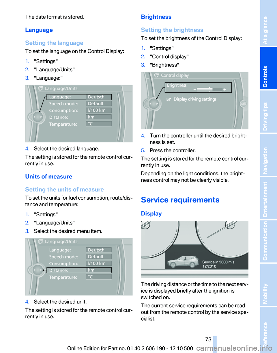
To set the language on the Control Display:1."Settings"2."Language/Units"3."Language:"4.Select the desired language.
The setting is stored for the remote control cur‐
rently in use.
Units of measure
Setting the units of measure
To set the units for fuel consumption, route/dis‐
tance and temperature:
1."Settings"2."Language/Units"3.Select the desired menu item.4.Select the desired unit.
The setting is stored for the remote control cur‐
rently in use.
Brightness
Setting the brightness
To set the brightness of the Control Display:1."Settings"2."Control display"3."Brightness"4.Turn the controller until the desired bright‐
ness is set.5.Press the controller.
The setting is stored for the remote control cur‐
rently in use.
Depending on the light conditions, the bright‐
ness control may not be clearly visible.
Service requirements
Display
The driving distance or the time to the next serv‐
ice is displayed briefly after the ignition is
switched on.
The current service requirements can be read
out from the remote control by the service spe‐
cialist.
Seite 7373
Online Edition for Part no. 01 40 2 606 190 - 12 10 500
ReferenceMobilityCommunicationEntertainmentNavigationDriving tipsControlsAt a glance
Page 75 of 262

Several of the lamps are checked for proper
functioning and light up temporarily when the
engine is started or the ignition is switched on.
Text messages
Text messages in combination with a symbol in
the instrument cluster explain a Check Control
message and the meaning of the indicator and
warning lamps.
Supplementary text messages
Addition information, such as on the cause of a
fault or the required action, can be called up via
Check Control. The supplementary text of ur‐
gent messages is displayed automatically.
It is shown on the Control Display.
Hiding Check Control messages
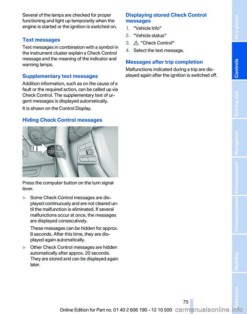
Press the computer button on the turn signal
lever.
▷Some Check Control messages are dis‐
played continuously and are not cleared un‐
til the malfunction is eliminated. If several
malfunctions occur at once, the messages
are displayed consecutively.
These messages can be hidden for approx.
8 seconds. After this time, they are dis‐
played again automatically.▷Other Check Control messages are hidden
automatically after approx. 20 seconds.
They are stored and can be displayed again
later.Displaying stored Check Control
messages1."Vehicle Info"2."Vehicle status"3. "Check Control"4.Select the text message.
Messages after trip completion
Malfunctions indicated during a trip are dis‐
played again after the ignition is switched off.
Seite 7575
Online Edition for Part no. 01 40 2 606 190 - 12 10 500
ReferenceMobilityCommunicationEntertainmentNavigationDriving tipsControlsAt a glance
Page 77 of 262

The setting is stored for the remote control cur‐
rently in use.
Automatic headlamp control
Switch position
: the low beams are switched
on and off automatically, e.g., in tunnels, in twi‐
light or if there is precipitation. The indicator
lamp in the instrument cluster lights up.
A blue sky with the sun low on the horizon can
cause the lights to be switched on.
The low beams always stay on when the fog
lamps are switched on.
Personal responsibility
The automatic headlamp control cannot
serve as a substitute for your personal judgment
in determining when the lamps should be
switched on in response to ambient lighting
conditions.
For example, the sensors are unable to detect
fog or hazy weather. To avoid safety risks, you
should always switch on the lamps manually un‐
der these conditions.◀
Daytime running lights*
The daytime running lights light up in posi‐
tion 0,
and . After the ignition is
switched off, the parking lamps light up in posi‐
tion
.
Activating/deactivating
1."Settings"2."Lighting"3."Daytime running lamps"
The setting is stored for the remote control cur‐
rently in use.
Roadside parking lamps
The vehicle can be illuminated on one side.
Switching on
With the ignition switched off, press the lever
either up or down past the resistance point for
approx. 2 seconds.
Switching off
Briefly press the lever to the resistance point in
the opposite direction.
Adaptive light control*
The concept
Adaptive light control is a variable headlamp
control system that enables dynamic illumina‐
tion of the road surface.
Depending on the steering angle and other pa‐
rameters, the light from the headlamp follows
the course of the road.
In tight curves, e.g., on mountainous roads or
when turning, an additional, corner-illuminating
lamp is switched on that lights up the inside of
the curve when the vehicle is moving below a
certain speed.
Controls
Activating
Switch position
with the ignition switched
on.
The turning lamps are automatically switched
on depending on the steering angle or the use
of turn signals.
Seite 7777
Online Edition for Part no. 01 40 2 606 190 - 12 10 500
ReferenceMobilityCommunicationEntertainmentNavigationDriving tipsControlsAt a glance
Page 79 of 262

▷When the windshield in front of the interior
rearview mirror is fogged over, dirty or cov‐
ered with stickers, etc.
Camera
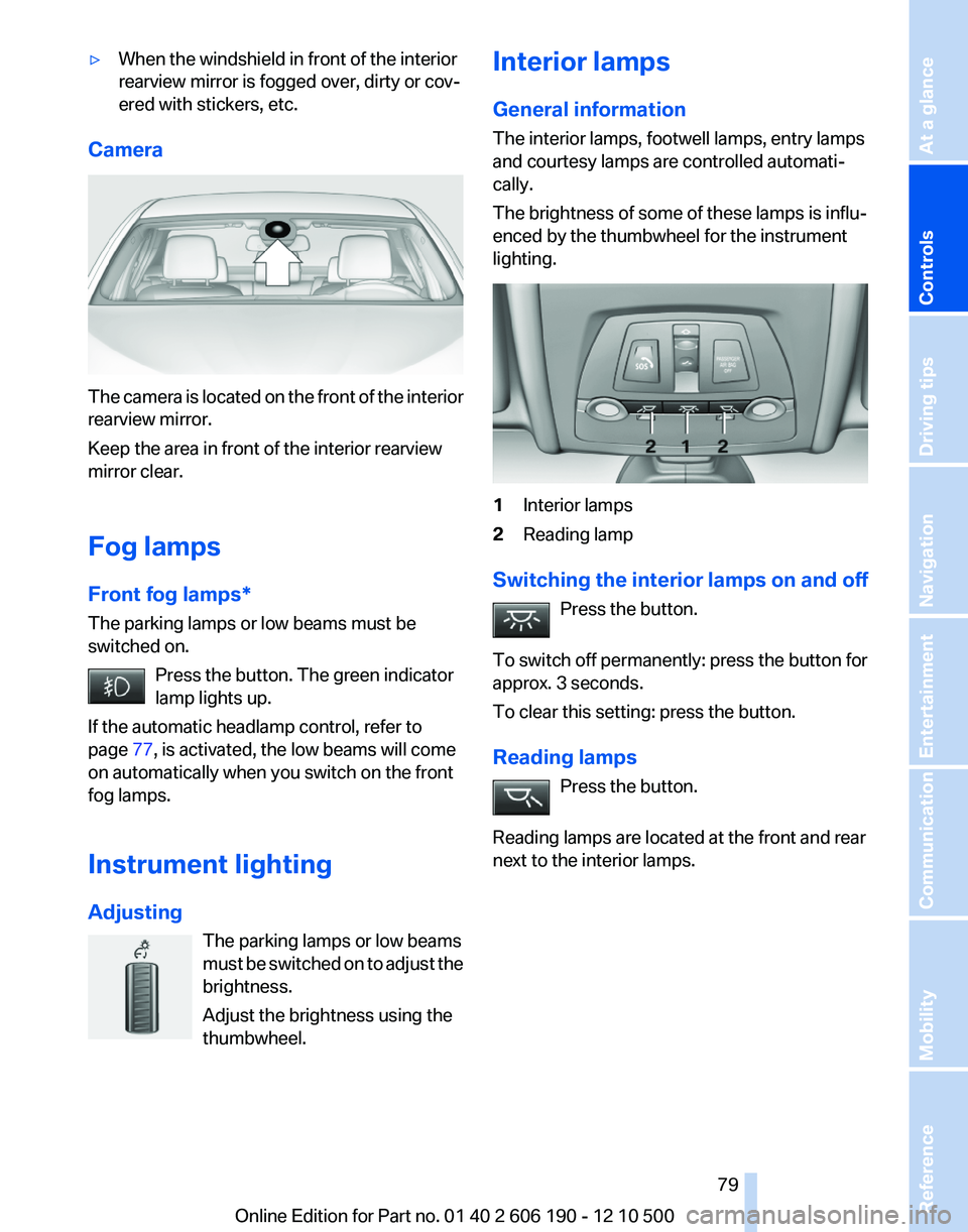
The camera is located on the front of the interior
rearview mirror.
Keep the area in front of the interior rearview
mirror clear.
Fog lamps
Front fog lamps*
The parking lamps or low beams must be
switched on.
Press the button. The green indicator
lamp lights up.
If the automatic headlamp control, refer to
page 77, is activated, the low beams will come
on automatically when you switch on the front
fog lamps.
Instrument lighting
Adjusting The parking lamps or low beams
must be switched on to adjust the
brightness.
Adjust the brightness using the
thumbwheel.
Interior lamps
General information
The interior lamps, footwell lamps, entry lamps
and courtesy lamps are controlled automati‐
cally.
The brightness of some of these lamps is influ‐
enced by the thumbwheel for the instrument
lighting.1Interior lamps2Reading lamp
Switching the interior lamps on and off
Press the button.
To switch off permanently: press the button for
approx. 3 seconds.
To clear this setting: press the button.
Reading lamps Press the button.
Reading lamps are located at the front and rear
next to the interior lamps.
Seite 7979
Online Edition for Part no. 01 40 2 606 190 - 12 10 500
ReferenceMobilityCommunicationEntertainmentNavigationDriving tipsControlsAt a glance
Page 81 of 262

▷Keep the dashboard and window on the
front passenger side clear, i.e., do not cover
with adhesive labels or coverings, and do not
attach holders such as for navigation instru‐
ments and mobile phones.▷Make sure that the front passenger is sitting
correctly, i.e., keeps his or her feet and legs
in the footwell; otherwise, leg injuries can
occur if the front airbag is triggered.▷Do not place slip covers, seat cushions or
other objects on the front passenger seat
that are not approved specifically for seats
with integrated side airbags.▷Do not hang pieces of clothing, such as jack‐
ets, over the backrests.▷Make sure that occupants keep their heads
away from the side airbag and do not rest
against the head airbag; otherwise, injuries
can occur if the airbags are triggered.▷Do not remove the airbag restraint system.▷Do not remove the steering wheel.▷Do not apply adhesive materials to the air‐
bag cover panels, cover them or modify
them in any way.▷Never modify either the individual compo‐
nents or the wiring in the airbag system. This
also applies to steering wheel covers, the
dashboard, the seats, the roof pillars and the
sides of the headliner.◀
Even when all instructions are followed closely,
injury from contact with the airbags cannot be
ruled out in certain situations.
The ignition and inflation noise may lead to
short-term and, in most cases, temporary hear‐
ing impairment in sensitive individuals.
In the case of a malfunction, deactivation
and after triggering of the airbags
Do not touch the individual components imme‐
diately after the system has been triggered; oth‐
erwise, there is the danger of burns.
Only have the airbags checked, repaired or dis‐
mantled and the airbag generator scrapped by
your service center or a workshop that has the
necessary authorization for handling explosives.
Non-professional attempts to service the sys‐
tem could lead to failure in an emergency or un‐
desired triggering of the airbag, either of which
could result in injury.◀
Warnings and information on the airbags are
also found on the sun visors.
Automatic deactivation of the front
passenger airbags
The system determines whether the front pas‐
senger seat is occupied by measuring the re‐
sistance of the human body.
The front, knee, and side airbag on the front
passenger side are activated or deactivated ac‐
cordingly.
Leave feet in the footwell
Make sure that the front passenger keeps
his or her feet in the footwell; otherwise, the front
passenger airbags may not function properly.◀
Child restraint fixing system in the front
passenger seat
Before transporting a child on the front passen‐
ger seat, see the safety notes and instructions
under Children on the front passenger seat.◀
Malfunction of the automatic
deactivation system
When transporting older children and adults, the
front passenger airbags may be deactivated in
certain sitting positions. In this case, the indica‐
tor lamp for the front passenger airbags lights
up.
In this case, change the sitting position so that
the front passenger airbags are activated and
the indicator lamp goes out.
If it is not possible to activate the airbags, have
the person sit in the rear.
To make sure that the occupied seat cushion
can be evaluated correctly▷Do not attach covers, cushions, ball mats or
other items to the front passenger seat un‐
less they are specifically recommended by
the manufacturer of your vehicle.Seite 8181
Online Edition for Part no. 01 40 2 606 190 - 12 10 500
ReferenceMobilityCommunicationEntertainmentNavigationDriving tipsControlsAt a glance
Page 83 of 262

System limitsSudden tire damage
Sudden serious tire damage caused by
external influences cannot be indicated in ad‐
vance.◀
The system does not operate correctly if it has
not been reset. For example, a flat tire may be
indicated despite correct tire inflation pres‐
sures.
The system is inactive and cannot indicate a flat
tire:▷For a mounted wheel without TPM electron‐
ics.▷When the TPM is disturbed by other sys‐
tems or devices with the same radio fre‐
quency.
Status display
The current status of the Tire Pressure Monitor
TPM can be displayed on the Control Display,
e.g., whether or not the TPM is active.
1."Vehicle Info"2."Vehicle status"3. "Tire Pressure Monitor - TPM"
The status is displayed.
Resetting the system
Reset the system after each correction of the
tire inflation pressure and after every tire or
wheel change.
1."Vehicle Info"2."Vehicle status"3. "Reset TPM"4.Start the engine - do not drive away.5.Reset the tire pressure using "Reset".6.Drive away.
The tires are shown in gray and "Resetting
TPM..." is displayed.
After driving for a few minutes, the set tire infla‐
tion pressures are applied as set values. The re‐
setting process is completed automatically dur‐
ing driving. The tires are shown in green and
"TPM active" is shown on the Control Display.
The trip can be interrupted at any time. If you
drive away again, the process resumes auto‐
matically.
If a flat tire is detected during a reset, all tires are
displayed in yellow.
Low tire pressure message The yellow warning lamp lights up. A
Check Control message is displayed.▷There is a flat tire or a major loss in
tire inflation pressure.▷The system was not reset after a wheel
change and thus warns based on the infla‐
tion pressures initialized last.1.Reduce your speed and stop cautiously.
Avoid sudden braking and steering maneu‐
vers.2.Check whether the vehicle is fitted with reg‐
ular tires* or run-flat tires*.
Run-flat tires, refer to page 213, are labeled
with a circular symbol containing the letters
RSC marked on the tire sidewall.
When a low inflation pressure is indicated, DSC
Dynamic Stability Control is switched on if nec‐
essary.
Actions in the event of a flat tire
Normal tires*
1.Identify the damaged tire.
Do this by checking the air pressure in all
four tires.
If the tire inflation pressure in all four tires is
correct, the Tire Pressure Monitor may not
have been initialized. In this case, initialize
the system.
If an identification is not possible, please
contact the service center.2.Rectify the flat tire on the damaged wheel.
Use of tire sealant, e.g., the Mobility System,
may damage the TPM wheel electronics. In
this case, have the electronics checked atSeite 8383
Online Edition for Part no. 01 40 2 606 190 - 12 10 500
ReferenceMobilityCommunicationEntertainmentNavigationDriving tipsControlsAt a glance
Page 85 of 262

the vehicle manufacturer on the vehicle placard
or tire inflation pressure label. (If your vehicle has
tires of a different size than the size indicated on
the vehicle placard or tire inflation pressure la‐
bel, you should determine the proper tire infla‐
tion pressure for those tires.) As an added safety
feature, your vehicle has been equipped with a
tire pressure monitoring system (TPMS) that il‐
luminates a low tire pressure telltale when one
or more of your tires is significantly under-in‐
flated. Accordingly, when the low tire pressure
telltale illuminates, you should stop and check
your tires as soon as possible, and inflate them
to the proper pressure. Driving on a significantly
under-inflated tire causes the tire to overheat
and can lead to tire failure. Under-inflation also
reduces fuel efficiency and tire tread life, and
may affect the vehicle's handling and stopping
ability. Please note that the TPMS is not a sub‐
stitute for proper tire maintenance, and it is the
driver's responsibility to maintain correct tire
pressure, even if under-inflation has not reached
the level to trigger illumination of the TPMS low
tire pressure telltale. Your vehicle has also been
equipped with a TPMS malfunction indicator to
indicate when the system is not operating prop‐
erly. The TPMS malfunction indicator is com‐
bined with the low tire pressure telltale. When
the system detects a malfunction, the telltale will
flash for approximately one minute and then re‐
main continuously illuminated. This sequence
will continue upon subsequent vehicle start-ups
as long as the malfunction exists. When the mal‐
function indicator is illuminated, the system may
not be able to detect or signal low tire pressure
as intended. TPMS malfunctions may occur for
a variety of reasons, including the installation of
replacement or alternate tires or wheels on the
vehicle that prevent the TPMS from functioning
properly. Always check the TPMS malfunction
telltale after replacing one or more tires or
wheels on your vehicle to ensure that the re‐
placement or alternate tires and wheels allow
the TPMS to continue to function properly.Brake force display*
The concept▷During normal brake application, the outer
brake lamps light up.▷During heavy brake application, the inner
brake lamps light up in addition.Seite 8585
Online Edition for Part no. 01 40 2 606 190 - 12 10 500
ReferenceMobilityCommunicationEntertainmentNavigationDriving tipsControlsAt a glance
Page 87 of 262

The system ensures maximum forward momen‐
tum on special road conditions, e.g., unplowed
snowy roads, but driving stability is limited.
It is therefore necessary to drive with appropri‐
ate caution.
You may find it useful to briefly activate DTC un‐
der the following special circumstances:▷When driving in slush or on uncleared,
snow-covered roads.▷When rocking the vehicle or driving off in
deep snow or on loose surfaces.▷When driving with snow chains.
Deactivating/activating DTC Dynamic
Traction Control
Activating the Dynamic Traction Control DTC
provides maximum traction on loose ground.
Driving stability is limited during acceleration
and when driving in bends.
Activating DTC Press the button.
TRACTION is displayed in the instru‐
ment cluster and the indicator lamp for DSC
lights up.
Deactivating DTC Press the button again.
TRACTION and the DSC indicator lamp
go out.
Performance Control*
Performance Control enhances the agility of
your vehicle.
To enhance performance during sporty driving,
the rear wheel on the inside of the curve is
braked while the resulting braking effect is
largely compensated by engine intervention.
xDrive
xDrive is the all-wheel-drive system of your ve‐
hicle. Concerted action by the xDrive and DSC
further optimize traction and driving dynamics.
The xDrive all-wheel-drive system variably dis‐
tributes the drive forces to the front and rear
axles as demanded by the driving situation and
road surface.
HDC Hill Descent Control
The concept
HDC is a downhill driving assistant that auto‐
matically controls vehicle speed on steep down‐
hill gradients. Without requiring brake applica‐
tion, the vehicle moves at slightly more than
twice walking speed.
You can activate the Hill Descent Control at
speeds below approx. 22 mph/35 km/h. When
driving downhill, the vehicle reduces its speed
to approx. twice walking speed and then keeps
its speed constant.
While you are actively braking, the system is on
standby. The system does not brake the vehicle
during this time.
Use HDC in low gears or in transmission position
D or R only.
Changing the speed
The speed can be changed in the range from
roughly twice walking speed to approx. 15 mph/
25 km/h by lightly pressing the accelerator.
To set the speed: buttons* on the
steering wheel
The desired speed can be specified in the range
from roughly twice walking speed to approx.
15 mph/25 km/h using the rocker switch of the
cruise control on the steering wheel.Seite 8787
Online Edition for Part no. 01 40 2 606 190 - 12 10 500
ReferenceMobilityCommunicationEntertainmentNavigationDriving tipsControlsAt a glance