2011 BMW 550I speed
[x] Cancel search: speedPage 66 of 304

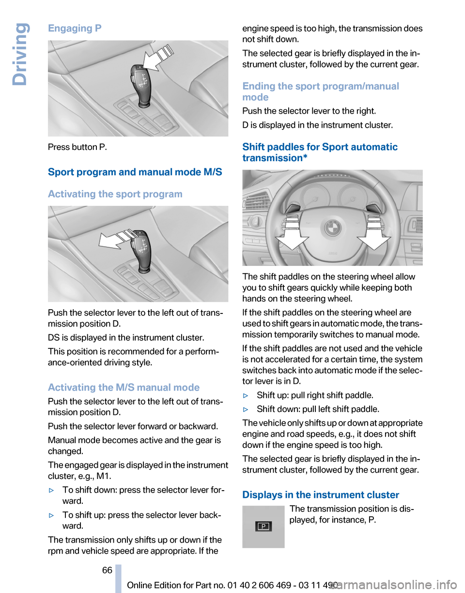
Engaging P
Press button P.
Sport program and manual mode M/S
Activating the sport program
Push the selector lever to the left out of trans‐
mission position D.
DS is displayed in the instrument cluster.
This position is recommended for a perform‐
ance-oriented driving style.
Activating the M/S manual mode
Push the selector lever to the left out of trans‐
mission position D.
Push the selector lever forward or backward.
Manual mode becomes active and the gear is
changed.
The
engaged gear is displayed in the instrument
cluster, e.g., M1.
▷ To shift down: press the selector lever for‐
ward.
▷ To shift up: press the selector lever back‐
ward.
The transmission only shifts up or down if the
rpm and vehicle speed are appropriate. If the engine speed is too high, the transmission does
not shift down.
The selected gear is briefly displayed in the in‐
strument cluster, followed by the current gear.
Ending the sport program/manual
mode
Push the selector lever to the right.
D is displayed in the instrument cluster.
Shift paddles for Sport automatic
transmission*
The shift paddles on the steering wheel allow
you to shift gears quickly while keeping both
hands on the steering wheel.
If the shift paddles on the steering wheel are
used
to shift gears in automatic mode, the trans‐
mission temporarily switches to manual mode.
If the shift paddles are not used and the vehicle
is not accelerated for a certain time, the system
switches back into automatic mode if the selec‐
tor lever is in D.
▷ Shift up: pull right shift paddle.
▷ Shift down: pull left shift paddle.
The vehicle only shifts up or down at appropriate
engine and road speeds, e.g., it does not shift
down if the engine speed is too high.
The selected gear is briefly displayed in the in‐
strument cluster, followed by the current gear.
Displays in the instrument cluster The transmission position is dis‐
played, for instance, P. Seite 66
66 Online Edition for Part no. 01 40 2 606 469 - 03 11 490
Driving
Page 67 of 304

Displays
Instrument cluster
Overview, instrument cluster
1
Fuel gauge 72
2 Speedometer
3 Indicator/warning lamps 70
4 Tachometer 72 5
Engine oil temperature 72
6 Electronic displays 69
7 Display/reset miles 73
Seite 67
67Online Edition for Part no. 01 40 2 606 469 - 03 11 490
Reference Mobility Communication Entertainment Navigation Driving tips
Controls At a glance
Page 68 of 304

Overview, instrument cluster with enhanced features*
1
Fuel gauge 72
2 Speedometer
3 Indicator/warning lamps 70
4 Tachometer 72 5
Engine oil temperature 72
6 Electronic displays 69
7 Display/reset miles 73
Seite 68
68 Online Edition for Part no. 01 40 2 606 469 - 03 11 490Displays
Page 72 of 304

▷ "Service request"
Contact the service partner.
▷ "Roadside Assistance"
Contact Roadside Assistance.
Hiding Check Control messages Press the computer button on the turn signal
lever.
▷
Some Check Control messages are dis‐
played
continuously and are not cleared un‐
til the malfunction is eliminated. If several
malfunctions occur at once, the messages
are displayed consecutively.
These messages can be hidden for approx.
8 seconds. After this time, they are dis‐
played again automatically.
▷ Other Check Control messages are hidden
automatically after approx. 20 seconds.
They
are stored and can be displayed again
later.
Displaying stored Check Control
messages
1. "Vehicle Info"
2. "Vehicle status"
3. "Check Control"
4. Select the text message.
Messages after trip completion
Malfunctions indicated during a trip are dis‐
played again after the ignition is switched off. Fuel gauge
The vehicle inclination may
cause the display to vary.
Notes on refueling, refer to
page 240.
Tachometer Always avoid engine speeds in the red warning
field.
In this range, the fuel supply is interrupted
to protect the engine.
Engine oil temperature
▷Cold engine: the pointer is at
the low temperature end.
Drive
at moderate engine and
vehicle speeds.
▷ Normal operating tempera‐
ture:
the pointer is in the mid‐
dle or in the left half of the
temperature display.
▷ Hot engine: the pointer is at the high tem‐
perature end. A Check Control message is
displayed in addition.
Coolant temperature
Should the coolant, and with it the engine, be‐
come too hot, a Check Control message is dis‐
played.
Check the coolant level, refer to page 258. Seite 72
72 Online Edition for Part no. 01 40 2 606 469 - 03 11 490
Displays
Page 76 of 304

Calling up information on the info
display
Press the computer button on the turn signal
lever.
Information
is displayed on the info display of the
instrument cluster.
Information at a glance
Repeatedly pressing the button on the turn sig‐
nal lever calls up the following information on the
info display:
▷ Range.
▷ Average fuel consumption.
▷ Average speed.
▷ Date*.
▷ Time of arrival*
When destination guidance is activated in
the navigation system.
▷ Distance to destination*
When destination guidance is activated in
the navigation system.
▷ Arrow view of navigation system*
When destination guidance is activated in
the navigation system.
Adjusting the info display
You can select what information from the com‐
puter
is to be displayed on the info display of the
instrument cluster.
1. "Settings"
2. "Info display" 3.
Select the desired displays. Information in detail
Range
Displays the estimated cruising range available
with the remaining fuel.
It is calculated based on your driving style over
the last 20 miles/30 km.
If there is only enough fuel left for less than
45
miles/80 km, the color of the display changes.
Average fuel consumption
This is calculated for the period during which the
engine is running.
The average fuel consumption is calculated on
the basis of various distances.
Average speed
Periods in which the vehicle is parked with the
engine stopped do not enter into the calculation.
Resetting average values
Press and hold the computer button on the turn
signal lever.
Distance to destination*
The distance remaining to the destination is dis‐
played if a destination is entered in the naviga‐
tion system* before the trip is started.
The distance to the destination is adopted au‐
tomatically.
Seite 76
76 Online Edition for Part no. 01 40 2 606 469 - 03 11 490
Displays
Page 77 of 304

Time of arrival*
The estimated time of arrival is
displayed if a destination is en‐
tered in the navigation system
*
before the trip is started.
The time must be correctly set.
Speed limit
Display of a speed limit which, when reached,
should cause a warning to be issued.
Renewed warning if the vehicle speed drops be‐
low the set speed limit once by at least 3 mph/
5 km/h.
Displaying, setting or changing the
limit
1. "Settings"
2. "Speed"
3. "Warning at:" 4.
Turn the controller until the desired limit is
displayed.
5. Press the controller.
The speed limit is stored.
Activating/deactivating the limit
1. "Settings"
2. "Speed"
3. "Warning"
4. Press the controller.
Applying your current speed as the
limit
1. "Settings"
2. "Speed" 3.
"Select current speed"
4. Press the controller.
The current vehicle speed is stored as the
limit.
Resetting values
The average fuel consumption and average
speed can be reset.
Press
and hold the computer button on the turn
signal lever.
Trip computer
There are two types of computer.
▷ "Onboard info": the values can be reset as
often as necessary.
▷ "Trip
computer": the values provide an over‐
view of the current trip.
Resetting the trip computer
1. "Vehicle Info"
2. "Trip computer"
3. "Reset": all values are reset.
"Automatically reset": all values are reset
approx.
4 hours after the vehicle comes to a
standstill. Display on the Control Display
Display the computer or trip computer on the
Control Display.
1.
"Vehicle Info"
2. "Onboard info" or "Trip computer"
Seite 77
77Online Edition for Part no. 01 40 2 606 469 - 03 11 490
Reference Mobility Communication Entertainment Navigation Driving tips
Controls At a glance
Page 78 of 304

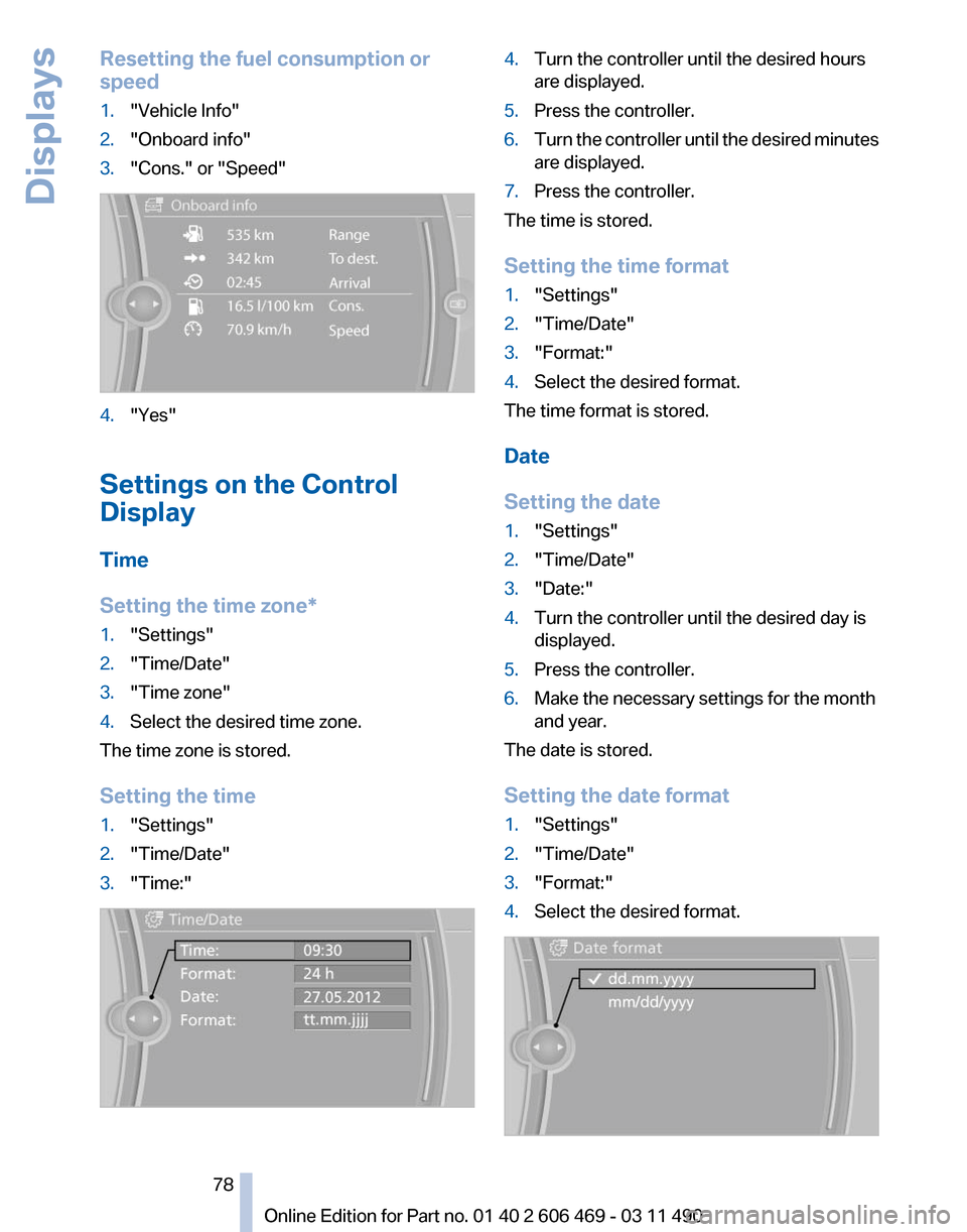
Resetting the fuel consumption or
speed
1.
"Vehicle Info"
2. "Onboard info"
3. "Cons." or "Speed" 4.
"Yes"
Settings on the Control
Display
Time
Setting the time zone
*
1. "Settings"
2. "Time/Date"
3. "Time zone"
4. Select the desired time zone.
The time zone is stored.
Setting the time
1. "Settings"
2. "Time/Date"
3. "Time:" 4.
Turn the controller until the desired hours
are displayed.
5. Press the controller.
6. Turn the controller until the desired minutes
are displayed.
7. Press the controller.
The time is stored.
Setting the time format
1. "Settings"
2. "Time/Date"
3. "Format:"
4. Select the desired format.
The time format is stored.
Date
Setting the date
1. "Settings"
2. "Time/Date"
3. "Date:"
4. Turn the controller until the desired day is
displayed.
5. Press the controller.
6. Make the necessary settings for the month
and year.
The date is stored.
Setting the date format
1. "Settings"
2. "Time/Date"
3. "Format:"
4. Select the desired format. Seite 78
78 Online Edition for Part no. 01 40 2 606 469 - 03 11 490
Displays
Page 81 of 304

The setting is stored for the remote control cur‐
rently in use.
Automatic headlamp control
Switch
position : the low beams are switched
on and off automatically, e.g., in tunnels, in twi‐
light or if there is precipitation. The indicator
lamp in the instrument cluster lights up.
A blue sky with the sun low on the horizon can
cause the lights to be switched on.
The low beams always stay on when the fog
lamps are switched on.
Personal responsibility
The automatic headlamp control cannot
serve
as a substitute for your personal judgment
in determining when the lamps should be
switched on in response to ambient lighting
conditions.
For example, the sensors are unable to detect
fog or hazy weather. To avoid safety risks, you
should always switch on the lamps manually un‐
der these conditions.◀
Daytime running lights*
With the ignition switched on, the daytime run‐
ning lights light up in position 0, or .
After the ignition is switched off, the parking
lamps light up in position
.
Activating/deactivating
1. "Settings"
2. "Lighting"
3. "Daytime running lamps" The setting is stored for the remote control cur‐
rently in use. Roadside parking lamps
The vehicle can be illuminated on one side.
Switching on
With the ignition switched off, press the lever
either up or down past the resistance point for
approx. 2 seconds.
Switching off
Briefly press the lever to the resistance point in
the opposite direction.
Adaptive light control*
The concept
Adaptive light control is a variable headlamp
control system that enables dynamic illumina‐
tion of the road surface.
Depending on the steering angle and other pa‐
rameters, the light from the headlamp follows
the course of the road.
In tight curves, e.g., on mountainous roads or
when turning, an additional, corner-illuminating
lamp is switched on that lights up the inside of
the curve when the vehicle is moving below a
certain speed.
Controls
Activating
Switch position
with the ignition switched
on.
The turning lamps are automatically switched
on depending on the steering angle or the use
of turn signals.
Seite 81
81Online Edition for Part no. 01 40 2 606 469 - 03 11 490
Reference Mobility Communication Entertainment Navigation Driving tips
Controls At a glance