Page 57 of 86

PERIODIC MAINTENANCE AND ADJUSTMENT
7-13
7 5. Clean the sponge material with
solvent, and then squeeze the re-
maining solvent out.
6. Apply oil of the recommended type
to the entire surface of the sponge
material, and then squeeze the ex-
cess oil out.
TIPThe sponge material should be wet but
not dripping.7. Pull the sponge material over the
air filter element frame.
8. Insert the air filter element into the
air filter case with the projection
facing upward, and then install the
washer and wing bolt. NOTICE:
Make sure that the air filter ele-
ment is properly seated in the
air filter case. The engine
should never be operated with-
out the air filter element in-
stalled, otherwise the piston(s)
and/or cylinder(s) may become
excessively worn.
[ECA10481]
9. Install the air filter case cover in the
original position as shown.
10. Install the seat.
1. Sponge material
2. Air filter element frame
Recommended oil:
Yamaha foam air filter oil or other
quality foam air filter oil
1. Air filter element
2. Projection
U5PA88E0.book Page 13 Tuesday, June 9, 2009 8:44 AM
Page 58 of 86

PERIODIC MAINTENANCE AND ADJUSTMENT
7-14
7
EAU42110
Adjusting the carburetor The carburetor is an important part of
the engine and requires very sophisti-
cated adjustment. Therefore, most car-
buretor adjustments should be left to a
Yamaha dealer, who has the neces-
sary professional knowledge and expe-
rience. The adjustment described in the
following section, however, may be ser-
viced by the owner as part of routine
maintenance.NOTICE
ECA10550
The carburetor has been set and ex-
tensively tested at the Yamaha fac-
tory. Changing these settings
without sufficient technical knowl-
edge may result in poor perfor-
mance of or damage to the engine.
EAU44390
Adjusting the engine idling
speed The engine idling speed must be ad-
justed when necessary.
1. Start the engine and thoroughly
warm it up.
2. Turn the throttle stop screw until
the engine runs at the lowest pos-
sible speed.
3. To increase the engine idling
speed, turn the throttle stop screw
in direction (a). To decrease the
engine idling speed, turn the throt-
tle stop screw in direction (b).
EAU21370
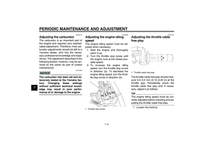
Adjusting the throttle cable
free play The throttle cable free play should mea-
sure 3.0–5.0 mm (0.12–0.20 in) at the
throttle grip. Periodically check the
throttle cable free play and, if neces-
sary, adjust it as follows.TIPThe engine idling speed must be cor-
rectly adjusted before checking and ad-
justing the throttle cable free play.1. Loosen the locknut.
1. Throttle stop screw
1. Throttle cable free play
U5PA88E0.book Page 14 Tuesday, June 9, 2009 8:44 AM
Page 59 of 86
. To decrease the throttle
cable free play, turn the adjusting
nut in d")
PERIODIC MAINTENANCE AND ADJUSTMENT
7-15
7 2. To increase the throttle cable free
play, turn the adjusting nut in direc-
tion (a). To decrease the throttle
cable free play, turn the adjusting
nut in direction (b).
3. Tighten the locknut.
EAU41821
Tires To maximize the performance, durabil-
ity, and safe operation of your motorcy-
cle, note the following points regarding
the specified tires.
Tire air pressure
The tire air pressure should be checked
and, if necessary, adjusted before each
ride.
WARNING
EWA14381
Operation of this vehicle with im-
proper tire pressure may cause se-
vere injury or death from loss of
control.�
The tire air pressure must be
checked and adjusted on cold
tires (i.e., when the temperature
of the tires equals the ambient
temperature).
�
The tire air pressure must be ad-
justed in accordance with the
weight of the rider, the riding
speed, and the riding condi-
tions.
Tire inspection
The tires must be checked before each
ride.NOTICE
ECA15580
�
Be sure the bead stoppers are
tightened. Loose bead stoppers
will cause the tire to slip off the
rim if tire pressure is too low.
1. Locknut
2. Throttle cable free play adjusting nut
Standard tire air pressure:
Front:
100 kPa (1.00 kgf/cm², 15 psi)
Rear:
100 kPa (1.00 kgf/cm², 15 psi)
1. Tire sidewall
2. Tire tread depth
12
U5PA88E0.book Page 15 Tuesday, June 9, 2009 8:44 AM
Page 60 of 86

PERIODIC MAINTENANCE AND ADJUSTMENT
7-16
7
�
Be sure the valve stem is posi-
tioned straight. A tilted valve
stem indicates that the tire has
slipped from its original posi-
tion on the rim. Rotate the tire
so that the valve stem is posi-
tioned straight.
If the center tread depth reaches the
specified limit, if the tire has a nail or
glass fragments in it, or if the sidewall is
cracked, have a Yamaha dealer re-
place the tire immediately.
Tire information
This motorcycle is equipped with spoke
wheels and tube tires.
WARNING
EWA10461
The front and rear tires should be of
the same make and design, other-
wise the handling characteristics of
the vehicle may be different, which
could lead to an accident.
After extensive tests, only the tires list-
ed below have been approved for this
model by Yamaha Motor Co., Ltd.
WARNING
EWA14390
�
Have a Yamaha dealer replace
excessively worn tires. Operat-
ing the motorcycle with exces-
sively worn tires decreases
riding stability and can lead to
loss of control.
�
The replacement of all wheel-
and brake-related parts, includ-
ing the tires, should be left to a
Yamaha dealer, who has the
necessary professional knowl-
edge and experience.
�
It is not recommended to patch
a punctured tube. If unavoid-
able, however, patch the tube
very carefully and replace it as
soon as possible with a high-
quality product.
Minimum tire tread depth (front and
rear):
4.0 mm (0.16 in)
Front tire:
Size:
YZ85 70/100-17 40M
YZ85LW 70/100-19 42M
YZ85LWZ 70/100-19 42M
YZ85Z 70/100-17 40M
Manufacturer/model:
YZ85 DUNLOP/D739FA (ZAF)
YZ85 DUNLOP/D756F
(AUT)(BEL)(CHE)(DEU)(DNK)(ES
P)(FIN)(FRA)(GBR)(GRC)(IRL)(IT
A)(NLD)(NOR)(POL)(PRT)(SVN)(
SWE)
YZ85LW DUNLOP/D739FA (ZAF)
YZ85LW DUNLOP/D756F
(AUT)(BEL)(CHE)(DEU)(DNK)(ES
P)(FIN)(FRA)(GBR)(GRC)(IRL)(IT
A)(NLD)(NOR)(POL)(PRT)(SVN)(
SWE)
YZ85LWZ DUNLOP/D756F
YZ85Z DUNLOP/D756F
Rear tire:
Size:
YZ85 90/100-14 49M
YZ85LW 90/100-16 52M
YZ85LWZ 90/100-16 52M
YZ85Z 90/100-14 49M
Manufacturer/model:
DUNLOP/D756
U5PA88E0.book Page 16 Tuesday, June 9, 2009 8:44 AM
Page 61 of 86

PERIODIC MAINTENANCE AND ADJUSTMENT
7-17
7
EAU48320
Spoke wheels
WARNING
EWA10610
The wheels on this model are not de-
signed for use with tubeless tires.
Do not attempt to use tubeless tires
on this model.To maximize the performance, durabil-
ity, and safe operation of your motorcy-
cle, note the following points regarding
the specified wheels.�
The wheel rims should be checked
for cracks, bends or warpage, and
the spokes for looseness or dam-
age before each ride. If any dam-
age is found, have a Yamaha
dealer replace the wheel. Do not
attempt even the smallest repair to
the wheel. A deformed or cracked
wheel must be replaced.
�
The wheel should be balanced
whenever either the tire or wheel
has been changed or replaced. An
unbalanced wheel can result in
poor performance, adverse han-
dling characteristics, and a short-
ened tire life.
EAU22034
Adjusting the clutch lever free
play The clutch lever free play should mea-
sure 10.0–15.0 mm (0.39–0.59 in) as
shown. Periodically check the clutch le-
ver free play and, if necessary, adjust it
as follows.
1. Slide the rubber cover back at the
clutch lever.
2. Loosen the locknut.
3. To increase the clutch lever free
play, turn the clutch lever free play
adjusting bolt in direction (a). Todecrease the clutch lever free play,
turn the adjusting bolt in direction
(b).
TIPIf the specified clutch lever free play
could be obtained as described above,
skip steps 4–7.4. Fully turn the adjusting bolt in di-
rection (a) to loosen the clutch ca-
ble.
5. Loosen the locknut further down
the clutch cable.
6. To increase the clutch lever free
play, turn the clutch lever free play
adjusting nut in direction (a). To
1. Clutch lever free play
2. Locknut (clutch lever)
3. Clutch lever free play adjusting bolt
4. Rubber cover
1
(a) 23
4
1. Locknut (clutch cable)
2. Clutch lever free play adjusting nut (clutch
cable)
U5PA88E0.book Page 17 Tuesday, June 9, 2009 8:44 AM
Page 62 of 86
PERIODIC MAINTENANCE AND ADJUSTMENT
7-18
7decrease the clutch lever free play,
turn the adjusting nut in direction
(b).
7. Tighten the locknut at the clutch
cable.
8. Tighten the locknut at the clutch le-
ver, and then slide the rubber cov-
er to its original position.
EAU37912
Checking the front brake lever
free play There should be no free play at the
brake lever end. If there is free play,
have a Yamaha dealer inspect the
brake system.
WARNING
EWA14211
A soft or spongy feeling in the brake
lever can indicate the presence of air
in the hydraulic system. If there is air
in the hydraulic system, have a
Yamaha dealer bleed the system be-
fore operating the vehicle. Air in the
hydraulic system will diminish thebraking performance, which may re-
sult in loss of control and an acci-
dent.1. No brake lever free play
U5PA88E0.book Page 18 Tuesday, June 9, 2009 8:44 AM
Page 63 of 86

PERIODIC MAINTENANCE AND ADJUSTMENT
7-19
7
EAU44820
Checking the shift pedal The operation of the shift pedal should
be checked before each ride. If opera-
tion is not smooth, have a Yamaha
dealer check the vehicle.
EAU22390
Checking the front and rear
brake pads The front and rear brake pads must be
checked for wear at the intervals spec-
ified in the periodic maintenance and
lubrication chart.
EAU22410
Front brake pads
Each front brake pad is provided with a
wear indicator, which allows you to
check the brake pad wear without hav-
ing to disassemble the brake. To check
the brake pad wear, check the position
of the wear indicator while applying the
brake. If a brake pad has worn to thepoint that the wear indicator almost
touches the brake disc, have a Yamaha
dealer replace the brake pads as a set.
EAU46291
Rear brake pads
Each rear brake pad is provided with
wear indicator grooves, which allow
you to check the brake pad wear with-
out having to disassemble the brake.
To check the brake pad wear, check
the wear indicator grooves. If a brake
pad has worn to the point that a wear
indicator groove almost appears, have
a Yamaha dealer replace the brake
pads as a set.
1. Brake pad wear indicator
1. Brake pad wear indicator groove
U5PA88E0.book Page 19 Tuesday, June 9, 2009 8:44 AM
Page 64 of 86

PERIODIC MAINTENANCE AND ADJUSTMENT
7-20
7
EAU22580
Checking the brake fluid level Front brake
Rear brake
Insufficient brake fluid may allow air to
enter the brake system, possibly caus-
ing it to become ineffective.Before riding, check that the brake fluid
is above the minimum level mark and
replenish if necessary. A low brake fluid
level may indicate worn brake pads
and/or brake system leakage. If the
brake fluid level is low, be sure to check
the brake pads for wear and the brake
system for leakage.
Observe these precautions:
�
When checking the fluid level,
make sure that the top of the brake
fluid reservoir is level.
�
Use only the recommended quality
brake fluid, otherwise the rubber
seals may deteriorate, causing
leakage and poor braking perfor-
mance.
�
Refill with the same type of brake
fluid. Mixing fluids may result in a
harmful chemical reaction and
lead to poor braking performance.
�
Be careful that water does not en-
ter the brake fluid reservoir when
refilling. Water will significantly
lower the boiling point of the fluid
and may result in vapor lock.
�
Brake fluid may deteriorate paint-
ed surfaces or plastic parts. Al-
ways clean up spilled fluid
immediately.
�
As the brake pads wear, it is nor-
mal for the brake fluid level to grad-
ually go down. However, if the
brake fluid level goes down sud-
denly, have a Yamaha dealer
check the cause.
1. Minimum level mark
1. Minimum level mark
Recommended brake fluid:
DOT 4
U5PA88E0.book Page 20 Tuesday, June 9, 2009 8:44 AM


.
7. Tighten the locknut at the clutch
cable.
8. Tighten the locknut at the clutch")