Page 145 of 166
5-39
REAR SHOCK ABSORBER
12 Bearing 2 Refer to removal section. Order Part name Q'ty Remarks
53 Nm (5.3 m kg, 38 ft lb)
56 Nm (5.6 m kg, 40 ft lb)
2 Nm (0.2 m kg, 1.4 ft lb)
32 Nm (3.2 m kg, 23 ft lb)
29 Nm (2.9 m kg, 21 ft lb)
Page 146 of 166

5-40
REAR SHOCK ABSORBER
HANDLING NOTE
• Support the machine securely so
there is no danger of it falling
over.
• This rear shock absorber is pro-
vided with a separate type tank
filled with high-pressure nitro-
gen gas. To prevent the danger
of explosion, read and under-
stand the following information
before handling the shock ab-
sorber. The manufacturer can
not be held responsible for prop-
erty damage or personal injury
that may result from improper
handling.
• Never tamper or attempt to dis-
assemble the cylinder or the
tank.
• Never throw the rear shock ab-
sorber into an open flame or
other high heat. The rear shock
absorber may explode as a re-
sult of nitrogen gas expansion
and/ or damage to the hose.
• Be careful not to damage any
part of the gas tank. A damaged
gas tank will impair the damp-
ing performance or cause a
malfunction.
• Take care not to scratch the
contact surface of the piston
rod with the cylinder; or oil
could leak out.
• Never attempt to remove the
plug at the bottom of the nitro-
gen gas tank. It is very danger-
ous to remove the plug.
• When scrapping the rear shock
absorber, follow the instruc-
tions on disposal.
NOTES ON DISPOSAL (YAMAHA
DEALERS ONLY)
Before disposing the rear shock ab-
sorber, be sure to extract the nitrogen
gas from valve "1". Wear eye protec-
tion to prevent eye damage from es-
caping gas and/or metal chips.
To dispose of a damaged or worn-
out rear shock absorber, take the
unit to your Yamaha dealer for this
disposal procedure.
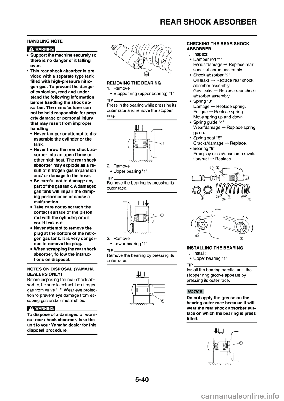
REMOVING THE BEARING
1. Remove:
• Stopper ring (upper bearing) "1"
Press in the bearing while pressing its
outer race and remove the stopper
ring.
2. Remove:
• Upper bearing "1"
Remove the bearing by pressing its
outer race.
3. Remove:
• Lower bearing "1"
Remove the bearing by pressing its
outer race.
CHECKING THE REAR SHOCK
ABSORBER
1. Inspect:
• Damper rod "1"
Bends/damage→Replace rear
shock absorber assembly.
• Shock absorber "2"
Oil leaks→Replace rear shock
absorber assembly.
Gas leaks→Replace rear shock
absorber assembly.
• Spring "3"
Damage→Replace spring.
Fatigue→Replace spring.
Move spring up and down.
• Spring guide "4"
Wear/damage→Replace spring
guide.
• Spring seat "5"
Cracks/damage →Replace.
• Bearing "6"
Free play exists/unsmooth revolu-
tion/rust →Replace.
INSTALLING THE BEARING
1. Install:
• Upper bearing "1"
Install the bearing parallel until the
stopper ring groove appears by
pressing its outer race.
Do not apply the grease on the
bearing outer race because it will
wear the rear shock absorber sur-
face on which the bearing is press
fitted.
Page 147 of 166

5-41
REAR SHOCK ABSORBER
2. Install:
• Stopper ring (upper bearing) "1"
After installing the stopper ring, push
back the bearing until it contacts the
stopper ring.
3. Install:
• Lower bearing "1"
Install the bearing by pressing it on
the side having the manufacture's
marks or numbers.
INSTALLING THE SPRING (REAR
SHOCK ABSORBER)
1. Install:
• Spring "1"
• Upper spring guide "2"
• Lower spring guide "3"
2. Install:
• Spring seat "1"
Install the spring seat with the projec-
tion "a" brought into contact with the
spring end, as shown.
3. Tighten:
•Adjuster "1"
4. Adjust:
• Spring length (installed)
Refer to "ADJUSTING THE
REAR SHOCK ABSORBER
SPRING PRELOAD" section in
the CHAPTER 3.
5. Tighten:
• Locknut "1"
INSTALLING THE REAR SHOCK
ABSORBER
1. Install:
• Dust seal "1"
• O-ring "2"
• Collar "3"
• Apply the molybdenum disulfide
grease on the dust seal lips and col-
lars.
• Apply the lithium soap base grease
on the O-rings.
2. Install:
• Bushing "1"
• Collar "2"
• Dust seal "3"
• Apply the molybdenum disulfide
grease on the bearing and dust seal
lips.
• Install the dust seals with their lips
facing inward.
3. Install:
• Rear shock absorber
4. Install:
• Bolt (rear shock absorber-frame)
"1"
• Washer "2"
• Nut (rear shock absorber-frame)
"3"
Apply the molybdenum disulfide
grease on the bolt.
5. Install:
• Bolt (rear shock absorber-relay
arm) "1"
• Nut (rear shock absorber-relay
arm) "2"
Apply the molybdenum disulfide
grease on the bolt.
Installed depth of the
bearing "a":
4 mm (0.16 in)
Nut (rear shock absorb-
er-frame):
56 Nm (5.6 m•kg, 40
ft•lb)
Nut (rear shock absorb-
er-relay arm):
53 Nm (5.3 m•kg, 38
ft•lb)
Page 148 of 166
5-42
REAR SHOCK ABSORBER
6. Install:
• Rear frame "1"
• Bolt [rear frame (upper)] "2"
• Bolt [rear frame (lower)] "3"
7. Tighten:
• Bolt (air filter joint) "1"Bolt [rear frame (upper)]:
32 Nm (3.2 m•kg, 23
ft•lb)
Bolt [rear frame (lower)]:
29 Nm (2.9 m•kg, 21
ft•lb)
Bolt (air filter joint):
2 Nm (0.2 m•kg, 1.4
ft•lb)
Page 149 of 166
6-1
ELECTRICAL
This section is intended for those who have basic knowledge and skill concerning the servicing of Yamaha motorcycles
(e.g., Yamaha dealers, service engineers, etc.) Those who have little knowledge and skill concerning servicing are request-
ed not to undertake inspection, adjustment, disassembly, or reassembly only by reference to this manual. It may lead to
servicing trouble and mechanical damage.
6
Page 150 of 166
6-2
ELECTRICAL COMPONENTS AND WIRING DIAGRAM
ELECTRICAL
COMPONENTS AND
WIRING DIAGRAM
ELECTRICAL COMPONENTS
1. Engine stop switch
2. CDI unit3. Ignition coil
4. CDI magneto5. Spark plug
WIRING DIAGRAM
1. Engine stop switch
2. CDI unit
3. Ignition coil
4. CDI magneto
5. Spark plugCOLOR CODE
BBlack
O Orange
YYellow
B/R Black/Red
B/W Black/White
G/L Green/Blue
G/W Green/White
W/L White/Blue
W/R White/Red
Page 151 of 166
6-3
IGNITION SYSTEM
IGNITION SYSTEM
INSPECTION STEPS
Use the following steps for checking the possibility of the malfunctioning engine being attributable to ignition system failure
and for checking the spark plug which will not spark.
*marked: Only when the ignition checker is used.
• Remove the following parts before inspection.
1. Seat
2. Fuel tank
• Use the following special tools in this inspection.
Spark gap test Spark→*Clean or replace spark plug.
No spark↓
Check entire ignition system for connection. No good→Repair or replace.
OK↓
Check engine stop switch. No good→Replace.
OK↓
Check ignition coil. (primary coil and secondary
coil)No good→
Replace.
OK↓
Check spark plug cap. No good→Replace.
OK↓
Check CDI magneto. (pickup coil and charging
coil)No good→
Replace.
OK↓
Replace CDI unit.
Dynamic spark tester:
YM-34487
Ignition checker:
90890-06754
Pocket tester:
YU-3112-C/90890-03112
Page 152 of 166

6-4
IGNITION SYSTEM
SPARK GAP TEST
1. Disconnect the spark plug cap
from spark plug.
2. Connect the dynamic spark tester
"1" (ignition checker "2") as
shown.
• Ignition coil "3"
• Spark plug "4"
A. For USA and CDN
B. Except for USA and CDN
3. Kick the kickstarter crank.
4. Check the ignition spark gap.
5. Start engine, and increase spark
gap until misfire occurs. (for USA
and CDN only)
CHECKING THE COUPLERS,
LEADS AND IGNITION COIL
CONNECTION
1. Check:
• Couplers and leads connection
Rust/dust/looseness/short-circuit
→Repair or replace.CHECKING THE ENGINE STOP
SWITCH
1. Inspect:
• Engine stop switch conduction
Not conductive while it is pushed→
Replace.
Conductive while it is freed→Re-
place.
Set the tester selection position to "Ω
× 1".
CHECKING THE IGNITION COIL
1. Inspect:
• Primary coil resistance
Out of specification→Replace.
2. Inspect:
• Secondary coil resistance
Out of specification→Replace.
• Remove the spark plug cap by turn-
ing it counterclockwise and inspect.
• Install the spark plug cap by turning
it clockwise until it is tight.
CHECKING THE SPARK PLUG
CAP
1. Inspect:
• Spark plug cap
Loose connection→Tighten.
Deteriorated/damaged→Re-
place.
• Spark plug cap resistance
Out of specification→Replace.
Minimum spark gap:
6.0 mm (0.24 in)
Tester (+) lead→Black/White lead
"1"
Tester (-) lead→Black lead "2"
Result
Conductive (while the
engine stop switch is
pushed)
Tester (+) lead→Yellow lead "1"
Tester (-) lead→Black lead "2"
Primary
coil resis-
tanceTester se-
lector posi-
tion
0.24–0.36 Ω at 20 °C
(68 °F) Ω × 1
Tester (+) lead→Spark plug lead
"1"
Tester (-) lead→Yellow lead "2"
Secondary
coil resis-
tanceTester se-
lector posi-
tion
5.7–8.5 kΩat 20 °C
(68 °F) kΩ × 1
Tester (+) lead→Spark plug lead
terminal "1"
Tester (-) lead→Spark plug termi-
nal "2"
Spark plug
cap resis-
tanceTester se-
lector posi-
tion
4–6 kΩ at
20 °C (68
°F) kΩ × 1