Page 49 of 84

PERIODIC MAINTENANCE AND ADJUSTMENT
6-10
6
TIPAn oil filter wrench is available at a
Yamaha dealer.5. Apply a thin coat of clean engine
oil to the O-ring of the new oil filter
cartridge.TIPMake sure that the O-ring is properly
seated.6. Install the new oil filter cartridge
with an oil filter wrench, and then
tighten it to the specified torque
with a torque wrench.7. Install the engine oil drain bolt and
its new gasket, and then tighten
the bolt to the specified torque.
8. Refill with the specified amount of
the recommended engine oil, and
then install and tighten the oil filler
cap.
TIPBe sure to wipe off spilled oil on any
parts after the engine and exhaust sys-
tem have cooled down.NOTICE
ECA11620
�
In order to prevent clutch slip-
page (since the engine oil also
lubricates the clutch), do not
mix any chemical additives. Do
not use oils with a diesel speci-
fication of “CD” or oils of a high-
er quality than specified. In
addition, do not use oils labeled
“ENERGY CONSERVING II” or
higher.
�
Make sure that no foreign mate-
rial enters the crankcase.
1. O-ring
1. Torque wrench
2. Oil filter cartridge
Tightening torque:
Oil filter cartridge:
17 Nm (1.7 m·kgf, 12 ft·lbf)
Tightening torque:
Engine oil drain bolt:
43 Nm (4.3 m·kgf, 31 ft·lbf)
1
2
Recommended engine oil:
See page 8-1.
Oil quantity:
Without oil filter cartridge replace-
ment:
3.70 L (3.91 US qt, 3.26 Imp.qt)
With oil filter cartridge replacement:
4.00 L (4.23 US qt, 3.52 Imp.qt)
U26PE1E0.book Page 10 Thursday, July 16, 2009 8:21 AM
Page 50 of 84

PERIODIC MAINTENANCE AND ADJUSTMENT
6-11
69. Start the engine, and then let it idle
for several minutes while checking
it for oil leakage. If oil is leaking, im-
mediately turn the engine off and
check for the cause.
TIPAfter the engine is started, the engine
oil level warning light should go off if the
oil level is sufficient.NOTICE
ECA10401
If the oil level warning light flickers
or remains on even if the oil level is
correct, immediately turn the engine
off and have a Yamaha dealer check
the vehicle.10. Turn the engine off, wait a few min-
utes until the oil settles, and then
check the oil level and correct it if
necessary.
EAU47080
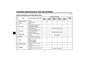
Replacing the air filter element The air filter element should be re-
placed at the intervals specified in the
periodic maintenance and lubrication
chart. Replace the air filter element
more frequently if you are riding in un-
usually wet or dusty areas.
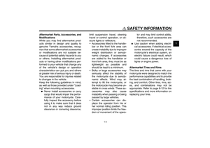
To replace the air filter element
1. Remove the air filter case cover by
removing the bolts.
2. Pull the air filter element out.3. Insert a new air filter element into
the air filter case. NOTICE: Make
sure that the air filter element is
properly seated in the air filter
case. The engine should never
be operated without the air filter
element installed, otherwise the
piston(s) and/or cylinder(s) may
become excessively worn.
[ECA10481]
4. Install the air filter case cover by in-
stalling the bolts.
1. Bolt
2. Air filter case cover12
1
1. Air filter element
1
U26PE1E0.book Page 11 Thursday, July 16, 2009 8:21 AM
Page 51 of 84
 at the
throttle grip. Periodicall")
PERIODIC MAINTENANCE AND ADJUSTMENT
6-12
6
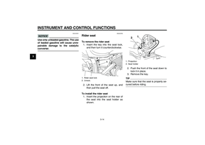
EAU21382
Checking the throttle cable
free play The throttle cable free play should mea-
sure 4.0–6.0 mm (0.16–0.24 in) at the
throttle grip. Periodically check the
throttle cable free play and, if neces-
sary, have a Yamaha dealer adjust it.
EAU21401
Valve clearance The valve clearance changes with use,
resulting in improper air-fuel mixture
and/or engine noise. To prevent this
from occurring, the valve clearance
must be adjusted by a Yamaha dealer
at the intervals specified in the periodic
maintenance and lubrication chart.
EAU21562
Tires To maximize the performance, durabil-
ity, and safe operation of your motorcy-
cle, note the following points regarding
the specified tires.
Tire air pressure
The tire air pressure should be checked
and, if necessary, adjusted before each
ride.
WARNING
EWA10501
Operation of this vehicle with im-
proper tire pressure may cause se-
vere injury or death from loss of
control.�
The tire air pressure must be
checked and adjusted on cold
tires (i.e., when the temperature
of the tires equals the ambient
temperature).
�
The tire air pressure must be ad-
justed in accordance with the
riding speed and with the total
weight of rider, passenger, car-
go, and accessories approved
for this model.
1. Throttle cable free play
1
U26PE1E0.book Page 12 Thursday, July 16, 2009 8:21 AM
Page 52 of 84

PERIODIC MAINTENANCE AND ADJUSTMENT
6-13
6
WARNING
EWA10511
Never overload your vehicle. Opera-
tion of an overloaded vehicle could
cause an accident.
Tire inspection
The tires must be checked before each
ride. If the center tread depth reaches
the specified limit, if the tire has a nail or
glass fragments in it, or if the sidewall is
cracked, have a Yamaha dealer re-
place the tire immediately.TIPThe tire tread depth limits may differ
from country to country. Always comply
with the local regulations.
Tire information
This motorcycle is equipped with cast
wheels and tubeless tires.
WARNING
EWA10461
The front and rear tires should be of
the same make and design, other-
wise the handling characteristics of
the vehicle may be different, which
could lead to an accident.After extensive tests, only the tires list-
ed below have been approved for this
model by Yamaha Motor Co., Ltd.
Tire air pressure (measured on cold
tires):
0–90 kg (0–198 lb):
Front:
225 kPa (2.25 kgf/cm², 33 psi)
Rear:
250 kPa (2.50 kgf/cm², 36 psi)
90–210 kg (198–463 lb):
Front:
225 kPa (2.25 kgf/cm², 33 psi)
Rear:
250 kPa (2.50 kgf/cm², 36 psi)
Maximum load*:
210 kg (463 lb)
* Total weight of rider, passenger, car-
go and accessories
1. Tire sidewall
2. Tire tread depthMinimum tire tread depth (front and
rear):
1.6 mm (0.06 in)
Front tire:
Size:
130/70-18M/C 63H
Manufacturer/model:
BRIDGESTONE/EXEDRA G721
J
DUNLOP/D404F
Rear tire:
Size:
170/70B16M/C 75H
Manufacturer/model:
BRIDGESTONE/EXEDRA G722
J
DUNLOP/K555
U26PE1E0.book Page 13 Thursday, July 16, 2009 8:21 AM
Page 53 of 84

PERIODIC MAINTENANCE AND ADJUSTMENT
6-14
6
WARNING
EWA10470
�
Have a Yamaha dealer replace
excessively worn tires. Besides
being illegal, operating the vehi-
cle with excessively worn tires
decreases riding stability and
can lead to loss of control.
�
The replacement of all wheel
and brake related parts, includ-
ing the tires, should be left to a
Yamaha dealer, who has the
necessary professional knowl-
edge and experience.
EAU21960
Cast wheels To maximize the performance, durabil-
ity, and safe operation of your vehicle,
note the following points regarding the
specified wheels.�
The wheel rims should be checked
for cracks, bends or warpage be-
fore each ride. If any damage is
found, have a Yamaha dealer re-
place the wheel. Do not attempt
even the smallest repair to the
wheel. A deformed or cracked
wheel must be replaced.
�
The wheel should be balanced
whenever either the tire or wheel
has been changed or replaced. An
unbalanced wheel can result in
poor performance, adverse han-
dling characteristics, and a short-
ened tire life.
�
Ride at moderate speeds after
changing a tire since the tire sur-
face must first be “broken in” for it
to develop its optimal characteris-
tics.
EAU48372
Adjusting the clutch lever free
play The clutch lever free play should mea-
sure 5.0–10.0 mm (0.20–0.39 in) as
shown. Periodically check the clutch le-
ver free play and, if necessary, adjust it
as follows.
1. Slide the rubber cover back at the
clutch lever.
2. Loosen the locknut.
3. To increase the clutch lever free
play, turn the clutch lever free play
adjusting bolt in direction (a). To1. Rubber cover
2. Clutch lever free play adjusting bolt
3. Locknut
4. Clutch lever free play
21
3
4
(a)
(b)
U26PE1E0.book Page 14 Thursday, July 16, 2009 8:21 AM
Page 54 of 84
.
TIPIf the specified clutch lever free play
could be obtained as described above")
PERIODIC MAINTENANCE AND ADJUSTMENT
6-15
6decrease the clutch lever free play,
turn the adjusting bolt in direction
(b).
TIPIf the specified clutch lever free play
could be obtained as described above,
skip steps 4–7.4. Fully turn the adjusting bolt in di-
rection (a) to loosen the clutch ca-
ble.
5. Slide the rubber cover back further
down the clutch cable, and then
loosen the locknut.6. To increase the clutch lever free
play, turn the clutch lever free play
adjusting nut in direction (a). To
decrease the clutch lever free play,
turn the adjusting nut in direction
(b).
7. Tighten the locknut at the clutch
cable, and then slide the rubber
cover to its original position.
8. Tighten the locknut at the clutch le-
ver, and then slide the rubber cov-
er to its original position.
EAU22093
Adjusting the brake lever free
play The brake lever free play should mea-
sure 10.0–15.0 mm (0.39–0.59 in) as
shown. Periodically check the brake le-
ver free play and, if necessary, adjust it
as follows.
1. Loosen the locknut at the brake le-
ver.
2. To increase the brake lever free
play, turn the brake lever free play
adjusting screw in direction (a). To
decrease the brake lever free play,
turn the adjusting screw in direc-
tion (b).
1. Rubber cover
2. Locknut
3. Clutch lever free play adjusting nut
1
23(a)
(b)
1. Locknut
2. Brake lever free play adjusting screw
3. Brake lever free play
(a)
3
1
2
(b)
U26PE1E0.book Page 15 Thursday, July 16, 2009 8:21 AM
Page 55 of 84

PERIODIC MAINTENANCE AND ADJUSTMENT
6-16
6 3. Tighten the locknut.
WARNING
EWA10630
�
After adjusting the brake lever
free play, check the free play
and make sure that the brake is
working properly.
�
A soft or spongy feeling in the
brake lever can indicate the
presence of air in the hydraulic
system. If there is air in the hy-
draulic system, have a Yamaha
dealer bleed the system before
operating the motorcycle. Air in
the hydraulic system will dimin-
ish the braking performance,
which may result in loss of con-
trol and an accident.
EAU22273
Brake light switches The brake light, which is activated by
the brake pedal and brake lever, should
come on just before braking takes ef-
fect. If necessary, adjust the rear brake
light switch as follows, but the front
brake light switch should be adjusted
by a Yamaha dealer.
Turn the rear brake light switch adjust-
ing nut while holding the rear brake light
switch in place. To make the brake light
come on earlier, turn the adjusting nut
in direction (a). To make the brake light
come on later, turn the adjusting nut in
direction (b).
EAU22392
Checking the front and rear
brake pads The front and rear brake pads must be
checked for wear at the intervals spec-
ified in the periodic maintenance and
lubrication chart.
EAU22430
Front brake pads
Each front brake pad is provided with
wear indicator grooves, which allow
you to check the brake pad wear with-
out having to disassemble the brake.
To check the brake pad wear, check
the wear indicator grooves. If a brake
pad has worn to the point that the wear
1. Rear brake light switch
2. Rear brake light switch adjusting nut
1
2
(a)
(b)
1. Brake pad wear indicator groove11
U26PE1E0.book Page 16 Thursday, July 16, 2009 8:21 AM
Page 56 of 84

PERIODIC MAINTENANCE AND ADJUSTMENT
6-17
6indicator grooves have almost disap-
peared, have a Yamaha dealer replace
the brake pads as a set.
EAU22500
Rear brake pads
Check each rear brake pad for damage
and measure the lining thickness. If a
brake pad is damaged or if the lining
thickness is less than 0.8 mm (0.03 in),
have a Yamaha dealer replace the
brake pads as a set.
EAU22580
Checking the brake fluid level Front brake
Rear brake
Insufficient brake fluid may allow air to
enter the brake system, possibly caus-
ing it to become ineffective.Before riding, check that the brake fluid
is above the minimum level mark and
replenish if necessary. A low brake fluid
level may indicate worn brake pads
and/or brake system leakage. If the
brake fluid level is low, be sure to check
the brake pads for wear and the brake
system for leakage.
Observe these precautions:
�
When checking the fluid level,
make sure that the top of the brake
fluid reservoir is level.
�
Use only the recommended quality
brake fluid, otherwise the rubber
seals may deteriorate, causing
leakage and poor braking perfor-
mance.
�
Refill with the same type of brake
fluid. Mixing fluids may result in a
harmful chemical reaction and
lead to poor braking performance.
1. Lining thickness
1
1. Minimum level mark
1. Minimum level mark
1
1
Recommended brake fluid:
DOT 4
U26PE1E0.book Page 17 Thursday, July 16, 2009 8:21 AM