2010 YAMAHA XT660Z lock
[x] Cancel search: lockPage 28 of 100

INSTRUMENT AND CONTROL FUNCTIONS
4-12
1
2
3
4
5
6
7
8
9
10
To close the fuel tank cap
1. Push the fuel tank cap into posi-
tion with the key inserted in the
lock.
2. Turn the key counterclockwise to
the original position, remove it,
and then close the lock cover.
TIP
The fuel tank cap cannot be closed
unless the key is in the lock. In addi-
tion, the key cannot be removed if the
cap is not properly closed and locked.
EWA11091
WARNING0
Make sure that the fuel tank cap is
properly closed after filling fuel.
Leaking fuel is a fire hazard.
EAU13221
Fuel
Make sure there is sufficient gasoline
in the tank.
EWA10881
WARNING0
Gasoline and gasoline vapors are
extremely flammable. To avoid fires
and explosions and to reduce the
risk of injury when refueling, follow
these instructions.
1. Before refueling, turn off the en-
gine and be sure that no one is
sitting on the vehicle. Never refuel
while smoking, or while in the
vicinity of sparks, open flames, or
other sources of ignition such as
the pilot lights of water heaters
and clothes dryers.
2. Do not overfill the fuel tank. When
refueling, be sure to insert the
pump nozzle into the fuel tank
filler hole. Stop filling when the fu-
el reaches the bottom of the filler
tube. Because fuel expands when
it heats up, heat from the engine
or the sun can cause fuel to spill
out of the fuel tank.
1. Fuel tank filler tube
2. Fuel level
3. Wipe up any spilled fuel immedi-
ately. NOTICE:Immediately wipe
off spilled fuel with a clean, dry,
soft cloth, since fuel may deteri-
orate painted surfaces or plas-
tic parts.
4. Be sure to securely close the fuel
tank cap.
EWA15151
WARNING0
Gasoline is poisonous and can
cause injury or death. Handle gaso-
line with care. Never siphon gaso-
line by mouth. If you should swal-
low some gasoline or inhale a lot of
gasoline vapor, or get some gaso-
line in your eyes, see your doctor
immediately. If gasoline spills on
XT660Z 04-04 ING-AUS:MY03 01-03 ING 11-05-2009 9:54 Pagina 4-12
Page 29 of 100

1
2
3
4
5
6
7
8
9
10
INSTRUMENT AND CONTROL FUNCTIONS
4-13
your skin, wash with soap and wa-
ter. If gasoline spills on your cloth-
ing, change your clothes.
EAU13390EAU13412
Fuel tank breather hose
1. Fuel tank breather hose
2. Clamp
Before operating the motorcycle:
●Check the fuel tank breather hose
connection.
●Check the fuel tank breather hose
for cracks or damage, and replace
it if damaged.
●Make sure that the fuel tank
breather hose is not blocked, and
clean it if necessary.
ECA11400
NOTICE
Use only unleaded gasoline. The use
of leaded gasoline will cause severe
damage to internal engine parts,
such as the valves and piston rings,
as well as to the exhaust system.
Your Yamaha engine has been de-
signed to use premium unleaded
gasoline with a research octane num-
ber of 95 or higher. If knocking (or
pinging) occurs, use a gasoline of a
different brand. Use of unleaded fuel
will extend spark plug life and reduce
maintenance costs.
Recommended fuel:
PREMIUM UNLEADED
GASOLINE ONLY
Fuel tank capacity:
23.0 L (6.07 US gal) (5.05 Imp.gal)
Fuel reserve amount (when the fuel
level warning light comes on):
6.7 L (1.77 US gal) (1.47 Imp.gal)
EAU13433
Catalytic converter
This model is equipped with a catalyt-
ic converter in the exhaust system.
EWA10862
WARNING0
The exhaust system is hot after op-
eration. To prevent a fire hazard or
burns:
●Do not park the vehicle near
possible fire hazards such as
grass or other materials that
easily burn.
●Park the vehicle in a place
where pedestrians or children
are not likely to touch the hot
exhaust system.
●Make sure that the exhaust
system has cooled down be-
fore doing any maintenance
work.
●Do not allow the engine to idle
more than a few minutes. Long
idling can cause a build-up of
heat.
XT660Z 04-04 ING-AUS:MY03 01-03 ING 11-05-2009 9:54 Pagina 4-13
Page 30 of 100

INSTRUMENT AND CONTROL FUNCTIONS
4-14
1
2
3
4
5
6
7
8
9
10
To install the seat
1. Projections
2. Seat holders
1. Insert the projection on the front of
the seat into the seat holder as
shown.
2. Push the rear of the seat down to
lock it in place.
3. Remove the key.
TIP
Make sure that the seat is properly se-
cured before riding.
EAU32980
Seat
To remove the seat
1. Seat lock
2. Unlock
1. Insert the key into the seat lock, and
then turn it counterclockwise.
2. While holding the key in that posi-
tion, lift the rear of the seat up, and
then pull the seat off.
ECA10701
NOTICE
Use only unleaded gasoline. The
use of leaded gasoline will cause
unrepairable damage to the catalyt-
ic converter.
XT660Z 04-04 ING-AUS:MY03 01-03 ING 11-05-2009 9:54 Pagina 4-14
Page 62 of 100

PERIODIC MAINTENANCE AND ADJUSTMENT
7-20
1
2
3
4
5
6
7
8
9
10
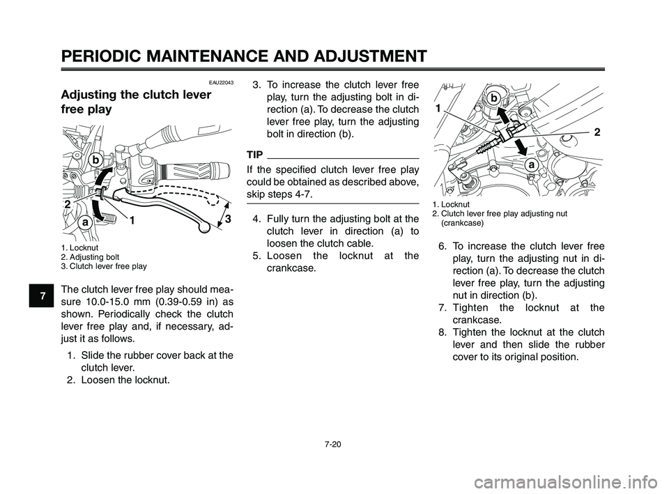
3. To increase the clutch lever free
play, turn the adjusting bolt in di-
rection (a). To decrease the clutch
lever free play, turn the adjusting
bolt in direction (b).
TIP
If the specified clutch lever free play
could be obtained as described above,
skip steps 4-7.
4. Fully turn the adjusting bolt at the
clutch lever in direction (a) to
loosen the clutch cable.
5. Loosen the locknut at the
crankcase.1. Locknut
2. Clutch lever free play adjusting nut
(crankcase)
6. To increase the clutch lever free
play, turn the adjusting nut in di-
rection (a). To decrease the clutch
lever free play, turn the adjusting
nut in direction (b).
7. Tighten the locknut at the
crankcase.
8. Tighten the locknut at the clutch
lever and then slide the rubber
cover to its original position.
1
b
a
2
EAU22043
Adjusting the clutch lever
free play
1. Locknut
2. Adjusting bolt
3. Clutch lever free play
The clutch lever free play should mea-
sure 10.0-15.0 mm (0.39-0.59 in) as
shown. Periodically check the clutch
lever free play and, if necessary, ad-
just it as follows.
1. Slide the rubber cover back at the
clutch lever.
2. Loosen the locknut.
31
2
b
a
XT660Z 05-07 ING-AUS:MY03 04-06 ING 11-05-2009 10:09 Pagina 7-20
Page 64 of 100

PERIODIC MAINTENANCE AND ADJUSTMENT
7-22
1
2
3
4
5
6
7
8
9
10
Insufficient brake fluid may allow air to
enter the brake system, possibly caus-
ing it to become ineffective.
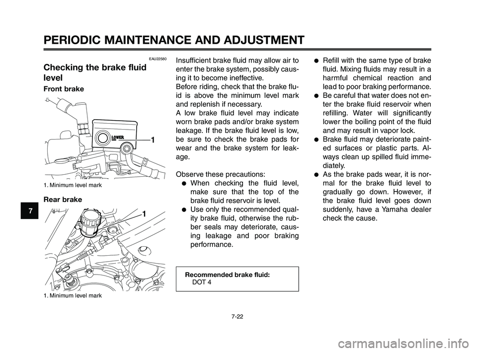
Before riding, check that the brake flu-
id is above the minimum level mark
and replenish if necessary.
A low brake fluid level may indicate
worn brake pads and/or brake system
leakage. If the brake fluid level is low,
be sure to check the brake pads for
wear and the brake system for leak-
age.
Observe these precautions:
●When checking the fluid level,
make sure that the top of the
brake fluid reservoir is level.
●Use only the recommended qual-
ity brake fluid, otherwise the rub-
ber seals may deteriorate, caus-
ing leakage and poor braking
performance.
●Refill with the same type of brake
fluid. Mixing fluids may result in a
harmful chemical reaction and
lead to poor braking performance.
●Be careful that water does not en-
ter the brake fluid reservoir when
refilling. Water will significantly
lower the boiling point of the fluid
and may result in vapor lock.
●Brake fluid may deteriorate paint-
ed surfaces or plastic parts. Al-
ways clean up spilled fluid imme-
diately.
●As the brake pads wear, it is nor-
mal for the brake fluid level to
gradually go down. However, if
the brake fluid level goes down
suddenly, have a Yamaha dealer
check the cause.
Recommended brake fluid:
DOT 4
EAU22580
Checking the brake fluid
level
Front brake
1. Minimum level mark
Rear brake
1. Minimum level mark
XT660Z 05-07 ING-AUS:MY03 04-06 ING 11-05-2009 10:10 Pagina 7-22
Page 66 of 100

PERIODIC MAINTENANCE AND ADJUSTMENT
7-24
1
2
3
4
5
6
7
8
9
10
1. Wheel axle
2. Drive chain slack adjusting bolt
3. Locknut
4. Alignment marks
TIP
Using the alignment marks on each
side of the swingarm, make sure that
both chain pullers are in the same po-
sition for proper wheel alignment.
3. Tighten the axle nut, then the lock-
nuts to their specified torques.
Tightening torques:
Axle nut:
105 Nm (10.5 m·kgf, 75 ft·lbf)
Locknut:
16 Nm (1.6 m·kgf, 11 ft·lbf)
EAU34314
To adjust the drive chain slack
1. Loosen the axle nut and the lock-
nut on each side of the swingarm.
2. To tighten the drive chain, turn the
drive chain slack adjusting bolt on
each side of the swingarm in di-
rection (a). To loosen the drive
chain, turn the adjusting bolt on
each side of the swingarm in di-
rection (b), and then push the rear
wheel forward. NOTICE: Improp-
er drive chain slack will over-
load the engine as well as other
vital parts of the motorcycle
and can lead to chain slippage
or breakage. To prevent this
from occurring, keep the drive
chain slack within the specified
limits.
XT660Z 05-07 ING-AUS:MY03 04-06 ING 11-05-2009 10:10 Pagina 7-24
Page 74 of 100

PERIODIC MAINTENANCE AND ADJUSTMENT
7-32
1
2
3
4
5
6
7
8
9
10
ECA10640
NOTICE
Do not use a fuse of a higher am-
perage rating than recommended
to avoid causing extensive damage
to the electrical system and possi-
bly a fire.
3. Turn the key to “ON” and turn on
the electrical circuit in question to
check if the device operates.
4. If the fuse immediately blows
again, have a Yamaha dealer
check the electrical system.
1. Parking lighting fuse
2. Signaling system fuse
3. Headlight fuse
4. Ignition fuse
5. Electronic fuel injection fuse
6. Radiator fan fuse
7. Backup fuse
8. Reserve fuses
The main fuse and fuse box are locat-
ed under the seat. (See page 7-31.)
If a fuse is blown, replace it as follows.
1. Turn the key to “OFF” and turn off
the electrical circuit in question.
2. Remove the blown fuse, and then
install a new fuse of the specified
amperage.
7
8
654321Specified fuses:
Main fuse:
30 A
Parking lighting fuse:
10 A
Signalling system fuse:
10 A
Headlight fuse:
20 A
Ignition fuse:
10 A
Fuel injection system fuse:
10 A
Radiator fan fuse:
7.5 A
Backup fuse (for odometer,
clock and immobilizer):
10 A
XT660Z 05-07 ING-AUS:MY03 04-06 ING 11-05-2009 10:10 Pagina 7-32
Page 76 of 100

PERIODIC MAINTENANCE AND ADJUSTMENT
7-34
1
2
3
4
5
6
7
8
9
10
ECA10650
NOTICE
Take care not to damage the fol-
lowing parts:
●Headlight bulb
Do not touch the glass part
of the headlight bulb to keep
it free from oil, otherwise the
transparency of the glass,
the luminosity of the bulb,
and the bulb life will be ad-
versely affected. Thoroughly
clean off any dirt and finger-
prints on the headlight bulb
using a cloth moistened with
alcohol or thinner.
●Headlight lens
Do not affix any type of tinted
film or stickers to the head-
light lens.
Do not use a headlight bulb
of a wattage higher than
specified.4. Connect the coupler, and then in-
stall the headlight bulb cover.
5. Have a Yamaha dealer adjust the
headlight beam if necessary.
EAU24204
Replacing a turn signal
light bulb
1. Screw
2. Turn signal light lens
3. Turn signal light bulb
1. Remove the turn signal light lens
by removing the screw.
2. Remove the burnt-out bulb by
pushing it in and turning it coun-
terclockwise.
3. Insert a new bulb into the socket,
push it in, and then turn it clock-
wise until it stops.
XT660Z 05-07 ING-AUS:MY03 04-06 ING 11-05-2009 10:10 Pagina 7-34