Page 39 of 96
INSTRUMENT AND CONTROL FUNCTIONS
3-23
2
34
5
6
7
8
9
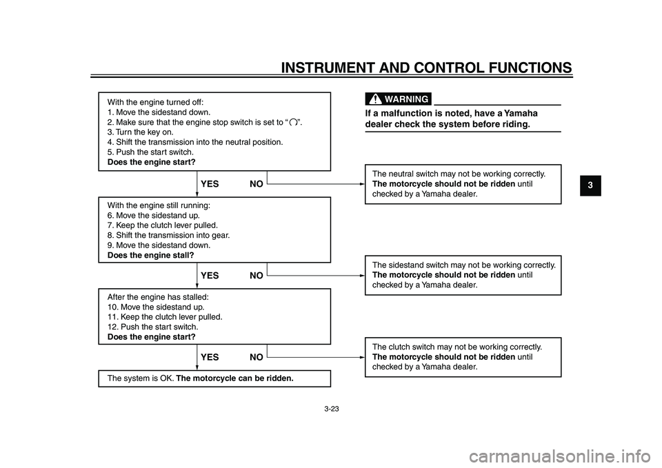
With the engine turned off:
1. Move the sidestand down.
2. Make sure that the engine stop switch is set to “
3. Turn the key on.
4. Shift the transmission into the neutral position.
5. Push the start switch.
Does the engine start?
With the engine still running:
6. Move the sidestand up.
7. Keep the clutch lever pulled.
8. Shift the transmission into gear.
9. Move the sidestand down.
Does the engine stall?
After the engine has stalled:
10. Move the sidestand up.
11. Keep the clutch lever pulled.
12. Push the start switch.
Does the engine start?
The system is OK. The motorcycle can be ridden.The neutral switch may not be working correctly.
The motorcycle should not be ridden until
checked by a Yamaha dealer.
The sidestand switch may not be working correctly.
The motorcycle should not be ridden until
checked by a Yamaha dealer.
The clutch switch may not be working correctly.
The motorcycle should not be ridden until
checked by a Yamaha dealer.
YES NO YES NO YES NO
If a malfunction is noted, have a Yamaha
dealer check the system before riding.
WARNING
”.
✼✥✯✣✲� ✥✦ �
���
�
����������������
Page 40 of 96
4-1
1
2
3
4
5
6
7
8
9
FOR YOUR SAFETY – PRE-OPERATION CHECKS
EAU15596
Inspect your vehicle each time you use it to make sure the vehicle is in safe operating condition. Always follow the inspection
and maintenance procedures and schedules described in the Owner’s Manual.
WARNING
EWA11151
Failure to inspect or maintain the vehicle properly increases the possibility of an accident or equipment damage.
Do not operate the vehicle if you find any problem. If a problem cannot be corrected by the procedures provided in
this manual, have the vehicle inspected by a Yamaha dealer.
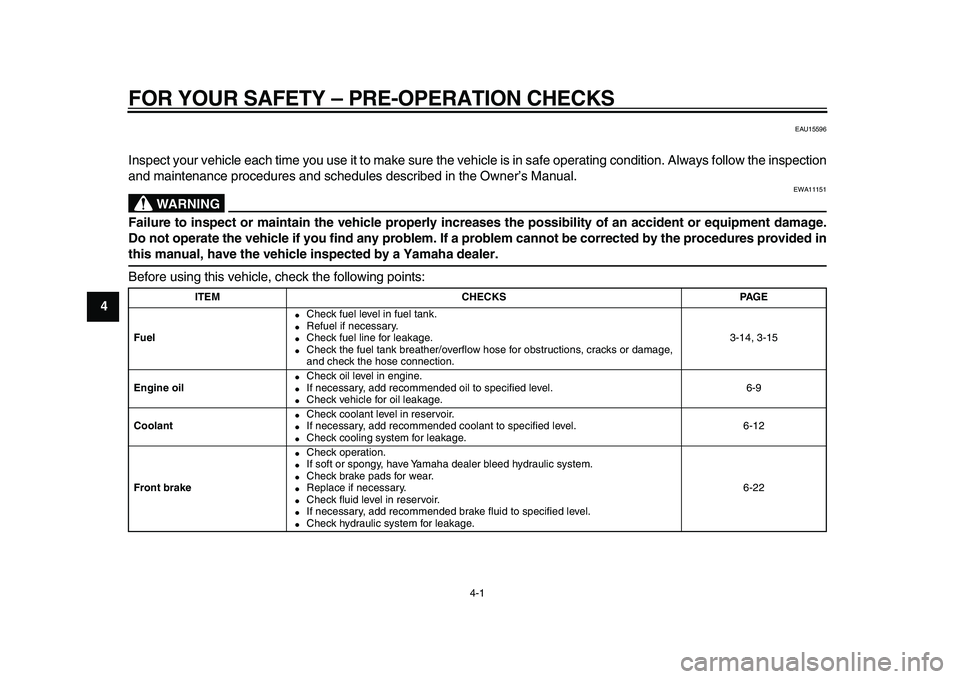
Before using this vehicle, check the following points:
ITEM CHECKS PAGE
Fuel
�
Check fuel level in fuel tank.
�
Refuel if necessary.
�
Check fuel line for leakage.
�
Check the fuel tank breather/overflow hose for obstructions, cracks or damage,
and check the hose connection.3-14, 3-15
Engine oil
�
Check oil level in engine.
�
If necessary, add recommended oil to specified level.
�
Check vehicle for oil leakage.6-9
Coolant
�
Check coolant level in reservoir.
�
If necessary, add recommended coolant to specified level.
�
Check cooling system for leakage.6-12
Front brake
�
Check operation.
�
If soft or spongy, have Yamaha dealer bleed hydraulic system.
�
Check brake pads for wear.
�
Replace if necessary.
�
Check fluid level in reservoir.
�
If necessary, add recommended brake fluid to specified level.
�
Check hydraulic system for leakage.6-22
✼✥✯✣✲� ✤ �
���
�
����������������
Page 43 of 96
5-1
2
3
4
56
7
8
9
OPERATION AND IMPORTANT RIDING POINTS
EAU15951
Read the Owner’s Manual carefully to
become familiar with all controls. If
there is a control or function you do not
understand, ask your Yamaha dealer.
WARNING
EWA10271
Failure to familiarize yourself with
the controls can lead to loss of con-
trol, which could cause an accident
or injury.
EAU48020
TIP
This model is equipped with a lean an-
gle sensor to stop the engine in case of
a turnover. In this case, the multi-func-
tion display indicates error code 30, but
this is not a malfunction. Turn the key to
“OFF” and then to “ON” to clear the er-
ror code. Failing to do so will prevent
the engine from starting even though
the engine will crank when pushing the
start switch.
EAU39894
Starting the engine
In order for the ignition circuit cut-off
system to enable starting, one of the
following conditions must be met:
�
The transmission is in the neutral
position.
�
The transmission is in gear with
the clutch lever pulled and the sid-
estand up.
See page 3-22 for more informa-
tion.
1. Turn the key to “ON” and make
sure that the engine stop switch is
set to “”.
The following warning lights and
indicator light should come on for a
few seconds, then go off.
�
Oil level warning light
�
Engine trouble warning light
�
Immobilizer system indicator light
�
ABS warning light
NOTICE
ECA11833
If a warning or indicator light does
not come on initially when the key is
turned to “ON”, or if a warning or in-
dicator light remains on, see page
3-4 for the corresponding warning
✼✥✯✣✲� ✤ �
���
�
����������������
Page 46 of 96
OPERATION AND IMPORTANT RIDING POINTS
5-4
1
2
3
4
5
6
7
8
9
EAU17213
Parking
When parking, stop the engine, and
then remove the key from the main
switch.
WARNING
EWA10311
�
Since the engine and exhaust
system can become very hot,
park in a place where pedestri-
ans or children are not likely to
touch them and be burned.
�
Do not park on a slope or on soft
ground, otherwise the vehicle
may overturn, increasing the
risk of a fuel leak and fire.
�
Do not park near grass or other
flammable materials which
might catch fire.
✼✥✯✣✲� ✧ �
���
�
����������������
Page 47 of 96
6-1
2
3
4
5
67
8
9
PERIODIC MAINTENANCE AND ADJUSTMENT
EAU17241
Periodic inspection, adjustment, and lu-
brication will keep your vehicle in the
safest and most efficient condition pos-
sible. Safety is an obligation of the vehi-
cle owner/operator. The most important
points of vehicle inspection, adjust-
ment, and lubrication are explained on
the following pages.
The intervals given in the periodic
maintenance and lubrication chart
should be simply considered as a gen-
eral guide under normal riding condi-
tions. However, depending on the
weather, terrain, geographical location,
and individual use, the maintenance in-
tervals may need to be shortened.
WARNING
EWA10321
Failure to properly maintain the ve-
hicle or performing maintenance ac-
tivities incorrectly may increase
your risk of injury or death during
service or while using the vehicle. If
you are not familiar with vehicle ser-
vice, have a Yamaha dealer perform
service.
WARNING
EWA15121
Turn off the engine when performing
maintenance unless otherwise
specified.
�
A running engine has moving
parts that can catch on body
parts or clothing and electrical
parts that can cause shocks or
fires.
�
Running the engine while ser-
vicing can lead to eye injury,
burns, fire, or carbon monoxide
poisoning – possibly leading to
death. See page 1-1 for more in-
formation about carbon monox-
ide.
EAU17521
Owner’s tool kit
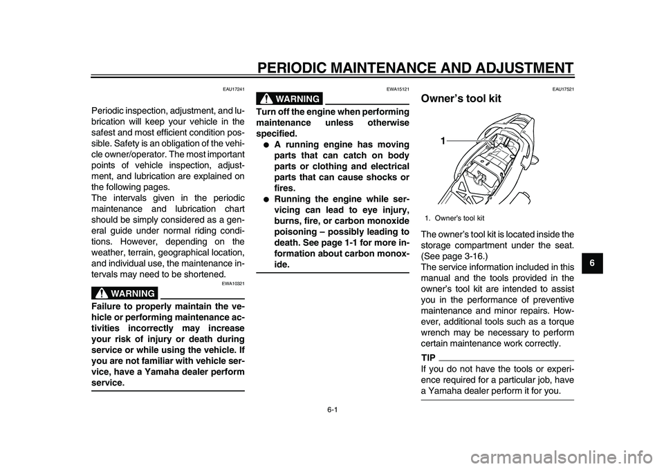
The owner’s tool kit is located inside the
storage compartment under the seat.
(See page 3-16.)
The service information included in this
manual and the tools provided in the
owner’s tool kit are intended to assist
you in the performance of preventive
maintenance and minor repairs. How-
ever, additional tools such as a torque
wrench may be necessary to perform
certain maintenance work correctly.
TIP
If you do not have the tools or experi-
ence required for a particular job, have
a Yamaha dealer perform it for you.
1. Owner’s tool kit
1
✼✥✯✣✲� ✤ �
���
�
����������������
Page 55 of 96
PERIODIC MAINTENANCE AND ADJUSTMENT
6-9
2
3
4
5
67
8
9
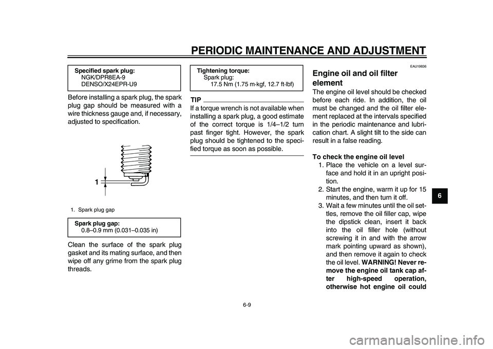
Before installing a spark plug, the spark
plug gap should be measured with a
wire thickness gauge and, if necessary,
adjusted to specification.
Clean the surface of the spark plug
gasket and its mating surface, and then
wipe off any grime from the spark plug
threads.
TIP
If a torque wrench is not available when
installing a spark plug, a good estimate
of the correct torque is 1/4–1/2 turn
past finger tight. However, the spark
plug should be tightened to the speci-
fied torque as soon as possible.
EAU19836
Engine oil and oil filter
element
The engine oil level should be checked
before each ride. In addition, the oil
must be changed and the oil filter ele-
ment replaced at the intervals specified
in the periodic maintenance and lubri-
cation chart. A slight tilt to the side can
result in a false reading.
To check the engine oil level
1. Place the vehicle on a level sur-
face and hold it in an upright posi-
tion.
2. Start the engine, warm it up for 15
minutes, and then turn it off.
3. Wait a few minutes until the oil set-
tles, remove the oil filler cap, wipe
the dipstick clean, insert it back
into the oil filler hole (without
screwing it in and with the arrow
mark pointing upward as shown),
and then remove it again to check
the oil level.
WARNING! Never re-
move the engine oil tank cap af-
ter high-speed operation,
otherwise hot engine oil could
Specified spark plug:
NGK/DPR8EA-9
DENSO/X24EPR-U9
1. Spark plug gap
Spark plug gap:
0.8–0.9 mm (0.031–0.035 in)
1
Tightening torque:
Spark plug:
17.5 Nm (1.75 m·kgf, 12.7 ft·lbf)
✼✥✯✣✲� ✬�
���
�
����������������
Page 59 of 96

PERIODIC MAINTENANCE AND ADJUSTMENT
6-13
2
3
4
5
67
8
9 For TDM900
For TDM900A
3. If the coolant is at or below the
minimum level mark, remove pan-
el B for TDM900 or panel A for
TDM900A (See page 6-7.), re-
move the reservoir cap, add cool-
ant to the maximum level mark,
and then install the reservoir cap
and the panel.
WARNING! Re-
move only the coolant reservoir
cap. Never attempt to remove
the radiator cap when the en-
gine is hot.
[EWA15161]
NOTICE:
If
coolant is not available, use dis-
tilled water or soft tap water in-
stead. Do not use hard water or
salt water since it is harmful to
the engine. If water has been
used instead of coolant, replace
it with coolant as soon as possi-
ble, otherwise the cooling sys-
tem will not be protected against
frost and corrosion. If water has
been added to the coolant, have
a Yamaha dealer check the anti-
freeze content of the coolant as
soon as possible, otherwise the
effectiveness of the coolant will
be reduced.
[ECA10472]
For TDM900
For TDM900A
1. Coolant reservoir
2. Maximum level mark
3. Minimum level mark
1. Maximum level mark
2. Coolant reservoir
3. Minimum level mark
1 2
33 1
2
1. Coolant reservoir cap
1. Coolant reservoir cap
Coolant reservoir capacity (up to the
maximum level mark):
0.25 L (0.26 US qt, 0.22 Imp.qt)
1
1
✼✥✯✣✲� ✤✦ �
���
�
����������������
Page 60 of 96

PERIODIC MAINTENANCE AND ADJUSTMENT
6-14
1
2
3
4
5
6
7
8
9
EAU27055
Replacing the air filter element
The air filter element should be re-
placed at the intervals specified in the
periodic maintenance and lubrication
chart. Replace the air filter element
more frequently if you are riding in un-
usually wet or dusty areas.
1. Remove the seat. (See
page 3-16.)
2. Remove cowlings A and B as well
as panels A and B. (See
page 6-7.)
3. Remove the fuel tank bolts.
TIP
For TDM900, skip steps 4 and 12.
4. Remove the rear brake fluid reser-
voir holder by removing the bolt.
For TDM900A
5. Lift the fuel tank away from the air
filter case, but do not disconnect
the fuel hoses.
WARNING! Make
sure that the fuel tank is well
supported. Do not tilt or pull the
fuel tank too much, otherwise
the fuel hoses may come loose,
which could cause fuel leakage
and a fire hazard.
[EWA10411]
6. Remove the air filter case cover by
removing the screws.
1. Bolt
1
1. Bolt1
1. Rear brake fluid reservoir
2. Rear brake fluid reservoir holder
3. Bolt
12
3
✼✥✯✣✲� ✤✧ �
���
�
����������������