Page 34 of 106
INSTRUMENT AND CONTROL FUNCTIONS
3-20
3
EAU13074
Fuel tank cap To open the fuel tank cap
Open the fuel tank cap lock cover, in-
sert the key into the lock, and then turn
it 1/4 turn clockwise. The lock will be re-
leased and the fuel tank cap can be
opened.
To close the fuel tank cap
1. Push the fuel tank cap into position
with the key inserted in the lock.
2. Turn the key counterclockwise to
the original position, remove it, and
then close the lock cover.
TIPThe fuel tank cap cannot be closed un-
less the key is in the lock. In addition,
the key cannot be removed if the cap is
not properly closed and locked.
WARNING
EWA11091
Make sure that the fuel tank cap is
properly closed after filling fuel.
Leaking fuel is a fire hazard.
1. Front wheel hub
1. Rear wheel hub
11
1. Fuel tank cap lock cover
2. Unlock.
U1DAE0E0.book Page 20 Friday, January 15, 2010 4:03 PM
Page 36 of 106

INSTRUMENT AND CONTROL FUNCTIONS
3-22
3or premium unleaded fuel. Use of un-
leaded fuel will extend spark plug life
and reduce maintenance costs.
EAU39451
Fuel tank breather/overflow
hose Before operating the motorcycle:�
Check the fuel tank breather/over-
flow hose connection.
�
Check the fuel tank breather/over-
flow hose for cracks or damage,
and replace it if damaged.
�
Make sure that the end of the fuel
tank breather/overflow hose is not
blocked, and clean it if necessary.
EAU13445
Catalytic converters This vehicle is equipped with catalytic
converters in the exhaust system.
WARNING
EWA10862
The exhaust system is hot after op-
eration. To prevent a fire hazard or
burns:�
Do not park the vehicle near
possible fire hazards such as
grass or other materials that
easily burn.
�
Park the vehicle in a place
where pedestrians or children
are not likely to touch the hot
exhaust system.
�
Make sure that the exhaust sys-
tem has cooled down before do-
ing any maintenance work.
�
Do not allow the engine to idle
more than a few minutes. Long
idling can cause a build-up of
heat.
1. Fuel tank breather/overflow hose
U1DAE0E0.book Page 22 Friday, January 15, 2010 4:03 PM
Page 37 of 106
INSTRUMENT AND CONTROL FUNCTIONS
3-23
3
NOTICE
ECA10701
Use only unleaded gasoline. The use
of leaded gasoline will cause unre-
pairable damage to the catalytic
converter.
EAU39492
Seats Passenger seat
To remove the passenger seat1. Insert the key into the passenger
seat lock, and then turn it counter-
clockwise.
2. Lift the front of the passenger seat
and pull it forward.To install the passenger seat
1. Insert the projections on the rear of
the passenger seat into the seat
holders as shown, and then push
the front of the seat down to lock it
in place.
2. Remove the key.
Rider seat
To remove the rider seat1. Remove the passenger seat.
2. Push the rider seat lock lever, lo-
cated under the back of the rider
seat, to the left as shown, and then
pull the seat off.
1. Passenger seat lock
2. Unlock.
1. Projection
2. Seat holder
U1DAE0E0.book Page 23 Friday, January 15, 2010 4:03 PM
Page 38 of 106
INSTRUMENT AND CONTROL FUNCTIONS
3-24
3
To install the rider seat
1. Insert the projection on the front of
the rider seat into the seat holder
as shown, and then push the rear
of the seat down to lock it in place.2. Install the passenger seat.
TIP�
Make sure that the seats are prop-
erly secured before riding.
�
The rider seat height can be ad-
justed to change the riding posi-
tion. (See page 3-24.)
EAU39632
Adjusting the rider seat height The rider seat height can be adjusted to
one of two positions to suit the rider’s
preference.
The rider seat height was adjusted to
the lower position at delivery.
To change the rider seat height to
the high position
1. Remove the rider seat. (See page
3-23.)
2. Remove the rider seat height posi-
tion adjuster by pulling it upward.
1. Rider seat lock lever
2. Rider seat
1. Projection
2. Seat holder
1. Low position
2. High position
U1DAE0E0.book Page 24 Friday, January 15, 2010 4:03 PM
Page 39 of 106

INSTRUMENT AND CONTROL FUNCTIONS
3-25
3
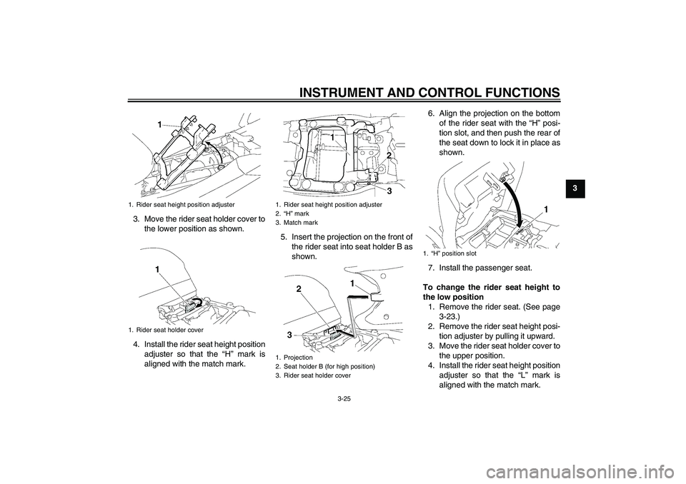
3. Move the rider seat holder cover to
the lower position as shown.
4. Install the rider seat height position
adjuster so that the “H” mark is
aligned with the match mark.5. Insert the projection on the front of
the rider seat into seat holder B as
shown.6. Align the projection on the bottom
of the rider seat with the “H” posi-
tion slot, and then push the rear of
the seat down to lock it in place as
shown.
7. Install the passenger seat.
To change the rider seat height to
the low position
1. Remove the rider seat. (See page
3-23.)
2. Remove the rider seat height posi-
tion adjuster by pulling it upward.
3. Move the rider seat holder cover to
the upper position.
4. Install the rider seat height position
adjuster so that the “L” mark is
aligned with the match mark.
1. Rider seat height position adjuster
1. Rider seat holder cover
1. Rider seat height position adjuster
2.“H” mark
3. Match mark
1. Projection
2. Seat holder B (for high position)
3. Rider seat holder cover
1.“H” position slot
U1DAE0E0.book Page 25 Friday, January 15, 2010 4:03 PM
Page 40 of 106

INSTRUMENT AND CONTROL FUNCTIONS
3-26
3
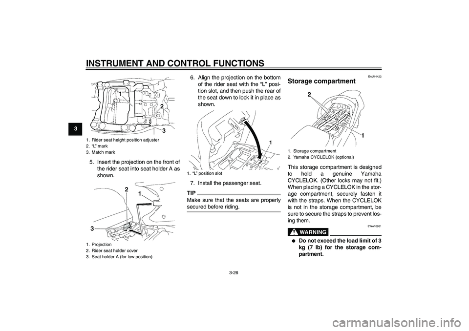
5. Insert the projection on the front of
the rider seat into seat holder A as
shown.6. Align the projection on the bottom
of the rider seat with the “L” posi-
tion slot, and then push the rear of
the seat down to lock it in place as
shown.
7. Install the passenger seat.
TIPMake sure that the seats are properly
secured before riding.
EAU14422
Storage compartment This storage compartment is designed
to hold a genuine Yamaha
CYCLELOK. (Other locks may not fit.)
When placing a CYCLELOK in the stor-
age compartment, securely fasten it
with the straps. When the CYCLELOK
is not in the storage compartment, be
sure to secure the straps to prevent los-
ing them.
WARNING
EWA10961
�
Do not exceed the load limit of 3
kg (7 lb) for the storage com-
partment.
1. Rider seat height position adjuster
2.“L” mark
3. Match mark
1. Projection
2. Rider seat holder cover
3. Seat holder A (for low position)
1
2
3
1.“L” position slot
1. Storage compartment
2. Yamaha CYCLELOK (optional)
U1DAE0E0.book Page 26 Friday, January 15, 2010 4:03 PM
Page 81 of 106

PERIODIC MAINTENANCE AND ADJUSTMENT
6-23
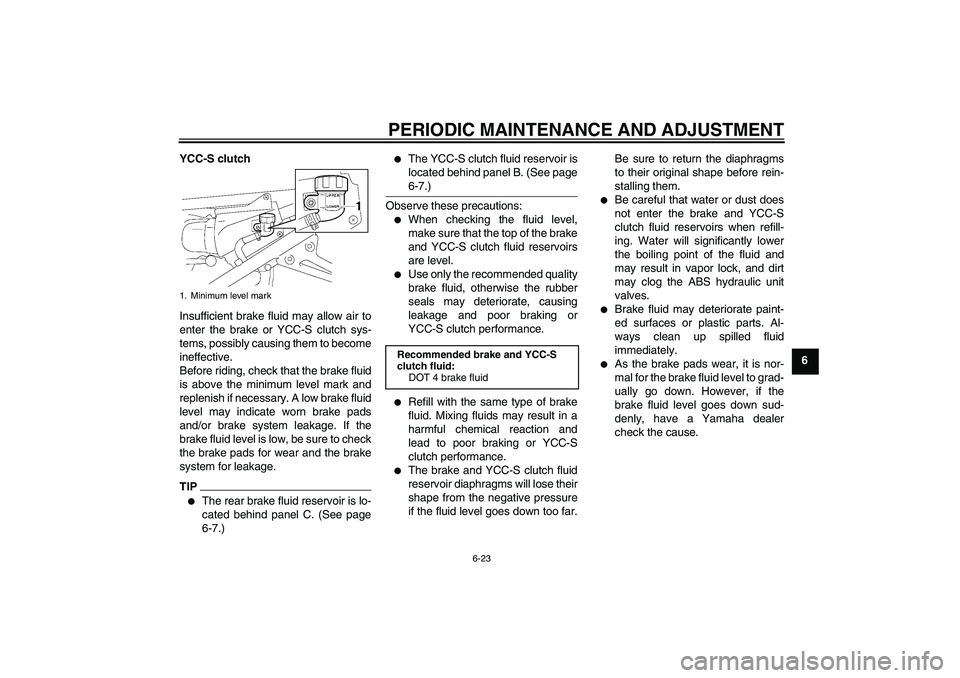
6 YCC-S clutch
Insufficient brake fluid may allow air to
enter the brake or YCC-S clutch sys-
tems, possibly causing them to become
ineffective.
Before riding, check that the brake fluid
is above the minimum level mark and
replenish if necessary. A low brake fluid
level may indicate worn brake pads
and/or brake system leakage. If the
brake fluid level is low, be sure to check
the brake pads for wear and the brake
system for leakage.
TIP�
The rear brake fluid reservoir is lo-
cated behind panel C. (See page
6-7.)
�
The YCC-S clutch fluid reservoir is
located behind panel B. (See page
6-7.)
Observe these precautions:�
When checking the fluid level,
make sure that the top of the brake
and YCC-S clutch fluid reservoirs
are level.
�
Use only the recommended quality
brake fluid, otherwise the rubber
seals may deteriorate, causing
leakage and poor braking or
YCC-S clutch performance.
�
Refill with the same type of brake
fluid. Mixing fluids may result in a
harmful chemical reaction and
lead to poor braking or YCC-S
clutch performance.
�
The brake and YCC-S clutch fluid
reservoir diaphragms will lose their
shape from the negative pressure
if the fluid level goes down too far.Be sure to return the diaphragms
to their original shape before rein-
stalling them.
�
Be careful that water or dust does
not enter the brake and YCC-S
clutch fluid reservoirs when refill-
ing. Water will significantly lower
the boiling point of the fluid and
may result in vapor lock, and dirt
may clog the ABS hydraulic unit
valves.
�
Brake fluid may deteriorate paint-
ed surfaces or plastic parts. Al-
ways clean up spilled fluid
immediately.
�
As the brake pads wear, it is nor-
mal for the brake fluid level to grad-
ually go down. However, if the
brake fluid level goes down sud-
denly, have a Yamaha dealer
check the cause.
1. Minimum level mark
Recommended brake and YCC-S
clutch fluid:
DOT 4 brake fluid
U1DAE0E0.book Page 23 Friday, January 15, 2010 4:03 PM
Page 88 of 106

PERIODIC MAINTENANCE AND ADJUSTMENT
6-30
6
EAU23659
Replacing the fuses The main fuse, the fuse boxes and the
ABS motor fuse are located under pan-
el A. (See page 6-7.)
If a fuse is blown, replace it as follows.
1. Turn the key to “OFF” and turn off
the electrical circuit in question.2. Remove the blown fuse, and then
install a new fuse of the specified
amperage. WARNING! Do not
use a fuse of a higher amperage
rating than recommended to
avoid causing extensive dam-
age to the electrical system and
possibly a fire.
[EWA15131]
1. Main fuse
2. Fuse box
3. ABS motor fuse
4. ABS motor spare fuse
1. Fuse box
2. Right radiator fan fuse
3. Left radiator fan fuse
4. Hazard fuse
5. Backup fuse (for clock and immobilizer sys-
tem)
6. ABS solenoid fuse
7. Fuel injection system fuse
8. Headlight fuse
9. Signaling system fuse
10.ABS control unit fuse
11.Ignition fuse
12.Auxiliary DC jack fuse
13.YCC-S motor control fuse
14.Spare fuse
20
0
2
714
8 9
10 11
12 13
U1DAE0E0.book Page 30 Friday, January 15, 2010 4:03 PM