Page 37 of 146
4-12
1
2
34
5
6
7
8
9
10
11
To install the seat
Insert the projection on the front of the seat into the
seat holder and push down on the seat at the rear.
Make sure that the seat is securely fitted.
EBU18992
Adjusting the front shock absorber
assemblies
The spring preload can be adjusted to suit the rid-
er’s weight and the riding conditions.
WARNING
EWB00400
Always adjust the shock absorber assemblies
on the left and right side to the same setting.
Uneven adjustment can cause poor handling
and loss of stability, which could lead to an ac-
1. Seat lock lever
1
1. Projection
2. Seat holder
1
2
✦✯��✬�✩✧�✤✲✣ ✤✥ ��
����������������������
Page 79 of 146

8-1
1
2
3
4
5
6
78
9
10
11
EBU28783
PERIODIC MAINTENANCE AND ADJUSTMENT
EBU21671
Periodic inspection, adjustment, and lubrication
will keep your vehicle in the safest and most effi-
cient condition possible. Safety is an obligation of
the vehicle owner/operator. The most important
points of vehicle inspection, adjustment, and lubri-
cation are explained on the following pages.
WARNING
EWB01841
Failure to properly maintain the vehicle or per-
forming maintenance activities incorrectly may
increase your risk of injury or death during ser-
vice or while using the vehicle. If you are not fa-
miliar with vehicle service, have a Yamaha
dealer perform the service.
WARNING
EWB02561
Turn off the engine when performing mainte-
nance unless otherwise specified.
�
A running engine has moving parts that can
catch on body parts or clothing and electri-
cal parts that can cause shocks or fires.
�
Running the engine while servicing can lead
to eye injury, burns, fire, or carbon monoxide
poisoning - possibly leading to death. See
page 2-1 for more information about carbon
monoxide.
The intervals given in the periodic maintenance
and lubrication chart should be considered as a
general guide under normal riding conditions.
However, DEPENDING ON THE WEATHER,
TERRAIN, GEOGRAPHICAL LOCATION, AND
INDIVIDUAL USE, THE MAINTENANCE INTER-
VALS MAY NEED TO BE SHORTENED.
EBU21691
Owner’s manual and tool kit
Be sure to put this owner’s manual and the low-
pressure tire gauge in the plastic bag and always
carry them along with the owner’s tool kit under the
seat.
✦✯��✬�✩✧�✤✲✣ ✤ ��
����������������������
Page 109 of 146

8-31
1
2
3
4
5
6
78
9
10
11
5. Move the throttle lever a few times and re-
check the position.
6. Install the fuel tank, side cover, radiator cover
and air filter case cover.
7. Connect the fuel hoses.
8. Install the seat.
EBU24020
Adjusting the engine idling speed
The engine idling speed must be checked and, if
necessary, adjusted as follows at the intervals
specified in the periodic maintenance and lubrica-tion chart.TIP
�
A diagnostic tachometer is needed to make this
adjustment.
�
The carburetor synchronization and the throttle
cable free play must be checked, and adjusted if
necessary, before adjusting the engine idling
speed.
1. Start the engine and warm it up.
TIP
The engine is warm when it quickly responds to the
throttle.
2. Attach the tachometer to the spark plug lead.
3. Turn in both pilot air screws until they lightly
seat.
4. Turn out both pilot air screws to specification.
(See the “Changing the carburetor settings”
section on the page 8-23.)
1. Adjusting nut
2. Locknut
1
2
✦✯��✬�✩✧�✤✲✣ ✦✤ ��
����������������������
Page 111 of 146

8-33
1
2
3
4
5
6
78
9
10
11
optimum engine performance.
TIP
If the specified idling speed cannot be obtained as
described above, have a Yamaha dealer make the
adjustment.
7. Install the seat.
EBU24045
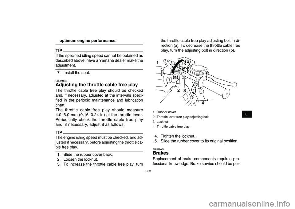
Adjusting the throttle cable free play
The throttle cable free play should be checked
and, if necessary, adjusted at the intervals speci-
fied in the periodic maintenance and lubrication
chart.
The throttle cable free play should measure
4.0–6.0 mm (0.16–0.24 in) at the throttle lever.
Periodically check the throttle cable free play
and, if necessary, adjust it as follows.
TIP
The engine idling speed must be checked, and ad-
justed if necessary, before adjusting the throttle ca-
ble free play.
1. Slide the rubber cover back.
2. Loosen the locknut.
3. To increase the throttle cable free play, turnthe throttle cable free play adjusting bolt in di-
rection (a). To decrease the throttle cable free
play, turn the adjusting bolt in direction (b).
4. Tighten the locknut.
5. Slide the rubber cover to its original position.
EBU29601
Brakes
Replacement of brake components requires pro-
fessional knowledge. Brake service should be per-
1. Rubber cover
2. Throttle lever free play adjusting bolt
3. Locknut
4. Throttle cable free play
2
3
4
(a)(b)
1
✦✯��✬�✩✧�✤✲✣ ✦✦ ��
����������������������
Page 127 of 146
8-49
1
2
3
4
5
6
78
9
10
11
6. Install the bulb holder cover.
NOTICE:
Make
sure the bulb holder cover is securely fit-
ted over the bulb holder and seated
against the reflector.
[ECB00681]
7. Place the headlight unit in the original posi-
tion, and then install the screw.
8. Adjust the headlight beam if necessary.
EBU25551
Adjusting a headlight beam NOTICE
ECB00690
It is advisable to have a Yamaha dealer make
this adjustment.
To raise a headlight beam, turn the headlight beam
1. Do not touch the glass part of the bulb.
1
1. Headlight bulb holder cover
2. Headlight bulb holder
3. Headlight unit
1
2
3
✦✯��✬�✩✧�✤✲✣ ✧✬ ��
����������������������