Page 4 of 592

TABLE OF CONTENTSIndex
4
Security and system setup ................................ 350
Using the phone book ........ 353
3-5. Using the interior lights Interior lights list ................. 361
• Personal/interior light main switch ............................... 362
• Personal/interior lights...... 362
• Luggage compartment light .................................. 363
3-6. Using the storage features List of storage features....... 364
• Glove box ......................... 365
• Console box ..................... 365
• Coin holder ....................... 369
• Cup holders ...................... 370
• Bottle holders ................... 374
• Auxiliary boxes ................. 375
• Trays ................................ 380
• Note pad holder ............... 381
3-7. Other interior features Sun visors .......................... 383
Vanity mirrors ..................... 384
Clock .................................. 385
Conversation mirror............ 386
Power outlets ..................... 387
Seat heaters ....................... 390
Armrests ............................. 392
Rear side sunshades ......... 393
Grocery bag hooks ............. 394
Coat hooks ......................... 396
Seatback tables.................. 397
Front seat side table........... 399
Floor mat ............................ 401
Luggage compartment features ............................ 402 Garage door opener ........... 405
Garage door opener box .... 410
Compass ............................ 413
4-1. Maintenance and care Cleaning and protecting the vehicle exterior ........... 418
Cleaning and protecting the vehicle interior ............ 421
4-2. Maintenance Maintenance requirements .................... 424
General maintenance ......... 426
Emission inspection and maintenance (I/M)
programs .......................... 429
4-3. Do-it-yourself maintenance Do-it-yourself service precautions ....................... 430
Hood ................................... 434
Positioning a floor jack........ 436
Engine compartment .......... 438
Tires.................................... 454
Tire inflation pressure ......... 463
Wheels................................ 467
Air conditioning filter ........... 469
Wireless remote control battery .............................. 472
Checking and replacing fuses ................................. 474
Light bulbs .......................... 486
4Maintenance and care
Page 176 of 592
176 2-2. Instrument cluster and information display
Instrument panel light controlThe brightness of the instrument panel lights can be adjusted.
Darker
Brighter
Optitron type meters only:
When the headlight switch is
turned on, the brightness will
be reduced slightly unless the
control button is turned fully
clockwise.
NOTICE
■To prevent damage to the engine and its components
●Do not let the indicator needle of the tachometer enter the red zone, which
indicates the maximum engine speed.
● The engine may be overheating if the engine coolant temperature gauge is
in the red zone (H). In this case, immediately stop the vehicle in a safe
place, and check the engine after it has cooled completely. (
P. 536)
Page 219 of 592
219
2
When driving
2-5. Driving information
Cargo and luggage
Adjusting the position of cross rails (if equipped)Turn the knobs counterclockwise
to release the cross rails.
Take notice of the following information about storage precau-
tions, cargo capacity and load.
●Stow cargo and luggage in the luggage compartment whenever
possible. Be sure all items are secured in place.
● Be careful to keep the vehicle level. Placing the weight as far for-
ward as possible helps maintain vehicle balance.
● For better fuel economy, do no t carry unnecessary weight.
■ Roof luggage carrier (if equipped)
Roof rails
Cross rails
STEP1
Page 220 of 592

220 2-5. Driving information
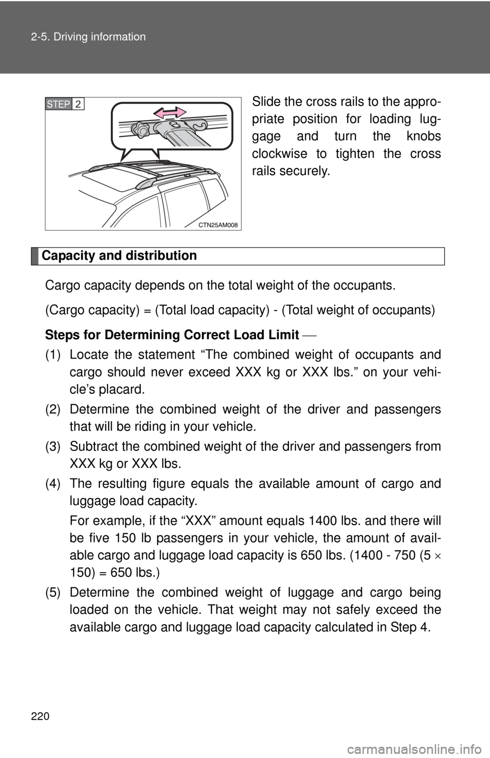
Slide the cross rails to the appro-
priate position for loading lug-
gage and turn the knobs
clockwise to tighten the cross
rails securely.
Capacity and distributionCargo capacity depends on the total weight of the occupants.
(Cargo capacity) = (Total load capacity) - (Total weight of occupants)
Steps for Determining Correct Load Limit
(1) Locate the statement “The co mbined weight of occupants and
cargo should never exceed XXX kg or XXX lbs.” on your vehi-
cle’s placard.
(2) Determine the combined weight of the driver and passengers that will be riding in your vehicle.
(3) Subtract the combined weight of the driver and passengers from XXX kg or XXX lbs.
(4) The resulting figure equals the available amount of cargo and luggage load capacity.
For example, if the “XXX” amount equals 1400 lbs. and there will
be five 150 lb passengers in your vehicle, the amount of avail-
able cargo and luggage load capacity is 650 lbs. (1400 - 750 (5
150) = 650 lbs.)
(5) Determine the combined wei ght of luggage and cargo being
loaded on the vehicle. That weig ht may not safely exceed the
available cargo and luggage load capacity calculated in Step 4.
STEP2
Page 239 of 592

Interior features3
239
3-5. Using the interior lightsInterior lights list ............... 361
• Personal/interior light main switch .................... 362
• Personal/interior lights ... 362
• Luggage compartment light ................................ 363
3-6. Using the storage features List of storage features .... 364
• Glove box....................... 365
• Console box ................... 365
• Coin holder .................... 369
• Cup holders ................... 370
• Bottle holders ................. 374
• Auxiliary boxes............... 375
• Trays .............................. 380
• Note pad holder ............. 381 3-7. Other interior features
Sun visors ........................ 383
Vanity mirrors ................... 384
Clock ................................ 385
Conversation mirror ......... 386
Power outlets ................... 387
Seat heaters..................... 390
Armrests........................... 392
Rear side sunshades ....... 393
Grocery bag hooks........... 394
Coat hooks ....................... 396
Seatback tables ............... 397
Front seat side table ........ 399
Floor mat .......................... 401
Luggage compartment features .......................... 402
Garage door opener......... 405
Garage door opener box ................................. 410
Compass .......................... 413
Page 240 of 592
240
3-1. Using the air conditioning system and defogger
Front manual air conditioning system (if equipped)
Adjusting the settings
■ Adjusting the temperature setting
Turn the temperature control dial clockwise (warm) or counter-
clockwise (cool).
If is not pressed, the system will blow ambient temperature air or
heated air.
For quick cooling, turn the temperature control dial to the “MAX A/C”
position. The air conditioning will automatically turn on and the air circu-
lation mode will be set to recirculated air mode.
When the dial is in the “MAX A/C” position, the air conditioning system
cannot be turned off even if is pressed.
Front air conditioning
fan speed control dial Air outlet selection dial
Air conditioning on/off switch
Temperature
control dialOutside air or recirculated air mode
Rear air conditioning
fan speed control dial
Page 241 of 592
241
3-1. Using the air conditioning system
and defogger
3
Interior features
■Adjusting the fan speed
Turn the fan speed control dial clockwise (increase) or counter-
clockwise (decrease).
Set the dial to “OFF” to turn the fan off.
■ Changing the air outlets
Set the air outlet selection di al to an appropriate position.
The positions between the air outlet selections shown below can also be
selected for more detailed adjustment.
Upper body
Upper body and feet
Feet
Page 243 of 592
243
3-1. Using the air conditioning system
and defogger
3
Interior features
Changing the rear setting
■ Adjusting the fan speed
Turn the rear fan speed control dial clockwise (increase) or counter-
clockwise (decrease).
When the rear fan speed control dial is turned to “REAR”, rear fan speed
can be operated from the rear air conditioning control panel. ( P. 253)
When the front or rear fan speed control dial is turned to “OFF”, the rear
air conditioning system is turned off.
Adjusting the position of and opening and closing the air outlets
Center outlets Direct air flow to the left or right,
up or down.
Right and left side outlets Direct air flow to the left or
right, up or down.
Turn the knob to open or close
the vent.