2010 SUZUKI SX4 light
[x] Cancel search: lightPage 226 of 297
7-21INSPECTION AND MAINTENANCE
80J23-03E
6) The handle of the CVT fluid dipstick is
colored red or orange for easy identifi-
cation.
Remove the dipstick, clean it and push
it back in until the cap seats. Pull out
the dipstick and read the fluid level.
The fluid level should be between the
two marks in the “HOT” range on the
dipstick.
7) Add just enough specified fluid through
the dipstick hole to fill the transaxle to
the proper level. It takes only 0.6 liters
(1.27 US pt) for CVT to raise the level
from “LOW” to “FULL”.Deterioration Checking or Chang-
ing OilSince special procedures, materials and
tools are required to check the deteriora-
tion of CVT oil or change, it is recom-
mended that you trust this job to your
authorized SUZUKI dealer.
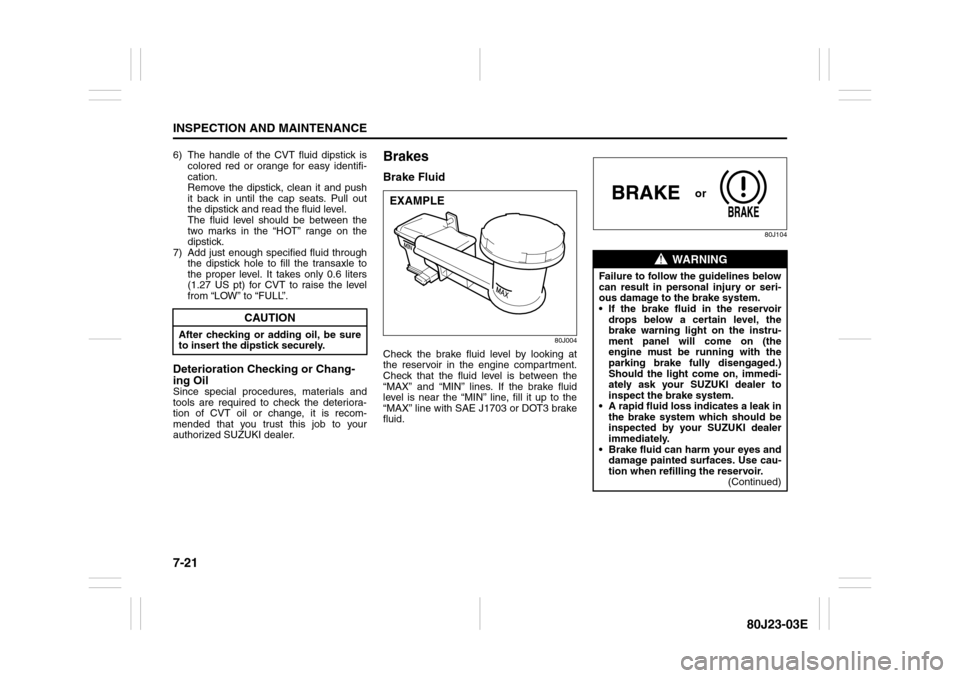
BrakesBrake Fluid
80J004
Check the brake fluid level by looking at
the reservoir in the engine compartment.
Check that the fluid level is between the
“MAX” and “MIN” lines. If the brake fluid
level is near the “MIN” line, fill it up to the
“MAX” line with SAE J1703 or DOT3 brake
fluid.
80J104
CAUTION
After checking or adding oil, be sure
to insert the dipstick securely.
EXAMPLE
WARNING
Failure to follow the guidelines below
can result in personal injury or seri-
ous damage to the brake system.
If the brake fluid in the reservoir
drops below a certain level, the
brake warning light on the instru-
ment panel will come on (the
engine must be running with the
parking brake fully disengaged.)
Should the light come on, immedi-
ately ask your SUZUKI dealer to
inspect the brake system.
A rapid fluid loss indicates a leak in
the brake system which should be
inspected by your SUZUKI dealer
immediately.
Brake fluid can harm your eyes and
damage painted surfaces. Use cau-
tion when refilling the reservoir.
(Continued)
or
Page 228 of 297
7-23INSPECTION AND MAINTENANCE
80J23-03E
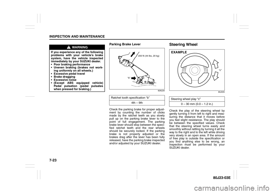
Parking Brake Lever
60A226
Check the parking brake for proper adjust-
ment by counting the number of clicks
made by the ratchet teeth as you slowly
pull up on the parking brake lever to the
point of full engagement. The parking
brake lever should stop between the speci-
fied ratchet teeth and the rear wheels
should be securely locked. If the parking
brake is not properly adjusted or the
brakes drag after the lever has been fully
released, have the parking brake inspected
and/or adjusted by your SUZUKI dealer.
Steering Wheel
80J005
Check the play of the steering wheel by
gently turning it from left to right and mea-
suring the distance that it moves before
you feel slight resistance. The play should
be between the specified values. Check
that the steering wheel turns easily and
smoothly without rattling by turning it all the
way to the right and to the left while driving
very slowly in an open area. If the amount
of free play is outside the specification or
you find anything else to be wrong, an
inspection must be performed by your
SUZUKI dealer.
WARNING
If you experience any of the following
problems with your vehicle’s brake
system, have the vehicle inspected
immediately by your SUZUKI dealer.
Poor braking performance
Uneven braking (brakes not work-
ing uniformly on all wheels.)
Excessive pedal travel
Brake dragging
Excessive noise
(Except ABS equipped vehicle)
Pedal pulsation (pedal pulsates
when pressed for braking.)
Ratchet tooth specification “b”
4th – 9th
200 N (44 lbs, 20 kg)
“b”
Steering wheel play “c”
0 – 30 mm (0.0 – 1.2 in.)
“c”
EXAMPLE
Page 232 of 297
7-27INSPECTION AND MAINTENANCE
80J23-03E
NOTE:
The tire inflation pressure will change
due to changes in atmospheric pres-
sure, temperature or tire temperature
when driving. To reduce the chance that
the low tire pressure warning light will
come on due to normal changes in tem-
perature and atmospheric pressure, it is
important to check and adjust the tire
pressures when the tires are cold. Tires
that appear to be at the specified pres-
sure when checked after driving, when
the tires are warm, could have pressure
below the specification when the tires
cool down. Also, tires that are inflated to
the specified pressure in a warm
garage may have pressure below the
specification when the vehicle is driven
outside in very cold temperature. If you
adjust the tire pressure in a garage that
is warmer than the outside tempera-
ture, you should add 1 psi to the recom-
mended cold tire inflation pressure for
every 10°F difference between garage
temperature and outside temperature.Measuring Air Pressure
Use the following steps to achieve
proper tire inflation:
1) Identify the recommended tire pres-
sure on the vehicle’s Tire and Load-
ing Information Label or in the
owner’s manual.
2) Remove the valve cap from the tire
valve stem.
3) Using a reliable pressure gauge,
measure the tire inflation pressure
by pressing the tire gauge firmly
onto the valve to get a pressure
measurement. Remember that
inflation pressures should be
checked when the tires are “cold”,
meaning before they have been
driven one mile or after sitting for
three hours or more allowing the tire
to cool to ambient air temperature.
4) If the air pressure is too high, slowly
release the air by pressing on the
tire valve stem with the edge of the
tire gauge until you reach the cor-
rect pressure.
5) If the air pressure is too low, fill the
tire with air at a service station until
it reaches the recommended pres-
sure.
6) Make sure all tires have the same
air pressure (unless the owner’s
manual indicates otherwise).
WARNING
Air pressures should be
checked when the tires are cold
or you may get inaccurate read-
ings.
Check the inflation pressure
from time to time while inflating
the tire gradually, until the spec-
ified pressure is obtained.
Never underinflate or overin-
flate the tires.
Underinflation can cause
unusual handling characteristics
or can cause the rim to slip on
the tire bead, resulting in an acci-
dent or damage to the tire or rim.
Underinflation can also cause
tires to overheat, leading to tire
failure.
Overinflation can cause the tire
to burst, resulting in personal
injury.
Overinflation can also cause
unusual handling characteristics
which may result in an accident.
Page 236 of 297
7-31INSPECTION AND MAINTENANCE
80J23-03E
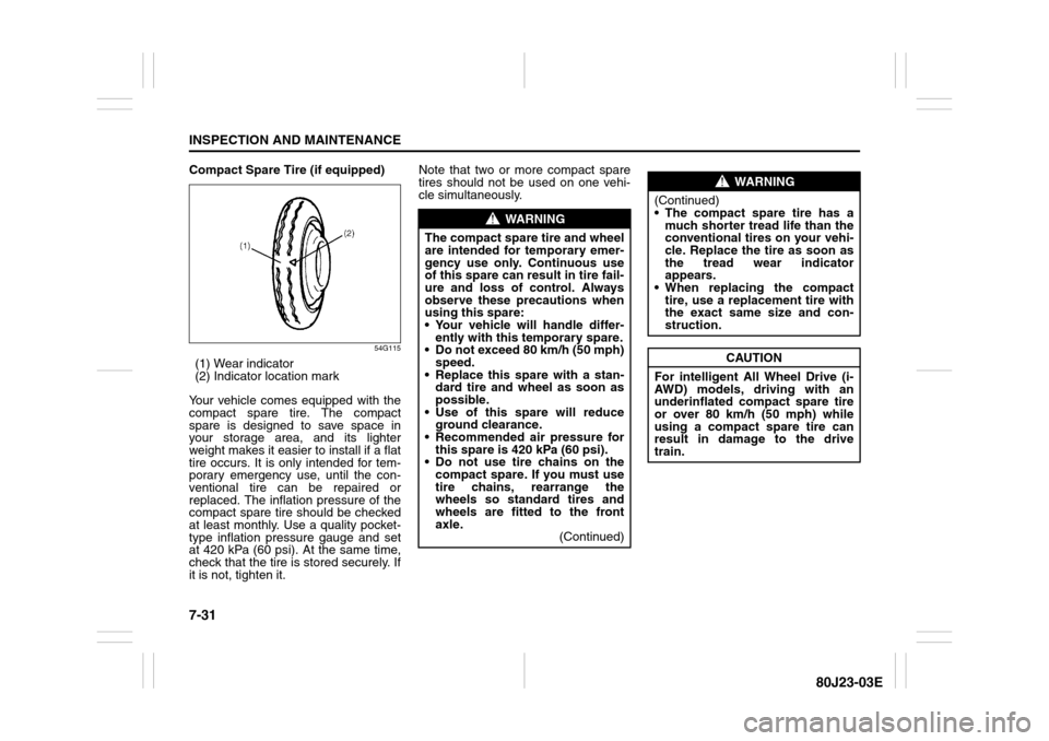
Compact Spare Tire (if equipped)
54G115
(1) Wear indicator
(2) Indicator location mark
Your vehicle comes equipped with the
compact spare tire. The compact
spare is designed to save space in
your storage area, and its lighter
weight makes it easier to install if a flat
tire occurs. It is only intended for tem-
porary emergency use, until the con-
ventional tire can be repaired or
replaced. The inflation pressure of the
compact spare tire should be checked
at least monthly. Use a quality pocket-
type inflation pressure gauge and set
at 420 kPa (60 psi). At the same time,
check that the tire is stored securely. If
it is not, tighten it.Note that two or more compact spare
tires should not be used on one vehi-
cle simultaneously.
WARNING
The compact spare tire and wheel
are intended for temporary emer-
gency use only. Continuous use
of this spare can result in tire fail-
ure and loss of control. Always
observe these precautions when
using this spare:
Your vehicle will handle differ-
ently with this temporary spare.
Do not exceed 80 km/h (50 mph)
speed.
Replace this spare with a stan-
dard tire and wheel as soon as
possible.
Use of this spare will reduce
ground clearance.
Recommended air pressure for
this spare is 420 kPa (60 psi).
Do not use tire chains on the
compact spare. If you must use
tire chains, rearrange the
wheels so standard tires and
wheels are fitted to the front
axle.
(Continued)
WARNING
(Continued)
The compact spare tire has a
much shorter tread life than the
conventional tires on your vehi-
cle. Replace the tire as soon as
the tread wear indicator
appears.
When replacing the compact
tire, use a replacement tire with
the exact same size and con-
struction.
CAUTION
For intelligent All Wheel Drive (i-
AWD) models, driving with an
underinflated compact spare tire
or over 80 km/h (50 mph) while
using a compact spare tire can
result in damage to the drive
train.
Page 242 of 297

7-37INSPECTION AND MAINTENANCE
80J23-03E
The main fuse, primary fuses and some of
the individual fuses are located in the
engine compartment. If the main fuse
blows, no electrical component will func-
tion. If a primary fuse blows, no electrical
component in the corresponding load
group will function. When replacing the
main fuse, a primary fuse or an individual
fuse, use a genuine SUZUKI replacement.
To remove a fuse, use the fuse puller pro-
vided in the fuse box. The amperage of
each fuse is shown in the back of the fuse
box cover.
60A243
NOTE:
Make sure that the fuse box always carries
spare fuses. MAIN FUSE / PRIMARY FUSE
(1) 80A All electric load
(2) 50APower window, Ignition,
Wiper, Starter
(3) 50ATail light, Rear defogger,
Door lock, Hazard/Horn,
Dome
(4) – Blank
(5) – Blank
(6) 15A Head light (Right) fuse
(7) 15A Head light (Left) fuse
(8) 20A Front fog light fuse
(9) – Blank
(10) 40A ABS motor fuse
(11) 30A Radiator fan fuse
(12) 30A ABS solenoid fuse
(13) 30A Starting motor fuse
(14) 50A Ignition switch fuse
(15) 30A Blower fan fuse
(16) 20A Air compressor fuse
(17) 15A Throttle motor fuse
(18) 15A Automatic transaxle fuse
(19) 15A Fuel injection fuse
(20) – Automatic transaxle relay
(21) – Air compressor relay
(22) – Fuel pump relay
(23) – Condenser fan relay
(24) – Front fog light relay
(25) – Throttle motor relay
(26) – FI MAIN relay
(27) – Starting motor relay
(28) – Radiator fan relay
(29) – Radiator fan relay 2
(30) – Radiator fan relay 3
WARNING
If the main fuse or a primary fuse
blows, be sure to have your vehicle
inspected by an authorized SUZUKI
dealer. Always use a genuine SUZUKI
replacement. Never use a substitute
such as a wire even for a temporary
fix, or extensive electrical damage
and a fire can result.
BLOWNOK
Page 243 of 297
7-38
INSPECTION AND MAINTENANCE
80J23-03E
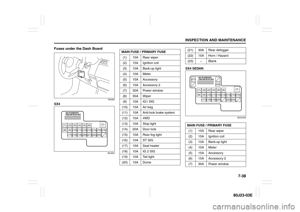
Fuses under the Dash Board
79J093
SX4
80J053
SX4 SEDAN
80JC003
(1) (2) (3) (4) (5) (6)
(8) (9) (10) (11) (12) (13) (14) (15) (16)
(18) (17) (19) (20) (21) (22) (23)(7)
MAIN FUSE / PRIMARY FUSE
(1) 15A Rear wiper
(2) 15A Ignition coil
(3) 10A Back-up light
(4) 10A Meter
(5) 15A Accessory
(6) 15A Accessory 2
(7) 30A Power window
(8) 30A Wiper
(9) 10A IG1 SIG
(10) 15A Air bag
(11) 10A Anti-lock brake system
(12) 15A 4WD
(13) 10A Stop light
(14) 20A Door lock
(15) 10A Rear fog light
(16) 10A ST SIG
(17) 15A Seat heater
(18) 10A IG 2 SIG
(19) 10A Tail light
(20) 15A Dome
(21) 30A Rear defogger
(22) 15A Horn / Hazard
(23) – Blank
MAIN FUSE / PRIMARY FUSE
(1) 15A Rear wiper
(2) 15A Ignition coil
(3) 10A Back-up light
(4) 10A Meter
(5) 15A Accessory
(6) 15A Accessory 2
(7) 30A Power window
(1) (2) (3) (4) (5) (6)
(8) (9) (10) (11) (12) (13)
(21)
(24)
(14) (15) (16)
(18) (17) (19) (20) (22) (23)(7)
Page 244 of 297

7-39INSPECTION AND MAINTENANCE
80J23-03E
The fuses are also located under the
driver’s side of the dashboard. Remove the
fuse box cover by pulling it off. The amper-
age of each fuse is shown on the top of the
fuse box cover.
65D046
Headlight AimingSince special procedures are required, we
recommend you take your vehicle to your
SUZUKI dealer for headlight alignment. (8) 30A Wiper
(9) 10A IG1 SIG
(10) 15A Air bag
(11) 10A Anti-lock brake system
(12) – Blank
(13) 10A Stop light
(14) 20A Door lock
(15) 10A Rear fog light
(16) 10A ST SIG
(17) 15A Seat heater
(18) 10A IG 2 SIG
(19) 10A Tail light
(20) 15A Dome
(21) 30A Rear defogger
(22) 15A Horn / Hazard
(23) – Blank
(24) 30A Rear defogger
WARNING
Always be sure to replace a blown
fuse with a fuse of the correct amper-
age. Never use a substitute such as
aluminum foil or wire to replace a
blown fuse. If you replace a fuse and
the new one blows in a short period
of time, you may have a major electri-
cal problem. Have your vehicle
inspected immediately by your
SUZUKI dealer.
BLOWN OK
Page 245 of 297
7-40
INSPECTION AND MAINTENANCE
80J23-03E
Bulb ReplacementNOTE:
If it is difficult to replace headlight bulbs or
position light bulbs due to under-hood
components trust this job to your dealer.
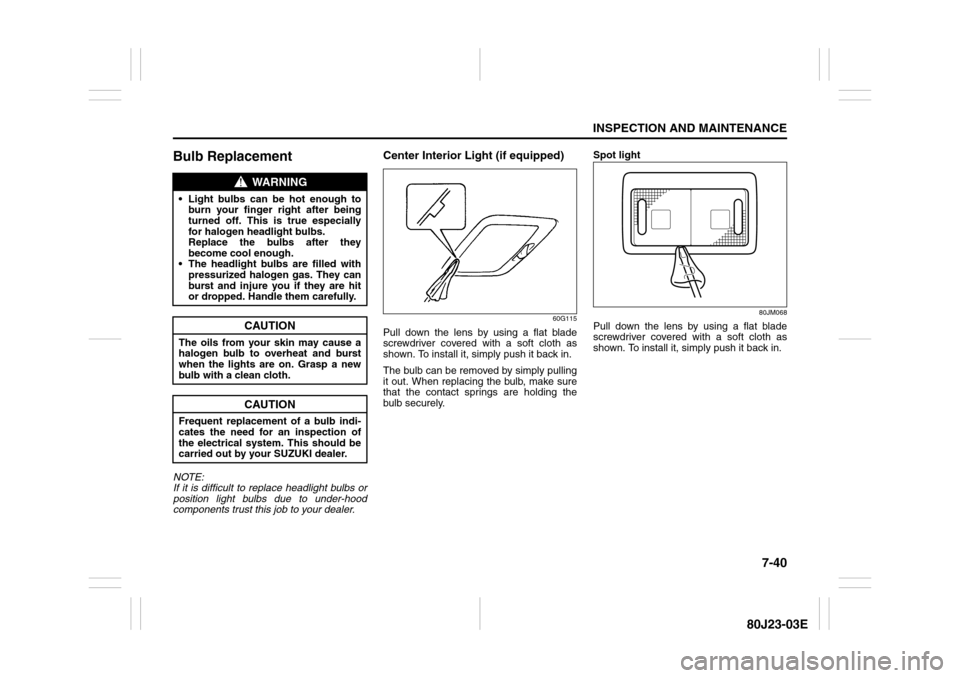
Center Interior Light (if equipped)
60G115
Pull down the lens by using a flat blade
screwdriver covered with a soft cloth as
shown. To install it, simply push it back in.
The bulb can be removed by simply pulling
it out. When replacing the bulb, make sure
that the contact springs are holding the
bulb securely.Spot light
80JM068
Pull down the lens by using a flat blade
screwdriver covered with a soft cloth as
shown. To install it, simply push it back in.
WARNING
Light bulbs can be hot enough to
burn your finger right after being
turned off. This is true especially
for halogen headlight bulbs.
Replace the bulbs after they
become cool enough.
The headlight bulbs are filled with
pressurized halogen gas. They can
burst and injure you if they are hit
or dropped. Handle them carefully.
CAUTION
The oils from your skin may cause a
halogen bulb to overheat and burst
when the lights are on. Grasp a new
bulb with a clean cloth.
CAUTION
Frequent replacement of a bulb indi-
cates the need for an inspection of
the electrical system. This should be
carried out by your SUZUKI dealer.