2010 SUBARU LEGACY emergency
[x] Cancel search: emergencyPage 324 of 448
9-14In case of emergency
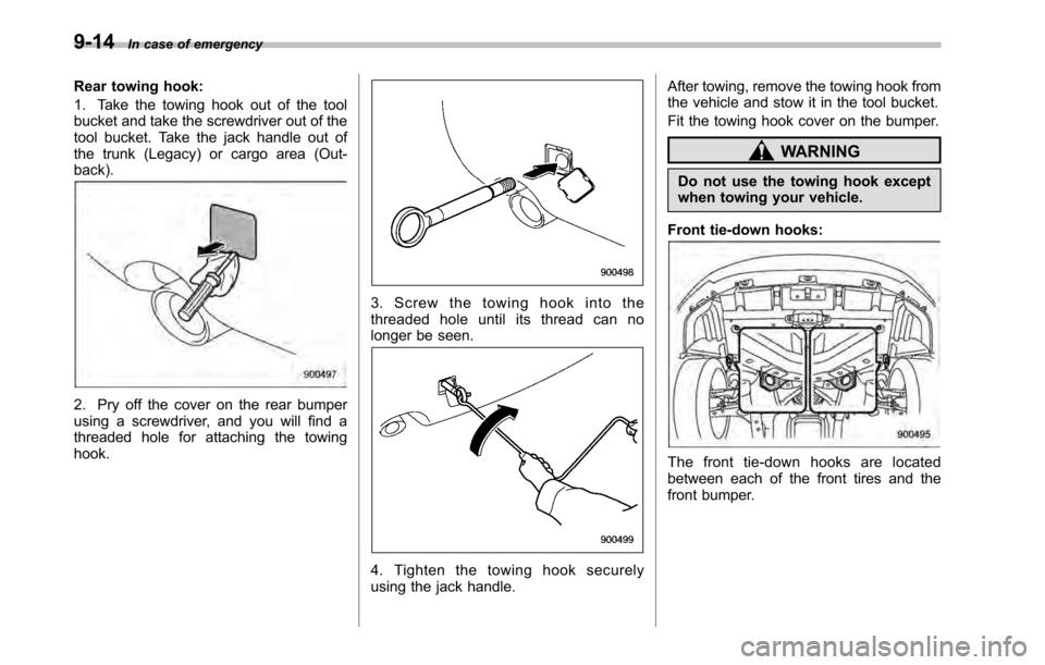
Rear towing hook:
1. Take the towing hook out of the tool
bucket and take the screwdriver out of the
tool bucket. Take the jack handle out of
the trunk (Legacy) or cargo area (Out-back).
2. Pry off the cover on the rear bumper
using a screwdriver, and you will find a
threaded hole for attaching the towinghook.
3. Screw the towing hook into the
threaded hole until its thread can no
longer be seen.
4. Tighten the towing hook securely
using the jack handle. After towing, remove the towing hook from
the vehicle and stow it in the tool bucket.
Fit the towing hook cover on the bumper.
WARNING
Do not use the towing hook except
when towing your vehicle.
Front tie-down hooks:
The front tie-down hooks are located
between each of the front tires and the
front bumper.
Page 325 of 448
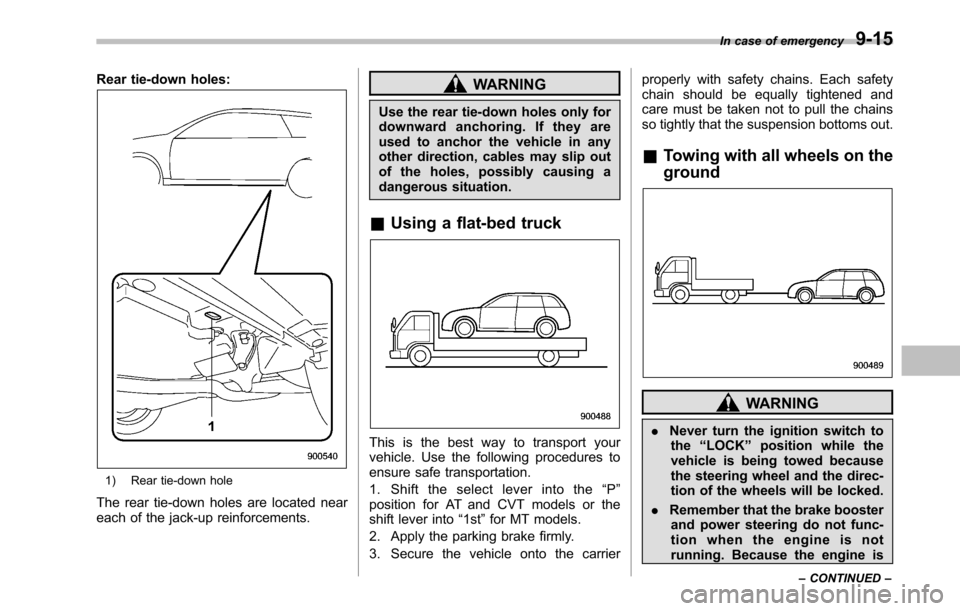
Rear tie-down holes:
1) Rear tie-down hole
The rear tie-down holes are located near
each of the jack-up reinforcements.
WARNING
Use the rear tie-down holes only for
downward anchoring. If they are
used to anchor the vehicle in any
other direction, cables may slip out
of the holes, possibly causing a
dangerous situation.
& Using a flat-bed truck
This is the best way to transport your
vehicle. Use the following procedures to
ensure safe transportation.
1. Shift the select lever into the “P ”
position for AT and CVT models or the
shift lever into “1st ”for MT models.
2. Apply the parking brake firmly.
3. Secure the vehicle onto the carrier properly with safety chains. Each safety
chain should be equally tightened and
care must be taken not to pull the chains
so tightly that the suspension bottoms out.
& Towing with all wheels on the ground
WARNING
. Never turn the ignition switch to
the “LOCK ”position while the
vehicle is being towed because
the steering wheel and the direc-
tion of the wheels will be locked.
. Remember that the brake booster
and power steering do not func-
tion when the engine is not
running. Because the engine is In case of emergency
9-15
– CONTINUED –
Page 326 of 448

9-16In case of emergency
turned off, it will take greater
effort to operate the brake pedal
and steering wheel.
CAUTION
. If transmission failure occurs,
transport your vehicle on a flat-
bed truck.
. Do not run the engine while being
towed using this method. Trans-
mission damage could result if
the vehicle is towed with the
engine running.
. For AT and CVT models, the
traveling speed must be limited
to less than 20 mph (30 km/h) and
the traveling distance to less
than 31 miles (50 km). For greater
speeds and distances, transport
your vehicle on a flat-bed truck.
1. Check the transmission and differen-
tial oil levels and add oil to bring it to the
upper level if necessary.
2. Release the parking brake and put the
transmission in neutral.
3. The ignition switch should be in the “ Acc ”position while the vehicle is being
towed.
4. Take up slack in the towline slowly to prevent damage to the vehicle.
Electronic parking brake–if
the electronic parking brake
cannot be releasedWARNING
. When the electronic parking
brake cannot be released, the
electronic parking brake system
may malfunction. Driving in such
conditions may cause an unex-
pected accident. Contact your
SUBARU dealer for inspection
as soon as possible.
. You can release the electronic
parking brake by using the elec-
tronic parking brake release tool
in case of an emergency. How-
ever, after releasing the electro-
nic parking brake by using the
electronic parking brake release
tool, contact your SUBARU deal-
er for inspection as soon aspossible.
. Release the electronic parking
brakebyusingtheelectronic
parking brake release tool on a
level road. Otherwise, the vehicle
may move, which could cause anaccident.
Page 327 of 448
.When releasing the electronic
parking brake by using the elec-
tronic parking brake release tool,
always perform the followingitems. – Shift the shift lever in the “1 ”
or “R ” position (MT models).
– Shift the select lever in the “P ”
position (AT and CVT models).
– Use tire stops under the tires.
. When releasing the electronic
parking brake by using the elec-
tronic parking brake release tool,
make sure that the ignition
switch is in the “LOCK ”position.
Otherwise, the electronic parking
brake system may operate and
the electronic parking brake re-
lease tool may rotate and unex-
pected accident may occur.
CAUTION
. Under certain weather conditions
(rain, snow, sandstorm, etc.), do
not release the electronic parking
brakebyusingtheelectronic
parking brake release tool. If
water or dust enters the device,
the device may malfunction. .
If the cap cannot be removed,
contact your SUBARU dealer for inspection.
. After releasing the electronic
parking brake by using the elec-
tronic parking brake release tool,
make sure that the cap is rein-
stalled to the parking brake re-
lease device. If the cap is not
reinstalled, water or dust enters
the device and the device maymalfunction.
NOTE
It may be difficult to release the elec-
tronic parking brake by using the
electronic parking brake release tool.
Have your SUBARU dealer release the
electronic parking brake if necessary.
In the event that you cannot release the
electronic parking brake by pulling the
electronic parking brake switch or by
depressing the accelerator pedal, you
can release the electronic parking brake
manually by using the electronic parking
brake release tool.
1. Shift the shift lever in the “1 ” or “R ”
position (MT models) or the select lever in the “P ”position (AT and CVT models).
2. Turn the ignition switch to the “LOCK ”
position. 3. Make sure that the brake system
warning light and the indicator light on
the parking brake switch have turned off.
4. Use tire stops under the tires to
prevent the vehicle from moving.
5. Take out the electronic parking brake
release tool. Refer to
“Maintenance tools ”
F 9-3. In case of emergency
9-17
– CONTINUED –
Page 328 of 448
9-18In case of emergency
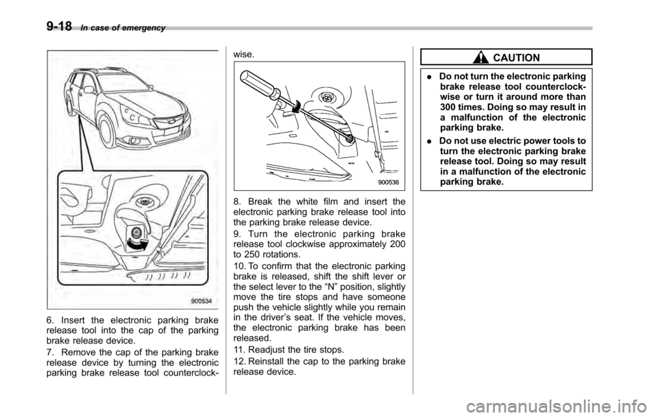
6. Insert the electronic parking brake
release tool into the cap of the parking
brake release device.
7. Remove the cap of the parking brake
release device by turning the electronic
parking brake release tool counterclock- wise.
8. Break the white film and insert the
electronic parking brake release tool into
the parking brake release device.
9. Turn the electronic parking brake
release tool clockwise approximately 200
to 250 rotations.
10. To confirm that the electronic parking
brake is released, shift the shift lever or
the select lever to the
“N ”position, slightly
move the tire stops and have someone
push the vehicle slightly while you remain
in the driver ’s seat. If the vehicle moves,
the electronic parking brake has beenreleased.
11. Readjust the tire stops.
12. Reinstall the cap to the parking brake
release device.
CAUTION
. Do not turn the electronic parking
brake release tool counterclock-
wise or turn it around more than
300 times. Doing so may result in
a malfunction of the electronic
parking brake.
. Do not use electric power tools to
turn the electronic parking brake
release tool. Doing so may result
in a malfunction of the electronic
parking brake.
Page 329 of 448
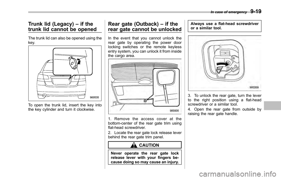
Trunk lid (Legacy)–if the
trunk lid cannot be opened
The trunk lid can also be opened using the
key.
To open the trunk lid, insert the key into
the key cylinder and turn it clockwise. Rear gate (Outback)
–if the
rear gate cannot be unlocked
In the event that you cannot unlock the
rear gate by operating the power door
locking switches or the remote keyless
entry system, you can unlock it from inside
the cargo area.
1. Remove the access cover at the
bottom-center of the rear gate trim using
flat-head screwdriver.
2. Locate the rear gate lock release lever
behind the rear gate trim panel.
CAUTION
Never operate the rear gate lock
release lever with your fingers be-
cause doing so may cause an injury. Always use a flat-head screwdriver
or a similar tool.
3. To unlock the rear gate, turn the lever
to the right position using a flat-head
screwdriver or a similar tool.
4. Open the rear gate from outside by
raising the rear gate handle.
In case of emergency
9-19
Page 330 of 448
9-20In case of emergency
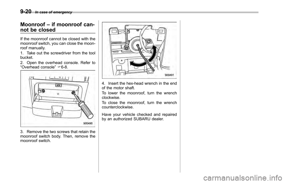
Moonroof –if moonroof can-
not be closed
If the moonroof cannot be closed with the
moonroof switch, you can close the moon-
roof manually.
1. Take out the screwdriver from the tool bucket.
2. Open the overhead console. Refer to “ Overhead console ”F 6-8.
3. Remove the two screws that retain the
moonroof switch body. Then, remove the
moonroof switch.
4. Insert the hex-head wrench in the end
of the motor shaft.
To lower the moonroof, turn the wrench clockwise.
To close the moonroof, turn the wrench counterclockwise.
Have your vehicle checked and repaired
by an authorized SUBARU dealer.
Page 430 of 448

14-2Index
A
ABS (Anti-lock Brake System) ..................................... 7-25
Warning light ................................................. 3-16, 7-25
Accessories ....................................................... 5-4, 11-50
Accessory power outlet ............................................... 6-10
Air cleaner element ................................................... 11-20
Air conditioner Automatic climate control system ............................. 4-12
Manual climate control system ................................... 4-7
Air filtration system ..................................................... 4-15
Air flow selection .......................................................... 4-2
Automatic climate control system ............................. 4-12
Manual climate control system ................................... 4-5
Alarm system ............................................................ 2-16
All-Wheel Drive warning light ....................................... 3-20
Aluminum wheel ....................................................... 11-42
Cleaning ............................................................... 10-3
Antenna system ........................................................... 5-2
Anti-lock Brake System (ABS) ..................................... 7-25
Arming the system ..................................................... 2-17
Armrest ..................................................................... 1-12
Ashtray ..................................................................... 6-12
AT OIL TEMP warning light ......................................... 3-15
Audio Antenna system ....................................................... 5-2
AUX unit operation ................................................. 5-28
CD player operation ............................................... 5-18
Control button ........................................................ 5-30
FM/AM radio operation ........................................... 5-10
Power and sound controls ......................................... 5-7
Satellite radio operations ......................................... 5-14 Set ........................................................................ 5-4XM
TMsatellite radio reception
................................... 5-2
Auto on/off headlights ................................................. 3-27
Sensor .................................................................. 3-28
Auto-dimming mirror/compass ...................................... 3-36
Automatic climate control system ................................... 4-8
Automatic transmission ............................................... 7-18
Capacities ............................................................. 12-4
Fluid ................................................................... 11-24
Manual mode ......................................................... 7-21
Oil temperature warning light (AT OIL TEMP) ............. 3-15
Select lever ........................................................... 7-19
Shift lock function ................................................... 7-20
Automatic/Emergency Locking Retractor (A/ELR) ........... 1-13
AUX unit operation ..................................................... 5-28
B Battery .................................................................... 11-47
Drainage prevention function ..................................... 2-6
Jump starting ......................................................... 9-10
Replacement (remote engine start transmitter) ........... 7-14
Replacement (remote keyless entry system) .............. 2-11
Booster seat .............................................................. 1-31
Bottle holder ............................................................... 6-9
Brake Assist .................................................................... 7-24
Booster ....................................................... 7-24, 11-32
Fluid ................................................................... 11-30
Pad and lining ...................................................... 11-34
Parking ................................................................. 7-34
Pedal .................................................................. 11-33