2010 SUBARU FORESTER reset
[x] Cancel search: resetPage 15 of 402

16 &Combination meter
! U.S.-spec. models
1) Tachometer (page 3-8)
2) Speedometer (page 3-6)
3) Fuel gauge (page 3-8)
4) Trip meter A/B selection and trip meter
reset knob (page 3-6)
5) Odometer/Trip meter (page 3-6)
6) Select lever and gear position indicator (AT models) (page 3-21)
7) Coolant temperature low indicator light/ Coolant temperature high warning light
(page 3-13)
Page 16 of 402

!Except U.S.-spec. models1) Tachometer (page 3-8)
2) Speedometer (page 3-6)
3) Fuel gauge (page 3-8)
4) Trip meter A/B selection and trip meter
reset knob (page 3-6)
5) Odometer/Trip meter (page 3-6)
6) Select lever and gear position indicator (AT models) (page 3-21)
7) Coolant temperature low indicator light/ Coolant temperature high warning light
(page 3-13) 17
– CONTINUED –
Page 127 of 402

3-16Instruments and controls
the tire to lose air rapidly. If you have
a flat tire, replace it with a spare tire
as soon as possible.
When a spare tire is mounted or a
wheel rim is replaced without the
original pressure sensor/transmitter
being transferred, the Low tire pres-
sure warning light will illuminate
steadily after blinking for approxi-
mately one minute. This indicates
the TPMS is unable to monitor all
four road wheels. Contact your
SUBARU dealer as soon as possible
for tire and sensor replacement and/
or system resetting. If the light
illuminates steadily after blinking
for approximately one minute,
promptly contact a SUBARU dealer
to have the system inspected.
CAUTION
The tire pressure monitoring system
is NOT a substitute for manually
checking tire pressure. The tire
pressure should be checked peri-
odically (at least monthly) using a
tire gauge. After any change to tire
pressure(s), the tire pressure mon-
itoring system will not re-check tire
inflation pressures until the vehicle
is first driven more than 20 mph (32 km/h). After adjusting the tire pres-
sures, increase the vehicle speed to
at least 20 mph (32 km/h) to start the
TPMS re-checking of the tire infla-
tion pressures. If the tire pressures
are now above the severe low
pressure threshold, the low tire
pressure warning light should turn
off a few minutes later. Therefore, be
sure to install the specified size for
the front and rear tires.
& ABS warning light
The ABS warning light illuminates when
the ignition switch is turned to the “ON ”
position and turns off after approximately 2seconds.
This is an indication that the ABS system
is working properly.
CAUTION
If the warning light behaves as
follows, the ABS system may not
work properly.
When the warning light is on, the
ABS function shuts down; however,
the conventional brake system con-
tinues to operate normally. . The warning light does not illu-
minate when the ignition switch is turned to the
“ON ”position.
. The warning light illuminates
when the ignition switch is
turned to the “ON ”position, but
it does not turn off even when the
vehicle speed exceeds approxi-
mately 8 mph (12 km/h).
. The warning light illuminates dur-
ing driving.
If any of these conditions occur,
have the ABS system repaired at
the first available opportunity by
your SUBARU dealer.
With a vehicle equipped with an EBD
system, the ABS warning light illuminates
together with the brake system warning
light if the EBD system becomes faulty.
For further details of the EBD system fault
warning, refer to “Brake system warning
light ”F 3-17.
NOTE
If the warning light behavior is as
described in the following, the ABS
system may be considered normal. . The warning light illuminates right
after the engine is started but turns off
immediately, remaining off.. The warning light remains on after
the engine has been started, but it
turns off when the vehicle speed
Page 135 of 402

3-24Instruments and controls
“ ON ”position, the indication does not
flash. NOTE
The outside temperature indication
may differ from the actual outside
temperature. The road surface freeze
warning indication should be treated
only as a guide. Be sure to check the
condition of the road surface beforedriving. & Average fuel consumption
1) U.S.-spec. models
2) Except U.S.-spec. models
This indication shows the average rate of
fuel consumption since the trip meter was
last reset. When either of the trip meter indications is
reset, the corresponding average fuel
consumption value is also reset.
NOTE . The indicated values vary in accor-
dance with changes in the vehicle ’s
running conditions. Also, the indicated
values may differ slightly from the
actual values and should thus be
treated only as a guide.. When either trip meter indication is
reset, the average fuel consumption
corresponding to that trip meter indica-
tion is not shown until the vehicle has
subsequently covered a distance of 1
mile (or 1 km). & To turn off fuel consumption
indicator display
The fuel consumption indicator display
can be turned off.
To turn off this display, turn the ignition
switch to the “LOCK ”position and press
the “+ ” button adjacent to the information
display for approximately 5 seconds.
Then, the information display and the
clock display will blink for 3 seconds to
notify you that the fuel consumption dis-
play has been turned off.
To restore the indicator, once again pressthe “+ ” button for approximately 5 sec- onds.
NOTE . The initial display setting of the fuel
consumption indicator of your vehicle
has been set to operational at the time
of shipment from the factory. . The average fuel consumption is
calculated even while the indicator is
not displayed.. Even if you turn off the fuel con-
sumption indicator, the fuel consump-
tion indicator will automatically turn on
when the battery voltage is discon-
nected and then reconnected for bat-
tery replacement or fuse replacement.
Page 140 of 402

Wiper and washer
WARNING
In freezing weather, do not use the
windshield washer until the wind-
shield is sufficiently warmed by the
defroster.
Otherwise the washer fluid can
freeze on the windshield, blocking
your view.
CAUTION
. Do not operate the washer con-
tinuously for more than 10 sec-
onds, or when the washer fluid
tank is empty. This may cause
overheating of the washer motor.
Check the washer fluid level
frequently, such as at fuel stops.
. Do not operate the wipers when
the windshield or rear window is
dry. This may scratch the glass,
damage the wiper blades and
cause the wiper motor to burn
out. Before operating the wiper
on a dry windshield or rear
window, always use the wind-
shield washer. .
In freezing weather, be sure that
the wiper blades are not frozen to
the windshield or rear window
before switching on the wipers.
Attempting to operate the wiper
with the blades frozen to the
window glass could cause not
only the wiper blades to be
damaged but also the wiper mo-
tor to burn out. If the wiper
blades are frozen to the window
glass, be sure to operate the
defroster, windshield wiper dei-
cer (if equipped) or rear window
defogger before turning on the
wiper.
. If the wipers stop during opera-
tion because of ice or some other
obstruction on the window, the
wiper motor could burn out even
if the wiper switch is turned off. If
this occurs, promptly stop the
vehicle in a safe place, turn the
ignition switch to the “LOCK ”
position and clean the window
glass to allow proper wiper op-eration.
. Use clean water if windshield
washer fluid is unavailable. In
areas where water freezes in
winter, use SUBARU Windshield
Washer Fluid or the equivalent. Refer to
“Windshield washer
fluid ”F 11-38.
Also, when driving the vehicle
when there are freezing tempera-
tures, use non-freezing type wi-
per blades.
. Do not clean the wiper blades
with gasoline or a solvent, such
as paint thinner or benzine. This
will cause deterioration of the
wiper blades.
NOTE . The wiper operates only when the
ignition switch is in the “ON ”or “Acc ”
position. . The front wiper motor is protected
against overloads by a circuit breaker.
If the motor operates continuously
under an unusually heavy load, the
circuit breaker may trip to stop the
motor temporarily. If this happens, park
your vehicle in a safe place, turn off the
wiper switch, and wait for approxi-
mately 10 minutes. The circuit breaker
will reset itself, and the wipers will
again operate normally.. Clean your wiper blades and win-
dow glass periodically with a washer
solution to prevent streaking, and to
remove accumulations of road salt or Instruments and controls
3-29
– CONTINUED –
Page 144 of 402

button, the compass display is toggled on
or off. When the compass is on, an
illuminated compass reading will appear
in the upper right corner of the mirror.
Even with the mirror in anti-glare mode,
the mirror surface turns bright if the
transmission is shifted into reverse. This
is to ensure good rearward visibility duringreversing. !Photosensors
The mirror has a photosensor attached on
both the front and back sides. If the glare
from the headlights of vehicles behind you
strikes the mirror, these sensors detect it
and make the reflection surface of the
mirror dimmer to help prevent you from
being blinded. For this reason, use care
not to cover the sensors with stickers, or other similar items. Periodically wipe the
sensors clean using a piece of dry soft
cotton cloth or an applicator. !
Compass zone adjustment
Compass calibration zones
1. The zone setting is factory preset to
Zone 8. Refer to the “Compass calibration
zones ”map shown above to verify that the
compass zone setting is correct for your
geographical location.
2. Press and hold the right button for 3
seconds then release, and the word“ ZONE ”will briefly appear and then the
zone number will be displayed.
3. Press the right-hand button repeatedly
to cycle the display through all possible
zone settings. Stop cycling when the
correct zone setting for your location is displayed.
4. Releasing the button for 3 seconds will
exit the zone setting mode. !
Compass calibration
1. For optimum calibration, switch off all
nonessential electrical accessories (rear
window defogger, heater/air conditioning
system, spotlight, etc.) and ensure all
doors are shut.
2. Drive to an open, level area away from
large metallic objects or structures and
make certain the ignition switch is in the“ ON ”position.
3. Press and hold the right button for 6 - 7
seconds then release, and the compass
will enter the calibration mode. “CAL ”and
direction will be displayed.
4. Drive slowly in a circle until “CAL ”
disappears from the display (approxi-
mately two to three circles). The compass
is now calibrated.
5. Further calibration may be necessary
should outside influences cause the mirror
to read inaccurately. You will know that
this has occurred if your compass begins
to read in only limited directions. Should
you encounter this situation, return to step
one of the above procedure and recali-
brate the mirror. Instruments and controls
3-33
– CONTINUED –
Page 172 of 402

Antenna system.................................................. 5-2
Roof antenna ...................................................... 5-2
FM reception ....................................................... 5-2
XM
TMsatellite radio reception (if equipped) ...... 5-2
Installation of accessories .................................. 5-4
Audio set ............................................................. 5-4
Type A audio set (if equipped) ............................. 5-5
Type B audio set (if equipped) ............................. 5-6
Power and sound controls ................................. 5-7
Power switch and volume control ........................ 5-7
Sound control ..................................................... 5-7
Adjustable level of each mode ............................. 5-9
FM/AM radio operation ...................................... 5-10
FM/AM selection ................................................. 5-10
Tuning ............................................................... 5-10
Displaying radio PS (Program Service Name) and RT (Radio Text) ................................................ 5-12
Station preset .................................................... 5-12
Satellite radio operation (if equipped) .............. 5-13
XM
TMsatellite radio ............................................ 5-13
Sirius satellite radio ........................................... 5-13
Satellite radio reception ...................................... 5-13
Displaying satellite radio ID of tuner ................... 5-13Band selection
................................................... 5-14
Channel and category selection ......................... 5-14
Channel preset .................................................. 5-16
Display selection ............................................... 5-16
CD player operation .......................................... 5-17
How to insert a CD (type A) ................................ 5-17
How to insert a CD(s) (type B) .. .......................... 5-17
How to play back a CD ...................................... 5-19
To select a track from its beginning. ................... 5-19
Fast-forwarding and fast-reversing ..................... 5-20
Repeating .......................................................... 5-21
Random playback .............................................. 5-21
Scan ................................................................. 5-22
Display selection ............................................... 5-22
Folder selection ................................................. 5-23
How to eject a CD from the player (type A) .... ..... 5-23
How to eject CDs from the player (type B) ..... ..... 5-24
When the following messages are displayed. . ..... 5-25
Auxiliary input jack (if equipped). ..................... 5-25
Precautions to observe when handling a compact disc ................................................... 5-26
Audio control buttons (if equipped) ................. 5-28
MODE button ..................................................... 5-28 Audio
5
Page 183 of 402

5-12Audio
! Seek in PTY (Program type) group
In the PTY selection mode, when the
desired PTY group has been selected,
pressing the “SEEK ”button “
”or “”
seeks within that PTY group. Pressing “
”seeks up. Pressing “”
seeks down.
The control function returns to the normal
mode after approximately 10 seconds. &
Displaying radio PS (Pro-
gram Service Name) and RT
(Radio Text)
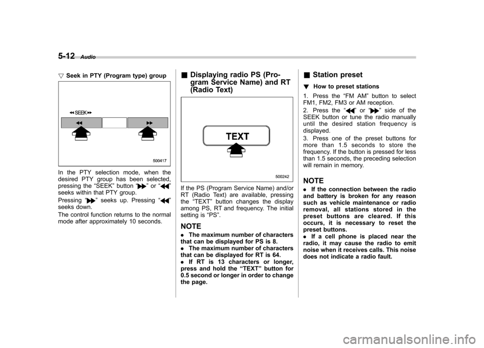
If the PS (Program Service Name) and/or
RT (Radio Text) are available, pressingthe “TEXT ”button changes the display
among PS, RT and frequency. The initial
setting is “PS ”.
NOTE . The maximum number of characters
that can be displayed for PS is 8. . The maximum number of characters
that can be displayed for RT is 64.. If RT is 13 characters or longer,
press and hold the “TEXT ”button for
0.5 second or longer in order to change
the page. &
Station preset
! How to preset stations
1. Press the “FM AM ”button to select
FM1, FM2, FM3 or AM reception.
2. Press the “
”or “”side of the
SEEK button or tune the radio manually
until the desired station frequency isdisplayed.
3. Press one of the preset buttons for
more than 1.5 seconds to store the
frequency. If the button is pressed for less
than 1.5 seconds, the preceding selection
will remain in memory. NOTE . If the connection between the radio
and battery is broken for any reason
such as vehicle maintenance or radio
removal, all stations stored in the
preset buttons are cleared. If this
occurs, it is necessary to reset the
preset buttons.. If a cell phone is placed near the
radio, it may cause the radio to emit
noise when it receives calls. This noise
does not indicate a radio fault.