2010 SUBARU FORESTER oil change
[x] Cancel search: oil changePage 43 of 402

1-20Seat, seatbelt and SRS airbags
You should hold the webbing end and
guide it back into the retractor while it is
rolling up. Neatly store the tongue plate in
the recessed compartment and then insert
the connector (tongue) plate into the slot.
CAUTION
. Do not allow the retractor to roll
up the seatbelt too quickly.
Otherwise, the metal tongue
plates may hit against the trim,
resulting in damaged trim. .
Have the seatbelt fully rolled up
so that the tongue plates are
neatly stored. A hanging tongue
plate can swing and hit against
the trim during driving, causing
damage to the trim.
& Seatbelt maintenance
To clean the seatbelts, use a mild soap
and lukewarm water. Never bleach or dye
the belts because this could seriously
affect their strength.
Inspect the seatbelts and attachments
including the webbing and all hardware
periodically for cracks, cuts, gashes,
tears, damage, loose bolts or worn areas.
Replace the seatbelts even if only minor
damage is found.CAUTION
. Keep the belts free of polishes,
oils, chemicals and particularly
battery acid.
. Never attempt to make modifica-
tions or changes that will prevent
the seatbelt from operating prop-
erly. Front seatbelt pretensioners
The driver
’s and front passenger ’s seat-
belts have a seatbelt pretensioner. The
seatbelt pretensioners for the driver ’s seat
and front passenger ’s seat operate at the
same time as the frontal, and side SRS
airbags. If the vehicle rolls over, they
operate simultaneously with the curtainairbag.
The front and side airbag sensors and the
rollover sensor are used as the preten-
sioner sensors. If a sensor detects a
certain predetermined amount of force
during a frontal collision, a side impact
collision or a rollover collision, the front
seatbelt is quickly drawn back in by the
retractor to take up the slack so that the
belt more effectively restrains the front
Page 112 of 402

Ignition switch..................................................... 3-3
LOCK .................................................................. 3-3
Acc..................................................................... 3-4
ON...................................................................... 3-4
START ................................................................ 3-4
Key reminder chime ............................................ 3-5
Ignition switch light ............................................. 3-5
Hazard warning flasher ....................................... 3-5
Meters and gauges. ............................................. 3-5
Combination meter illumination ........................... 3-5
Canceling the function for meter/gauge needle movement upon turning on the ignition switch ............................................................... 3-6
Speedometer ....................................................... 3-6
Odometer/Trip meter ............................................ 3-6
Tachometer ......................................................... 3-8
Fuel gauge .......................................................... 3-8
Warning and indicator lights .............................. 3-9
Seatbelt warning light and chime ........................ 3-10
SRS airbag system warning light ........................ 3-11
Front passenger ’s frontal airbag ON and OFF
indicators ......................................................... 3-12
CHECK ENGINE warning light/Malfunction indicator lamp .................................................. 3-12
Coolant temperature low indicator light/Coolant temperature high warning light ......................... 3-13
Charge warning light .......................................... 3-14
Oil pressure warning light .................................. 3-14
AT OIL TEMP warning light (AT models) ... ........... 3-14
Low tire pressure warning light (U.S.-spec. models) .......................................... 3-15 ABS warning light
.............................................. 3-16
Brake system warning light ................................ 3-17
Low fuel warning light ....................................... 3-18
Hill start assist warning light (MT models) ..... ..... 3-18
Door open warning light .................................... 3-18
All-Wheel Drive warning light (AT models) ..... ..... 3-18
Automatic headlight beam leveler warning light (models with HID headlights).. .......................... 3-18
Vehicle Dynamics Control operation indicator light ................................................................ 3-19
Vehicle Dynamics Control warning light/Vehicle Dynamics Control OFF indicator light ............... 3-19
Security indicator light ....................................... 3-20
SPORT mode indicator light (AT models) ............ 3-20
Select lever and gear position indicator (AT models) ..................................................... 3-21
Turn signal indicator lights ................................. 3-21
High beam indicator light ................................... 3-21
Cruise control indicator light .............................. 3-21
Cruise control set indicator light ........................ 3-21
Front fog light indicator light (if equipped) ..... ..... 3-21
Headlight indicator light ..................................... 3-21
Clock .................................................................. 3-22
Information display ............................................ 3-22
Outside temperature indicator .. .......................... 3-23
Average fuel consumption ................................. 3-24
To turn off fuel consumption indicator display ............................................................ 3-24
Light control switch ........................................... 3-25
Headlights ......................................................... 3-25
High/low beam change (dimmer) ........................ 3-26
Instruments and controls
3
Page 229 of 402

7-12Starting and operating
feature programming can be adjusted
using the following procedure.
1. Open the driver ’s door (the driver ’s
door must remain opened throughout the
entire process).
2. Insert the key into the vehicle ’s ignition
switch and turn to the “ON ”position.
3. Locate the small black programming
button behind the fuse box cover, on the
driver ’s side left under the dashboard
panel.
4. Press and hold the black programming
button for 10 to 15 seconds. The horn will
honk and the turn signal lights will flash
three times to indicate that the system has
entered programming mode. At this point
you can proceed to either step 5 or step 6.
5. To program a remote transmitter:
press and release the “
”button on each
transmitter. The horn will honk and the
turn signal lights will flash one time to
indicate a successful transmitter learn
each time the “
”button is pressed. You
can program up to eight transmitters.
6. To toggle the Horn Confirmation chirps
ON/OFF: press and release the brake to
toggle the feature. The horn will chirp and
the turn signal lights will flash one time to
indicate Confirmation Horn Chirps are“ OFF ”. The horn will honk and the turn
signal lights will flash 2 times to indicate
Confirmation Horn Chirps are “ON ”. Pressing the brake pedal repeatedly will
toggle the feature ON or OFF each time.
7. To exit the remote transmitter and
feature programming mode, turn the igni-
tion switch to the
“LOCK ”position, remove
the key from the ignition switch and test
operation of the remote transmitter(s) and
horn confirmation feature.
& System maintenance
! Changing the remote control bat-teries
CAUTION
. Do not let dust, oil or water get on
or in the remote engine start
transmitter when replacing the
battery.
. Be careful not to damage the
printed circuit board in the re-
mote engine start transmitter
when replacing the battery.
. Be careful not to allow children to
touch the battery and any re-
moved parts; children could
swallow them.
. There is a danger of explosion if
an incorrect replacement battery
is used. Replace only with the
same or equivalent type of bat- tery.
. Batteries should not be exposed
to excessive heat such as sun-
shine, fire or the like.
The two 3-volt lithium batteries (modelCR-1220 ) supplied in your remote control
should last approximately 3 years, de-
pending on usage. When the batteries
begin to weaken, you will notice a
decrease in range (distance from the
vehicle that your remote control operates).
Follow the instructions below to change
the remote control batteries.
Page 279 of 402
8-24Driving tips
nificant blind spot.
. Sufficient time should be taken to learn
the “feel ”of the vehicle/trailer combination
before starting out on a trip. In an area free
of traffic, practice turning, stopping and
backing up. ! Driving with a trailer
. You should allow for considerably more
stopping distance when towing a trailer.
Avoid sudden braking because it may
result in skidding or jackknifing and loss ofcontrol. . Avoid abrupt starts and sudden accel-
erations. If your vehicle has a manual
transmission, always start out in first gear
and release the clutch at moderate enginerevolution. . Avoid uneven steering, sharp turns and
rapid lane changes.. Slow down before turning. Make a
longer than normal turning radius because
the trailer wheels will be closer than the
vehicle wheels to the inside of the turn. In
a tight turn, the trailer could hit yourvehicle. . Crosswinds will adversely affect the
handling of your vehicle and trailer, caus-
ing sway. Crosswinds can be due to
weather conditions or the passing of large
trucks or buses. If swaying occurs, firmly
grip the steering wheel and slow down immediately but gradually. .
When passing other vehicles, consid-
erable distance is required because of the
added weight and length caused by
attaching the trailer to your vehicle.
1) Left turn
2) Right turn
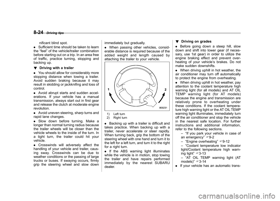
. Backing up with a trailer is difficult and
takes practice. When backing up with a
trailer, never accelerate or steer rapidly.
When turning back, grip the bottom of the
steering wheel with one hand and turn it to
the left for a left turn, and turn it to the right
for a right turn. . If the ABS warning light illuminates
while the vehicle is in motion, stop towing
the trailer and have repairs performed
immediately by the nearest SUBARU
dealer. !
Driving on grades
. Before going down a steep hill, slow
down and shift into lower gear (if neces-
sary, use 1st gear) in order to utilize the
engine braking effect and prevent over-
heating of your vehicle ’s brakes. Do not
make sudden downshifts. . When driving uphill in hot weather, the
air conditioner may turn off automatically
to protect the engine from overheating. . When driving uphill in hot weather, pay
attention to the coolant temperature high
warning light (for all models) and AT OIL
TEMP warning light (for AT models)
because the engine and transmission are
relatively prone to overheating under
these conditions. If the coolant tempera-
ture high warning light or the AT OIL TEMP
warning light illuminates, immediately turn
off the air conditioner and stop the vehicle
in the nearest safe location. For further
instructions and additional information,
refer to the following sections.
–“If you park your vehicle in case of
an emergency ”F 9-2
–“ Engine overheating ”F 9-12
–“ Coolant temperature low indicator
light/Coolant temperature high warn-
ing light ”F 3-13
–“ AT OIL TEMP warning light (AT
models) ”F 3-14
. If your vehicle has an automatic trans-
Page 313 of 402
11-8Maintenance and service
Engine oil NOTE .The engine oil consumption rate is
not stabilized, and therefore cannot be
determined until the vehicle has tra-
veled at least several thousand miles
(kilometers). Even after break-in, when
the vehicle is used under severe driv-
ing conditions such as those men-
tionedintheWarrantyandMainte-
nance Booklet, engine oil is consumed
or deteriorated more quickly than un-
der normal driving conditions. If you
drive your vehicle under these severe
conditions, you should check the oil
level at least at every second fuel fill-up
time, and change the oil more fre-
quently. Please refer to the Warranty
and Maintenance Booklet for more de-tails.. If the oil consumption rate seems
abnormally high after the break-in
period, for example more than 1 quart
per 1,200 miles or 1 liter per 2,000
kilometers, contact your SUBARU deal-
er. &
Checking the oil level
Check the engine oil level at each fuelstop.
1. Park the vehicle on a level surface and
stop the engine.
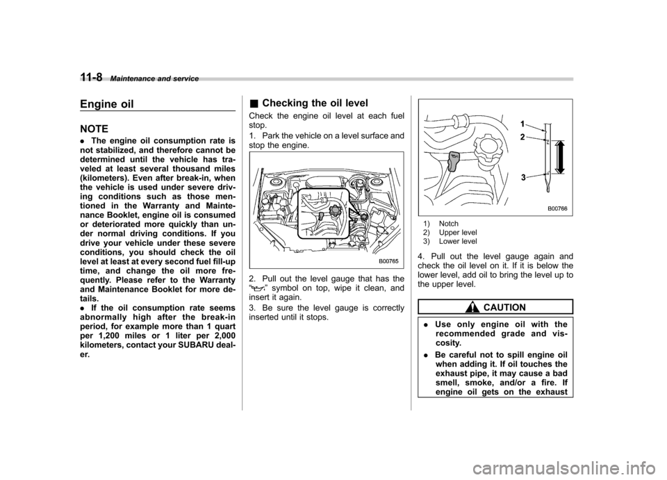
2. Pull out the level gauge that has the “” symbol on top, wipe it clean, and
insert it again.
3. Be sure the level gauge is correctly
inserted until it stops.
1) Notch
2) Upper level
3) Lower level
4. Pull out the level gauge again and
check the oil level on it. If it is below the
lower level, add oil to bring the level up to
the upper level.
CAUTION
. Use only engine oil with the
recommended grade and vis-
cosity.
. Be careful not to spill engine oil
when adding it. If oil touches the
exhaust pipe, it may cause a bad
smell, smoke, and/or a fire. If
engine oil gets on the exhaust
Page 314 of 402
pipe, be sure to wipe it off.
If you check the oil level just after stopping
the engine, wait a few minutes for the oil to
drain back into the oil pan before checking
the level.
Just after driving or while the engine is
warm, the engine oil level reading may be
in a range between the upper level and
the notch mark. This is caused by thermal
expansion of the engine oil.
To prevent overfilling the engine oil, do not
add any additional oil above the upper
level when the engine is cold. & Changing the oil and oil filter
Change the oil and oil filter according to
the maintenance schedule in the “War-
ranty and Maintenance Booklet ”.
The engine oil and oil filter must be
changed more frequently than listed in
the maintenance schedule when driving
on dusty roads, when short trips are
frequently made, or when driving in
extremely cold weather.
1. Warm up the engine by letting the
engine idle for approximately 10 minutes
to ease draining the engine oil.
2. Park the vehicle on a level surface and
stop the engine.
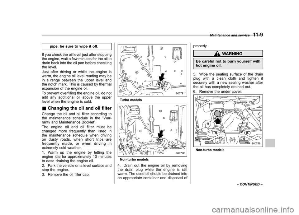
3. Remove the oil filler cap.
Turbo models
Non-turbo models
4. Drain out the engine oil by removing
the drain plug while the engine is still
warm. The used oil should be drained into
an appropriate container and disposed of properly.
WARNING
Be careful not to burn yourself with
hot engine oil.
5. Wipe the seating surface of the drain
plug with a clean cloth and tighten it
securely with a new sealing washer after
the oil has completely drained out.
6. Remove the under cover.
Non-turbo models Maintenance and service
11-9
– CONTINUED –
Page 317 of 402
11-12Maintenance and service
&Recommended grade and
viscosity under severe driv-
ing conditions
If the vehicle is used in desert areas, in
areas with very high temperatures, or is
used for heavy-duty applications, use of
oil with the following grade and viscosities
is recommended.
API classification SM (or SL): SAE viscosity No.: 30, 40, 10W-50,
20W-40, 20W-50
& Synthetic oil
You can use synthetic engine oil that
meets the same requirements given for
conventional engine oil. When using
synthetic oil, you must use oil of the same
classification, viscosity and grade shown
in this Owner ’s Manual, and must follow
the oil and filter changing intervals shown
in the maintenance schedule. Cooling system
WARNING
Never attempt to remove the radia-
tor cap until the engine has been
shut off and has cooled down
completely. Since the coolant is
under pressure, you may suffer
serious burns from a spray of boil-
ing hot coolant when the cap isremoved.
CAUTION
. Vehicles are filled at the factory
with SUBARU Super Coolant that
does not require the first change
for 11 years/137,500 miles (11
years/220,000 km). This coolant
should not be mixed with any
other brand or type of coolant
during this period. Mixing with a
different coolant will reduce the
life of the coolant. Should it be
necessary to top up the coolant
for any reason, use only
SUBARU Super Coolant.
If the SUBARU Super Coolant is
diluted with another brand or
type, the maintenance interval is shortened to that of the mixingcoolant.
. Do not splash the engine coolant
over painted parts. The alcohol
contained in the engine coolant
may damage the paint surface.
& Cooling fan, hose and con- nections
Your vehicle employs an electric cooling
fan which is thermostatically controlled to
operate when the engine coolant reaches
a specific temperature.
If the radiator cooling fan does not operate
even when the coolant temperature high
warning light blinks or illuminates in RED,
the cooling fan circuit may be defective.
Refer to “Coolant temperature low indica-
tor light/Coolant temperature high warninglight ”F 3-13.
Check the fuse and replace it if necessary.
If the fuse is not blown, have the cooling
system checked by your SUBARU dealer.
Refer to “Fuses ”F 11-44 and “Fuse panel
located in the engine compartment ”F 12-
8.
If frequent addition of coolant is neces-
sary, there may be a leak in the engine
cooling system. It is recommended that
Page 318 of 402
the cooling system and connections be
checked for leaks, damage, or looseness. &Engine coolant
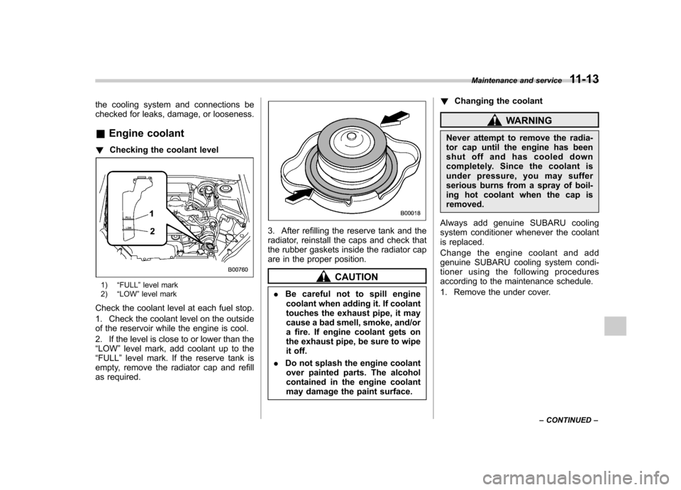
! Checking the coolant level
1) “FULL ”level mark
2) “LOW ”level mark
Check the coolant level at each fuel stop.
1. Check the coolant level on the outside
of the reservoir while the engine is cool.
2. If the level is close to or lower than the “ LOW ”level mark, add coolant up to the
“ FULL ”level mark. If the reserve tank is
empty, remove the radiator cap and refill
as required.
3. After refilling the reserve tank and the
radiator, reinstall the caps and check that
the rubber gaskets inside the radiator cap
are in the proper position.
CAUTION
. Be careful not to spill engine
coolant when adding it. If coolant
touches the exhaust pipe, it may
cause a bad smell, smoke, and/or
a fire. If engine coolant gets on
the exhaust pipe, be sure to wipe
it off.
. Do not splash the engine coolant
over painted parts. The alcohol
contained in the engine coolant
may damage the paint surface. !
Changing the coolant
WARNING
Never attempt to remove the radia-
tor cap until the engine has been
shut off and has cooled down
completely. Since the coolant is
under pressure, you may suffer
serious burns from a spray of boil-
ing hot coolant when the cap isremoved.
Always add genuine SUBARU cooling
system conditioner whenever the coolant
is replaced.
Change the engine coolant and add
genuine SUBARU cooling system condi-
tioner using the following procedures
according to the maintenance schedule.
1. Remove the under cover. Maintenance and service
11-13
– CONTINUED –