2010 SKODA ROOMSTER fold seats
[x] Cancel search: fold seatsPage 66 of 231

Seats and Storage65
Using the system
Safety
Driving Tips
General Maintenance
Breakdown assistance
Praktik
Technical Data
The luggage compartment cover
You can use the luggage compartment cover behind the head
restraints for storing light and soft items.Fig. 60 Removal of the luggage compartmen t cover / Luggage compartment cover in the
lower positionThe luggage compartment cover can be removed as required if one must transport
bulky goods.
– Unhook the support straps fig. 60 .
– Slightly raise the luggage compartment cover.
– Remove the luggage compartment cover from the holder by pulling to the rear or with adequate blows to th e bottom side of the cover.
– Install again by pushing the luggage compartment cover forwards into the holder and hanging the support straps on the boot lid.
The luggage compartment cover can also be put into the lower position on the
supporting elements fig. 60 on the right.
The procedure of installing or removing is identical.
The luggage compartment cover is foreseen for storage of small objects of up to 2.5 kg.
in weight.
WARNING
No objects should be placed on the luggage compartment cover, the vehicle
occupants could be endangered if th ere is sudden braking or the vehicle
collides with something.
Caution
Please ensure that the heating elements of the rear window heater are not damaged
as a result of objects placed in this area.
Note
When opening the boot lid, lift the luggage compartment cover - risk that objects
placed in this area can slip forward!Static separation net*Fig. 61 Use of the static separation net be hind the rear seats / behind the front seatsInstall the static separation net behind the front seats or the rear seats.Install the static separation net behind the rear seats– Remove the luggage compartment cover.
– Take the separation net out of the bag.
– Unfold both parts of the cross rod until they are heard to engage.
A1
A2
A2
A1
s16g.4.book Page 65 Wednesday, February 10, 2010 3:53 PM
Page 67 of 231
Seats and Storage
66
– Insert the cross rod into the mount first on the one side and push the cross rod
forward. In the same way, fix the cross rod to the other side of the vehicle, mount
page 65, fig. 61 .
– Hang the carabines at the ends of the st rap into the lashing eyes behind the rear
seats.
– Pull the strap through the tensioning clasp, first of all on the one side and then on
the other side.Remove the static separation net behind the rear seats– Slacken the bands on both sides and take off the carabines page 65, fig. 61 .
– Push the cross rod first of all on the one side and then on the other side towards
the rear.
– Take the cross rod out of the mounts .Pack static separation net– Press the red button of the joint - so that it releases.
– Put the separation net folded together in the bag and close it.
– Attach the bag with the aid of the plastic carabines to the eyes on the left and right luggage compartment trim panel.
Installing and removing the static se paration net behind the front seats page 65,
fig. 61 on the right is carried out analogously as behind the rear seats. Use the eyes
behind the front seats to attach the carabi nes. Remove the rear seats to enlarge the
luggage compartment.
Installing and removing the static separation net behind the rear seats with variable
loading floor* page 66 is carried out analogously as behind the rear seats without
variable loading floor. Use the lower eyes at the fixing wedges on the front part of the
variable loading floor in or der to attach the carabines.
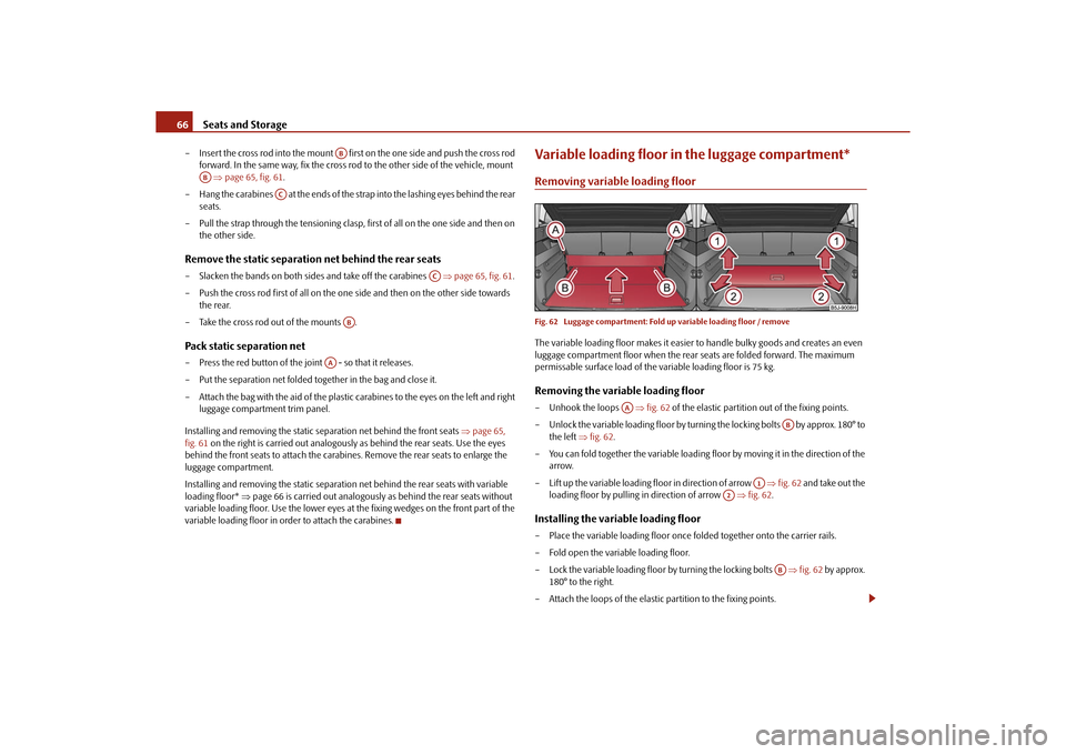
Variable loading floor in the luggage compartment*Removing variable loading floorFig. 62 Luggage compartment: Fold up variable loading floor / removeThe variable loading floor makes it easier to handle bulky goods and creates an even
luggage compartment floor when the rear seats are folded forward. The maximum
permissable surface load of the variable loading floor is 75 kg.Removing the variable loading floor– Unhook the loops fig. 62 of the elastic partition out of the fixing points.
– Unlock the variable loading floor by turnin g the locking bolts by approx. 180° to
the left fig. 62 .
– You can fold together the variable loading floor by moving it in the direction of the
arrow.
– Lift up the variable loading floor in direction of arrow fig. 62 and take out the
loading floor by pulling in direction of arrow fig. 62 .Installing the variable loading floor– Place the variable loading floor once folded together onto the carrier rails.
– Fold open the variable loading floor.
– Lock the variable loading floor by turning the locking bolts fig. 62 by approx.
180° to the right.
– Attach the loops of the elastic partition to the fixing points.
AB
AB
AC
AC
AB
AA
AA
AB
A1
A2
AB
s16g.4.book Page 66 Wednesda y, February 10, 2010 3:53 PM
Page 69 of 231
Seats and Storage
68
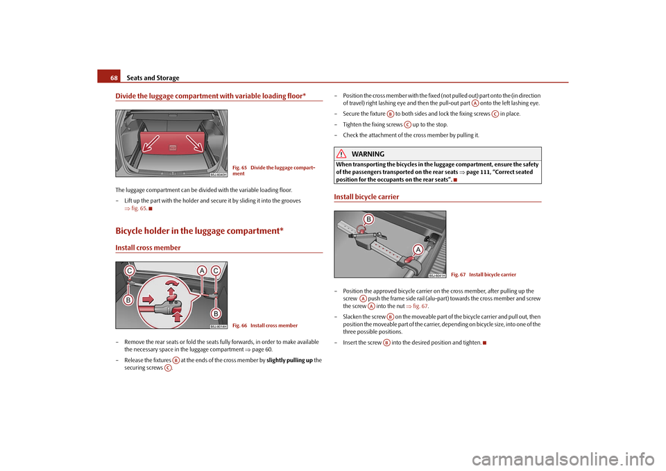
Divide the luggage compartment with variable loading floor*The luggage compartment can be divided with the variable loading floor.
– Lift up the part with the holder and secure it by sliding it into the grooves
fig. 65 .Bicycle holder in the luggage compartment*Install cross member– Remove the rear seats or fold the seats fully forwards, in order to make available
the necessary space in the luggage compartment page 60.
– Release the fixtures at the ends of the cross member by slightly pulling up the
securing screws . – Position the cross member with the fixed (not
pulled out) part onto the (in direction
of travel) right lashing eye and then the pull-out part onto the left lashing eye.
– Secure the fixture to both sides an d lock the fixing screws in place.
– Tighten the fixing screws up to the stop.
– Check the attachment of the cross member by pulling it.
WARNING
When transporting the bicycles in the luggage compartment, ensure the safety
of the passengers transported on the rear seats page 111, “Correct seated
position for the occupants on the rear seats”.Install bicycle carrier– Position the approved bicycle carrier on the cross member, after pulling up the
screw push the frame side rail (alu-part) towards the cross member and screw
the screw into the nut fig. 67 .
– Slacken the screw on the moveable part of the bicycle carrier and pull out, then
position the moveable part of the carrier, depending on bicycle size, into one of the
three possible positions.
– Insert the screw into the desired position and tighten.
Fig. 65 Divide the luggage compart-
mentFig. 66 Install cross member
AB
AC
AA
AB
AC
AC
Fig. 67 Install bicycle carrier
AAAA
ABAB
s16g.4.book Page 68 Wednesda y, February 10, 2010 3:53 PM
Page 70 of 231
Seats and Storage69
Using the system
Safety
Driving Tips
General Maintenance
Breakdown assistance
Praktik
Technical Data
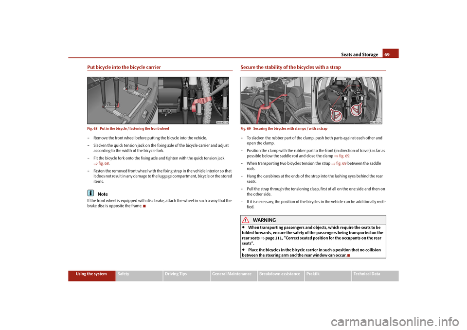
Put bicycle into the bicycle carrierFig. 68 Put in the bicycle / fastening the front wheel– Remove the front wheel before putti ng the bicycle into the vehicle.
– Slacken the quick tension jack on the fixi ng axle of the bicycle carrier and adjust
according to the width of the bicycle fork.
– Fit the bicycle fork onto the fixing axle and tighten with the quick tension jack
fig. 68 .
– Fasten the removed front wheel with the fixing strap in the vehicle interior so that it does not result in any damage to the luggage compartment, bicycle or the stored
items.
Note
If the front wheel is equipped with disc brak e, attach the wheel in such a way that the
brake disc is opposite the frame.
Secure the stability of the bicycles with a strapFig. 69 Securing the bicycles with clamps / with a strap– To slacken the rubber part of the clamp, push both parts against each other and
open the clamp.
– Position the clamp with the rubber part to the front (in direction of travel) as far as possible below the saddle rod and close the clamp fig. 69 .
– When transporting two bi cycles tension the strap fig. 69 between the saddle
rods.
– Hang the carabines at the ends of the strap into the lashing eyes behind the rear seats.
– Pull the strap through the tensioning clasp, first of all on the one side and then on the other side.
– If it is necessary, the position of the bicycles in the vehicle can be additionally recti- fied.
WARNING
When transporting passengers and objects, which require the seats to be
folded forwards, ensure the safety of the passengers being transported on the
rear seats page 111, “Correct seated position for the occupants on the rear
seats”.
Place the bicycles in the bicycle carrier in such a position that no collision
between the steering arm and the rear window can occur.
s16g.4.book Page 69 Wednesda y, February 10, 2010 3:53 PM
Page 75 of 231

Seats and Storage
74
Storage compartments on the front passenger side*On some vehicles, the storage compartments are not equipped with lids.Opening and closing the storage compartments on the front passenger
side– Pull the handle of the lid in direction of arrow fig. 77 and fold it open.
– Swivel the flap until it is heard to lock.
A pin holder is located on the inside of the flap.
WARNING
The storage compartment must always be closed when driving for safety
reasons.
Cooling of storage compartment on front passenger side*
The storage compartment ca n be fitted for vehicles with an air-condi-
tioning system with a closable inlet for cooled air.– You can switch the cooling system on or off using the control dial fig. 78 .
Opening the air inlet when the air conditioning system is on causes fresh or interior air
to flow into the storage compartment.
We recommend that you switch off the cooling if it is operating in the heating mode or
if you are not using the cooling system for the storage compartment.Storage compartment on the driver's sideUnlockable compartment below the steering wheel on the left.
Fig. 77 Dash panel: Storage compart-
ments on the front passenger side
Fig. 78 Storage compartment: Using
cooling systemFig. 79 Dash panel: Storage compart-
ment on the driver's side
s16g.4.book Page 74 Wednesda y, February 10, 2010 3:53 PM
Page 76 of 231
Seats and Storage75
Using the system
Safety
Driving Tips
General Maintenance
Breakdown assistance
Praktik
Technical Data
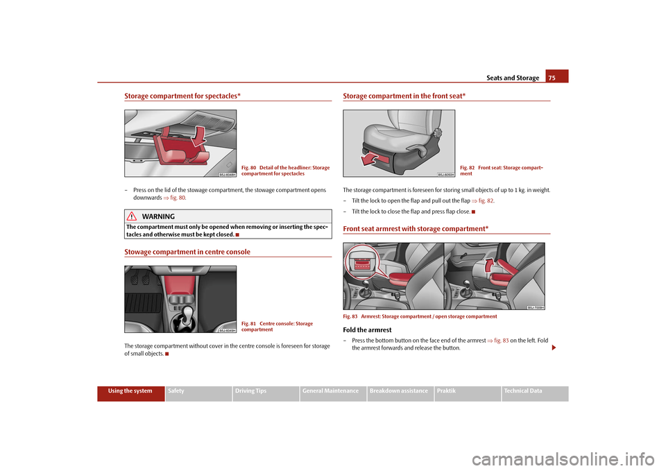
Storage compartment for spectacles*– Press on the lid of the stowage comp artment, the stowage compartment opens
downwards fig. 80 .
WARNING
The compartment must only be opened when removing or inserting the spec-
tacles and otherwise must be kept closed.Stowage compartment in centre consoleThe storage compartment without cover in the centre console is foreseen for storage
of small objects.
Storage compartment in the front seat*The storage compartment is foreseen for storing small objects of up to 1 kg. in weight.
– Tilt the lock to open the flap and pull out the flap fig. 82 .
– Tilt the lock to close the flap and press flap close.Front seat armrest with storage compartment*Fig. 83 Armrest: Storage compartment / open storage compartmentFold the armrest– Press the bottom button on the face end of the armrest fig. 83 on the left. Fold
the armrest forwards and release the button.
Fig. 80 Detail of the headliner: Storage
compartment for spectaclesFig. 81 Centre console: Storage
compartment
Fig. 82 Front seat: Storage compart-
ment
s16g.4.book Page 75 Wednesda y, February 10, 2010 3:53 PM
Page 77 of 231

Seats and Storage
76
Opening storage compartment
– Press the top button and fold up the cover of the storage compartment page 75,
fig. 83 on the right.
Note
The moving space of the arms can be restricted if the armrest is folded down. In city
traffic the armrest should not be folded down.Storage compartment in the front doorsA bottle holder is located in the area of the storage compartment for the front
doors.
WARNING
Use the area fig. 84 of the storage compartment only for storing objects
which do not project so that the effectiveness of the side airbag is not
impaired.
Storage compartments in the luggage compartmentStorage compartments are located on bo th sides of the luggage compartment
fig. 85 .
The storage compartments are intended for storing small objects of up to 1.5 kg in
weight.Flexible storage compartment*A flexible storage compartmen t is located on the right side of the luggage compart-
ment. The flexible storage compartment is foreseen for storing small objects of up to 8
kg. in weight.Removing– Take hold of the flexible storage compartment at both upper corners.
Fig. 84 Stowage compartment in door
panel
AB
AA
Fig. 85 Storage compartments in the
side trim panelFig. 86 Flexible storage compartment
s16g.4.book Page 76 Wednesda y, February 10, 2010 3:53 PM
Page 224 of 231
Index223
Using the system
Safety
Driving Tips
General Maintenance
Breakdown assistance
Praktik
Technical Data
Exterior mirror heater . . . . . . . . . . . . . . . . . . . . . . . . . 55
FFastening elements . . . . . . . . . . . . . . . . . . . . . . . . . . . 63
First-aid box . . . . . . . . . . . . . . . . . . . . . . . . . . . . . . . . . 181
Fixing net . . . . . . . . . . . . . . . . . . . . . . . . . . . . . . . . . . . . . 64
Fog lights . . . . . . . . . . . . . . . . . . . . . . . . . . . . . . . . 48, 198
Warning light . . . . . . . . . . . . . . . . . . . . . . . . . . . . . 27
Fog lights with the function CORNER . . . . . . . . . . . 48
Folding seats forwards . . . . . . . . . . . . . . . . . . . . . . . . 60
Force limiter of the power windows . . . . . . . . . . . . 44
Front airbag . . . . . . . . . . . . . . . . . . . . . . . . . . . . . . . . . 119
Front armrest . . . . . . . . . . . . . . . . . . . . . . . . . . . . . . . . . 75
Front headlight . . . . . . . . . . . . . . . . . . . . . . . . . . . . . . 197
Fuel . . . . . . . . . . . . . . . . . . . . . . . . . . . . . . . . . . . . . . . . . 158 Diesel fuel . . . . . . . . . . . . . . . . . . . . . . . . . . . . . . . 158
Fuel gauge . . . . . . . . . . . . . . . . . . . . . . . . . . . . . . . . 16
Petrol . . . . . . . . . . . . . . . . . . . . . . . . . . . . . . . . . . . 158
Warning light . . . . . . . . . . . . . . . . . . . . . . . . . . . . . 28
Fuel consumption . . . . . . . . . . . . . . . . . . . . . . . 20, 142 Saving energy . . . . . . . . . . . . . . . . . . . . . . . . . . . . 142
Fuel gauge . . . . . . . . . . . . . . . . . . . . . . . . . . . . . . . . . . . 16
Fuel reserve Warning light . . . . . . . . . . . . . . . . . . . . . . . . . . . . . 28
Full wheel trim . . . . . . . . . . . . . . . . . . . . . . . . . . . . . . . 184
Fuse Assignment . . . . . . . . . . . . . . . . . . . . . . . . . . . . . . 192
Fuses . . . . . . . . . . . . . . . . . . . . . . . . . . . . . . . . . . . . . . . 191
GGearbox mechanical . . . . . . . . . . . . . . . . . . . . . . . . . . . . . . . 90
General view Cockpit . . . . . . . . . . . . . . . . . . . . . . . . . . . . . . . . . . . . 9
Glow plug system . . . . . . . . . . . . . . . . . . . . . . . . . . . . . 89 Warning light . . . . . . . . . . . . . . . . . . . . . . . . . . . . . . 28
GSM . . . . . . . . . . . . . . . . . . . . . . . . . . . . . . . . . . . . . . . . 101HHalogen projector headlights with cornering light function . . . . . . . . . . . . . . . . . . . . . . . . . . . . . . . . . 47
Handbrake . . . . . . . . . . . . . . . . . . . . . . . . . . . . . . . . . . . 90
Hazard warning light system . . . . . . . . . . . . . . . . . . . 49 Warning light . . . . . . . . . . . . . . . . . . . . . . . . . . . . . . 26
Head airbag . . . . . . . . . . . . . . . . . . . . . . . . . . . . . . . . . 123
Head restraint . . . . . . . . . . . . . . . . . . . . . . . . . . . . . . . . 58
Headlight cleaning system . . . . . . . . . . . . . . . . . . . . . 54
Headlight flasher . . . . . . . . . . . . . . . . . . . . . . . . . . . . . . 50
Headlights Fog lights . . . . . . . . . . . . . . . . . . . . . . . . . . . . . . . . . 48
Headlight cleaning system . . . . . . . . . . . . . . . . . . 54
Heated windscreen washer nozzles . . . . . . . . . . . . . 53
Heating . . . . . . . . . . . . . . . . . . . . . . . . . . . . . . . . . . . . . . 79
Heating the front seats . . . . . . . . . . . . . . . . . . . . . . . . 59
Horn . . . . . . . . . . . . . . . . . . . . . . . . . . . . . . . . . . . . . . . . . . 9IIgnition . . . . . . . . . . . . . . . . . . . . . . . . . . . . . . . . . . . . . . . 87
Ignition lock . . . . . . . . . . . . . . . . . . . . . . . . . . . . . . . . . . 87 Immobiliser . . . . . . . . . . . . . . . . . . . . . . . . . . . . . . . . . . . 35
Information display . . . . . . . . . . . . . . . . . . . . . . . . . . . 22
Instrument cluster . . . . . . . . . . . . . . . . . . . . . . . . . . . . . 15
Interior light
Luggage compartment . . . . . . . . . . . . . . . . . . . . . 52
Interior lighting front . . . . . . . . . . . . . . . . . . . . . . . . . . . . . . . . . . . . . . 51
rear . . . . . . . . . . . . . . . . . . . . . . . . . . . . . . . . . . . . . . . 51
Interior monitor . . . . . . . . . . . . . . . . . . . . . . . . . . . . . . . 42
Intermittent wiping . . . . . . . . . . . . . . . . . . . . . . . . . . . . 53
ISOFIX . . . . . . . . . . . . . . . . . . . . . . . . . . . . . . . . . . . . . . 131
ISOFIX system . . . . . . . . . . . . . . . . . . . . . . . . . . . . . . . 131
JJacking points . . . . . . . . . . . . . . . . . . . . . . . . . . . . . . . 185
Jump-starting . . . . . . . . . . . . . . . . . . . . . . . . . . . 186, 187KKey . . . . . . . . . . . . . . . . . . . . . . . . . . . . . . . . . . . . . . . . . . 34LLashing eyes . . . . . . . . . . . . . . . . . . . . . . . . . . . . . . . . . . 63
Leather care . . . . . . . . . . . . . . . . . . . . . . . . . . . . . . . . 156
Lifting jack . . . . . . . . . . . . . . . . . . . . . . . . . . . . . . . . . . 181
Lighting of the interior of the vehicle front . . . . . . . . . . . . . . . . . . . . . . . . . . . . . . . . . . . . . . 51
rear . . . . . . . . . . . . . . . . . . . . . . . . . . . . . . . . . . . . . . . 51
Lights converting/masking over . . . . . . . . . . . . . . . . . 146
Range adjustment . . . . . . . . . . . . . . . . . . . . . . . . . 49
s16g.4.book Page 223 Wednesda y, February 10, 2010 3:53 PM