Page 207 of 230

PETROL INJECTION
Fault finding - Interpretation of parameters
17B
17B - 207
PETROL INJECTION
Fault finding - Interpretation of parameters
17B
17B - 207V9 MR-372-J84-17B050$705.mif
S3000 Injection
Program No.: AD
Vdiag No.: 4C / 54
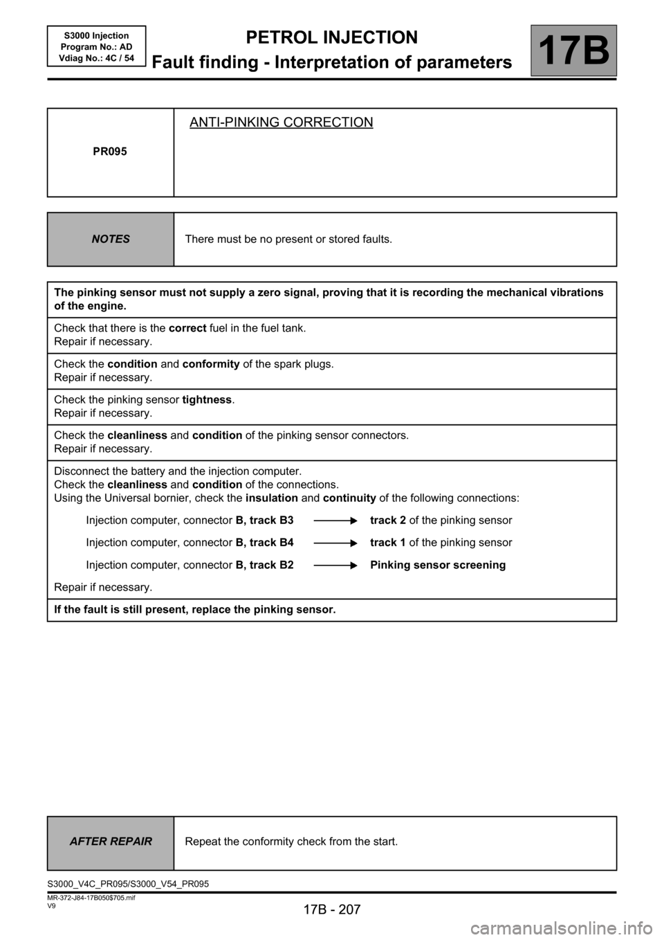
PR095
ANTI-PINKING CORRECTION
NOTESThere must be no present or stored faults.
The pinking sensor must not supply a zero signal, proving that it is recording the mechanical vibrations
of the engine.
Check that there is the correct fuel in the fuel tank.
Repair if necessary.
Check the condition and conformity of the spark plugs.
Repair if necessary.
Check the pinking sensor tightness.
Repair if necessary.
Check the cleanliness and condition of the pinking sensor connectors.
Repair if necessary.
Disconnect the battery and the injection computer.
Check the cleanliness and condition of the connections.
Using the Universal bornier, check the insulation and continuity of the following connections:
Injection computer, connectorB, track B3 track 2 of the pinking sensor
Injection computer, connectorB, track B4 track 1 of the pinking sensor
Injection computer, connectorB, track B2 Pinking sensor screening
Repair if necessary.
If the fault is still present, replace the pinking sensor.
AFTER REPAIRRepeat the conformity check from the start.
S3000_V4C_PR095/S3000_V54_PR095
Page 209 of 230

PETROL INJECTION
Fault finding - Interpretation of parameters
17B
17B - 209
PETROL INJECTION
Fault finding - Interpretation of parameters
17B
17B - 209V9 MR-372-J84-17B050$705.mif
S3000 Injection
Program No.: AD
Vdiag No.: 4C / 54
PR098
CONTINUED
If the fault is still present, replace the upstream oxygen sensor.
If the fault has still not been cured, continue with the checks.
Check:
– the condition of the air filter,
– that the air inlet circuit is not blocked,
– the condition and conformity of the spark plugs,
– that the catalytic converter is not clogged,
– the sealing between the throttle valve and inlet manifold,
– the manifold pressure sensor sealing,
– the fuel vapour absorber bleed, which must not be jammed open,'
– the fuel vapour absorber bleed system sealing,
– the brake servo system sealing,
– the cylinder head oil vapour recovery system sealing,
– the sealing between the inlet manifold and cylinder head,
– the exhaust pipe sealing between the cylinder head and catalytic converter.
– the fuel flow rate and pressure.
If the idle speed is not stable, check:
– the timing adjustment,
– the hydraulic tappets if there is camshaft noise (see MR 364 or 370 Mechanics, 11A, Top and front of engine),
– the cylinder compressions.
Drive the vehicle to check the repair.
AFTER REPAIRRepeat the conformity check from the start.
Page 219 of 230

PETROL INJECTION
Fault finding - Test
17B
PETROL INJECTION
Fault finding - Test
17B
17B-219V9 MR-372-J84-17B050$846.mif
S3000 Injection
Program No.: AD
Vdiag No.: 4C / 54
TEST 2 Camshaft dephaser solenoid valve
Special NoteTo apply this method, it is necessary to use the special tool Elé. 1793, available in the
Parts Department catalogue.
Vdiag 4C only
– Disconnect the solenoid valve connector.
– Measure the electrical resistance between the
terminals of the solenoid valve at 20°C.
Is the electrical resistance of the solenoid valve
between 6.7Ω and 7.7Ω?
YES
Use the tool Elé. 1793 in accordance with the
method below:
– connect the tool to the solenoid valve and to
the vehicle battery,
– start the engine and maintain idle speed,
– actuate the solenoid valve with the tool
(by pressing on the button).
Does the engine stall and/or is the idle speed
very unstable?
NO
– Switch off the engine.
– Use the tool Elé. 1793 to operate the solenoid
valve. Press several times successively to hear
the solenoid valve.
NO– The solenoid valve is faulty.
– Replace the solenoid valve with a new one.
YES– The pulley-dephaser and the solenoid valve
operate.
– Check the injection computer, camshaft
sensor, TDC sensor and their wiring and
respective connections.
S3000_V4C_TEST2/S3000_V54_TEST2
Page 220 of 230
PETROL INJECTION
Fault finding - Test
17B
PETROL INJECTION
Fault finding - Test
17B
17B-220V9 MR-372-J84-17B050$846.mif
TEST 2
CONTINUED
Can the solenoid valve be heard operating?
NO
– Remove the solenoid valve from the engine.
– Use the tool Elé. 1793 to operate the solenoid
valve. Press several times successively to see
the valve move.
Does the valve move?
NO
– The solenoid valve is faulty.
– Replace the solenoid valve with a new one.YES– The pulley-dephaser is faulty.
– Replace the pulley-dephaser with a new
one.
YES– The pulley-dephaser is faulty.
– Replace the pulley-dephaser with a new
one.
S3000 Injection
Program No.: AD
Vdiag No.: 4C / 54
Page 221 of 230
PETROL INJECTION
Fault finding - Test
17B
PETROL INJECTION
Fault finding - Test
17B
17B-221V9 MR-372-J84-17B050$846.mif
S3000 Injection
Program No.: AD
Vdiag No.: 4C / 54
TEST 3 Camshaft dephaser solenoid valve
NOTESVdiag 54 only
Disconnect the solenoid valve connector.
Measure the electrical resistance between the
terminals of the solenoid valve at 20°C.
Is the electrical resistance of the solenoid valve
between 6.7 Ω and 7.7 Ω?
YES
Start the engine and set it to idle speed.
Run command AC254 Camshaft dephaser: ON/
OFF control (engine oil temperature between
10°C and 70°C).
Does the engine stall and/or is the idle speed
unstable?
NO
Switch off the engine.
Run command AC253: Camshaft dephaser:
Normal control
NOThe solenoid valve is faulty.
Replace the solenoid valve.
YESThe pulley-dephaser and the solenoid valve
are working.
Check the injection computer, the camshaft
sensor, the TDC sensor and their respective
wiring and connections.
S3000_V4C_TEST3/S3000_V54_TEST3
Page 223 of 230

PETROL INJECTION
Fault finding - Customer complaints
17B
17B-223
PETROL INJECTION
Fault finding - Customer complaints
17B
17B-223V9 MR-372-J84-17B050$893.mif
S3000 Injection
Program No.: AD
Vdiag No.: 4C / 54PETROL INJECTION
Fault finding - Customer complaints
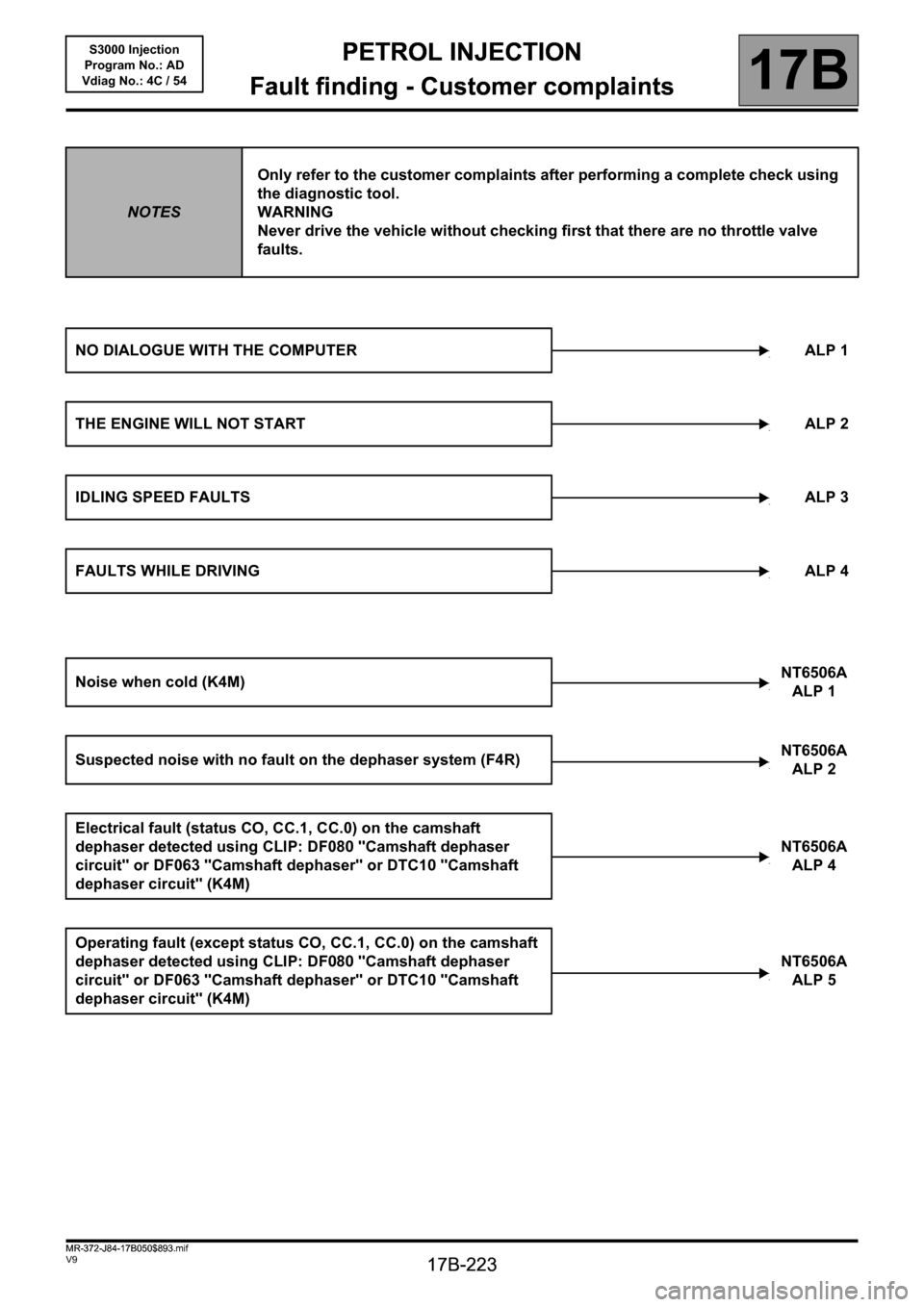
NOTESOnly refer to the customer complaints after performing a complete check using
the diagnostic tool.
WARNING
Never drive the vehicle without checking first that there are no throttle valve
faults.
NO DIALOGUE WITH THE COMPUTER ALP 1
THE ENGINE WILL NOT STARTALP 2
IDLING SPEED FAULTSALP 3
FAULTS WHILE DRIVINGALP 4
Noise when cold (K4M)NT6506A
ALP 1
Suspected noise with no fault on the dephaser system (F4R)NT6506A
ALP 2
Electrical fault (status CO, CC.1, CC.0) on the camshaft
dephaser detected using CLIP: DF080 "Camshaft dephaser
circuit" or DF063 "Camshaft dephaser" or DTC10 "Camshaft
dephaser circuit" (K4M)NT6506A
ALP 4
Operating fault (except status CO, CC.1, CC.0) on the camshaft
dephaser detected using CLIP: DF080 "Camshaft dephaser
circuit" or DF063 "Camshaft dephaser" or DTC10 "Camshaft
dephaser circuit" (K4M) NT6506A
ALP 5
MR-372-J84-17B050$893.mif
Page 228 of 230

PETROL INJECTION
Fault finding - Fault Finding Chart
17B
17B-228
PETROL INJECTION
Fault finding - Fault Finding Chart
17B
17B-228V9 MR-372-J84-17B050$940.mif
S3000 Injection
Program No.: AD
Vdiag No.:4C / 54
ALP 2 The engine will not start
NOTESFollow ALP 2 after a complete check with the diagnostic tool.
WARNING
Never drive the vehicle without checking first that there are no throttle valve
faults.
If the starter motor does not engage, there may be an engine immobiliser fault.
Carry out fault finding on the UCH (see87B, Passenger Compartment Connection Unit).
Check the condition of the battery.
Check the cleanliness, condition and tightness of the battery terminals.
Check that the battery is correctly earthed to the vehicle bodywork.
Check that the + battery leads are correctly connected.
Check that the starter motor is properly connected.
Check the starter is working properly (see Technical Note 6014A Checking the charging circuit).
Check the condition and conformity of the spark plugs.
Check the mounting, cleanliness and condition of the flywheel signal sensor.
Check the flywheel signal sensor air gap.
Check the condition of the flywheel.
Check that the air filter is not clogged.
Check that the air inlet circuit is not blocked.
Check that there is fuel in the tank (fuel sender fault).
Check that the tank vent is not blocked.
Check that the fuel is of the correct type.
Check that there are no leaks in the fuel system, from the tank to the injectors.
Check that there are no kinked hoses (especially after a removal operation).
Check the fuel flow rate and pressure.
Check the sealing of the injectors, and that they are working properly.
Check that the exhaust system is not blocked and the catalytic converter not clogged.
Check the timing setting.
Check the cylinder compressions.
Check the hydraulic tappets if there is camshaft noise.
AFTER REPAIRRepeat the conformity check from the start.
S3000_V4C_ALP2/S3000_V54_ALP2