2010 NISSAN TIIDA periodic maintenance
[x] Cancel search: periodic maintenancePage 983 of 3745

CO-1
ENGINE
C
DE
F
G H
I
J
K L
M
SECTION CO
A
CO
N
O P
CONTENTS
ENGINE COOLING SYSTEM
HR16DE
PRECAUTION ....... ........................................
3
PRECAUTIONS .............................................. .....3
Precaution for Supplemental Restraint System
(SRS) "AIR BAG" and "SEAT BELT PRE-TEN-
SIONER" ............................................................. ......
3
Precaution Necessary for Steering Wheel Rota-
tion After Battery Disconnect ............................... ......
3
Precaution for Liquid Gasket .....................................4
PREPARATION ............................................6
PREPARATION .............................................. .....6
Special Service Tool ........................................... ......6
Commercial Service Tool ..........................................6
SYMPTOM DIAGNOSIS ...............................8
OVERHEATING CAUSE ANALYSIS ............. .....8
Troubleshooting Chart ...............................................8
FUNCTION DIAGNOSIS .. ............................10
DESCRIPTION ............................................... ....10
Engine Cooling System ....................................... ....10
Engine Cooling System Schematic .........................11
ON-VEHICLE MAINTENANCE ....................12
ENGINE COOLANT ....................................... ....12
Inspection ............................................................ ....12
Changing Engine Coolant .......................................12
RADIATOR .........................................................15
Checking Radiator Cap ....................................... ....15
Checking Radiator ...................................................15
ON-VEHICLE REPAIR .................................17
RADIATOR ..................................................... ....17
Component .......................................................... ....17
Removal and Installation ..................................... ....17
COOLING FAN ..................................................19
Component (Models with A/C) .................................19
Component (Models without A/C) ............................19
Removal and Installation .........................................20
Disassembly and Assembly .....................................20
WATER PUMP ..................................................21
Exploded View .........................................................21
Removal and Installation .........................................21
Inspection ................................................................22
THERMOSTAT ..................................................23
Exploded View .........................................................23
Removal and Installation .........................................23
Inspection ................................................................24
WATER OUTLET ..............................................25
Exploded View .........................................................25
Removal and Installation .........................................25
Inspection ................................................................26
SERVICE DATA AND SPECIFICATIONS
(SDS) ............... .......................................... ...
27
SERVICE DATA AND SPECIFICATIONS
(SDS) .................................................................
27
Periodical Maintenance Specification .................. ....27
Radiator ...................................................................27
Thermostat ..............................................................27
MR18DE
SERVICE INFORMATION .. .........................
28
PRECAUTIONS .................................................28
Precaution for Supplemental Restraint System
(SRS) "AIR BAG" and "SEAT BELT PRE-TEN-
SIONER" ............................................................. ....
28
Precaution Necessary for Steering Wheel Rota-
tion After Battery Disconnect ...................................
28
Precaution for Liquid Gasket ...................................29
Revision: January 20102010 Versa
Page 1009 of 3745
![NISSAN TIIDA 2010 Service Repair Manual SERVICE DATA AND SPECIFICATIONS (SDS)CO-27
< SERVICE DATA AND SPECIFICATIONS (SDS) [HR16DE]
C
D
E
F
G H
I
J
K L
M A
CO
NP
O
SERVICE DATA AND SPECIFICATIONS (SDS)
SERVICE DATA AND SPECIFICATIONS (SDS)](/manual-img/5/57397/w960_57397-1008.png "NISSAN TIIDA 2010 Service Repair Manual SERVICE DATA AND SPECIFICATIONS (SDS)CO-27
< SERVICE DATA AND SPECIFICATIONS (SDS) [HR16DE]
C
D
E
F
G H
I
J
K L
M A
CO
NP
O
SERVICE DATA AND SPECIFICATIONS (SDS)
SERVICE DATA AND SPECIFICATIONS (SDS)")
SERVICE DATA AND SPECIFICATIONS (SDS)CO-27
< SERVICE DATA AND SPECIFICATIONS (SDS) [HR16DE]
C
D
E
F
G H
I
J
K L
M A
CO
NP
O
SERVICE DATA AND SPECIFICATIONS (SDS)
SERVICE DATA AND SPECIFICATIONS (SDS)
Periodical Maintenance SpecificationINFOID:0000000005398202
ENGINE COOLANT CAPACITY (APPROXIMATE)
Unit: (US qt, Imp qt)
RadiatorINFOID:0000000005398203
RESERVOIR TANK CAP
Unit: kPa (bar, kg/cm2, psi)
RADIATOR
Unit: kPa (bar, kg/cm2, psi)
ThermostatINFOID:0000000005398204
Engine coolant capacity [With reservoir tank (“MAX” level)]
6.3 (6 5/8, 5 1/2)
Cap relief pressureStandard
78 - 98 (0.78 - 0.98, 0.8 - 1.0, 11 - 14)
Limit 59 (0.59, 0.6, 9)
Leakage testing pressure 157 (1.57, 1.6, 23)
Thermostat Standard
Valve opening temperature 80.5 - 83.5°C (177 - 182 °F)
Full-open valve lift amount 8.0 mm/95°C (0.315 in/203 °F)
Valve closing temperature 77°C (171 °F)
Revision: January 20102010 Versa
Page 1363 of 3745
![NISSAN TIIDA 2010 Service Repair Manual EC-98
< FUNCTION DIAGNOSIS >[HR16DE]
ON BOARD DIAGNOSTIC (OBD) SYSTEM
<Driving Pattern A>
• The A counter will be cleared when the malfunction is detected regardless of (1) - (4).
• The A counter](/manual-img/5/57397/w960_57397-1362.png "NISSAN TIIDA 2010 Service Repair Manual EC-98
< FUNCTION DIAGNOSIS >[HR16DE]
ON BOARD DIAGNOSTIC (OBD) SYSTEM
<Driving Pattern A>
• The A counter will be cleared when the malfunction is detected regardless of (1) - (4).
• The A counter")
EC-98
< FUNCTION DIAGNOSIS >[HR16DE]
ON BOARD DIAGNOSTIC (OBD) SYSTEM
• The A counter will be cleared when the malfunction is detected regardless of (1) - (4).
• The A counter will be counted up when (1) - (4) are satisfied without the same malfunction.
• The DTC will not be displayed after the A counter reaches 40.
Driving pattern B means the vehicle operation as per the following:
All components and systems should be monitored at least once by the OBD system.
• The B counter will be cleared when the malfunction is
detected once regardless of the driving pattern.
• The B counter will be counted up when driving pattern B is satisfied without any malfunctions.
• The MIL will go off when the B counter reaches 3 (*2 in OBD SYSTEM OPERATION CHART).
CONSULT-III FunctionINFOID:0000000005398278
FUNCTION
*: The following emission-related diagnostic information is cleared when the ECM memory is erased.
• Diagnostic trouble codes
• 1st trip diagnostic trouble codes
• Freeze frame data
• 1st trip freeze frame data
• System readiness test (SRT) codes
•Test values
WORK SUPPORT MODE
Work Item
JMBIA1920GB
Diagnostic test mode Function
Work support This mode enables a technician to adjust some devices faster and more accurately by following the in-
dications on the CONSULT-III screen.
Self diagnostic result Self-diagnostic results such as 1st trip DTC, DTCs and 1st trip freeze frame data or freeze frame data
can be read and erased quickly.*
Data monitor Input/Output data in the ECM can be read.
Active test Diagnostic Test Mode in which CONSULT-III drives so
me actuators apart from the ECMs and also shifts
some parameters in a specified range.
DTC & SRT confirmation The status of system monitoring tests and the self-diagnosis status/results can be confirmed.
Function test This mode is used to inform customers when their vehicle condition requires periodic maintenance.
ECU Identification ECM part number can be read.
Revision: January 20102010 Versa
Page 1877 of 3745
![NISSAN TIIDA 2010 Service Repair Manual EC-612
< SERVICE INFORMATION >[MR18DE]
TROUBLE DIAGNOSIS
CONSULT-III Function (ENGINE)
INFOID:0000000005532421
FUNCTION
*: The following emission-related diagnostic information is cleared when the ECM](/manual-img/5/57397/w960_57397-1876.png "NISSAN TIIDA 2010 Service Repair Manual EC-612
< SERVICE INFORMATION >[MR18DE]
TROUBLE DIAGNOSIS
CONSULT-III Function (ENGINE)
INFOID:0000000005532421
FUNCTION
*: The following emission-related diagnostic information is cleared when the ECM")
EC-612
< SERVICE INFORMATION >[MR18DE]
TROUBLE DIAGNOSIS
CONSULT-III Function (ENGINE)
INFOID:0000000005532421
FUNCTION
*: The following emission-related diagnostic information is cleared when the ECM memory is erased.
• Diagnostic trouble codes
• 1st trip diagnostic trouble codes
• Freeze frame data
• 1st trip freeze frame data
• System readiness test (SRT) codes
•Test values
WORK SUPPORT MODE
Work Item
Diagnostic test mode Function
Work support This mode enables a technician to adjust some devices faster and more accurately by following the in-
dications on the CONSULT-III unit.
Self Diagnostic Result Self-diagnostic results such as 1st trip DTC, DTCs and 1st trip freeze frame data or freeze frame data
can be read and erased quickly.*
Data Monitor Input/Output data in the ECM can be read.
Active Test Diagnostic Test Mode in which CONSULT-III drives so
me actuators apart from the ECMs and also shifts
some parameters in a specified range.
Function Test This mode is used to inform customers when their vehicle condition requires periodic maintenance.
DTC & SRT Confirmation The status of system monitoring tests and the self-diagnosis status/result can be confirmed.
ECU Identification ECM part number can be read.
Work item Condition Usage
FUEL PRESSURE RELEASE • FUEL PUMP WILL STOP BY TOUCHING “START” DUR- ING IDLING.
CRANK A FEW TIMES AFTER ENGINE STALLS. When releasing fuel pressure from
fuel line
IDLE AIR VOL LEARN • THE IDLE AIR VOLUME THAT KEEPS THE ENGINE
WITHIN THE SPECIFIED RANGE IS MEMORIZED IN
ECM. When learning the idle air volume
SELF-LEARNING CONT • THE COEFFICIENT OF SELF-LEARNING CONTROL
MIXTURE RATIO RETURNS TO THE ORIGINAL COEF-
FICIENT. When clearing the coefficient of
self-learning control value
EVAP SYSTEM CLOSE CLOSE THE EVAP CANISTER VENT CONTROL VALVE IN
ORDER TO MAKE EVAP SYSTEM CLOSE UNDER THE
FOLLOWING CONDITIONS.
•IGN SW “ON”
• ENGINE NOT RUNNING
• AMBIENT TEMPERATURE IS ABOVE 0° C (32°F).
• NO VACUUM AND NO HIGH PRESSURE IN EVAP SYS-
TEM
• FUEL TANK TEMP. IS MORE THAN 0 °C (32 °F).
• WITHIN 10 MINUTES AFTER STARTING “EVAP SYS-
TEM CLOSE”
• WHEN TRYING TO EXECUTE “EVAP SYSTEM CLOSE” UNDER THE CONDITION EXCEPT ABOVE, CONSULT-
III WILL DISCONTINUE IT AND DISPLAY APPROPRI-
ATE INSTRUCTION.
NOTE:
WHEN STARTING ENGINE, CONSULT-III MAY DIS-
PLAY “BATTERY VOLTAGE IS LOW. CHARGE BAT-
TERY”, EVEN IN USING CHARGED BATTERY. When detecting EVAP vapor leak
point of EVAP system
TARGET IDLE RPM ADJ* • IDLE CONDITION When setting target idle speed
Revision: January 20102010 Versa
Page 2376 of 3745
![NISSAN TIIDA 2010 Service Repair Manual AIR CLEANER FILTEREM-17
< ON-VEHICLE MAINTENANCE > [HR16DE]
C
D
E
F
G H
I
J
K L
M A
EM
NP
O
AIR CLEANER FILTER
Removal and InstallationINFOID:0000000005398040
REMOVAL
1. Push the tabs (A) of both ends](/manual-img/5/57397/w960_57397-2375.png "NISSAN TIIDA 2010 Service Repair Manual AIR CLEANER FILTEREM-17
< ON-VEHICLE MAINTENANCE > [HR16DE]
C
D
E
F
G H
I
J
K L
M A
EM
NP
O
AIR CLEANER FILTER
Removal and InstallationINFOID:0000000005398040
REMOVAL
1. Push the tabs (A) of both ends")
AIR CLEANER FILTEREM-17
< ON-VEHICLE MAINTENANCE > [HR16DE]
C
D
E
F
G H
I
J
K L
M A
EM
NP
O
AIR CLEANER FILTER
Removal and InstallationINFOID:0000000005398040
REMOVAL
1. Push the tabs (A) of both ends of the air cleaner cover (1) into
the inside (B).
2. Pull up the air cleaner cover (1) and remove it (C).
3. Remove air cleaner filter (1) and holder (2) assembly from the air cleaner case.
4. Remove the air cleaner filter (1) from the holder (2).
INSPECTION AFTER REMOVAL
It is necessary to replace the air cleaner filter at the recommended intervals, more often under dusty driving
conditions. Refer to MA-9, "
Introduction of Periodic Maintenance".
INSTALLATION
Installation is in the reverse order of removal.
• Install the air cleaner cover (1) in the direction shown.
• Air cleaner filter (2)
• Holder (3)
PBIC3557J
PBIC3558J
PBIC3559J
Revision: January 20102010 Versa
Page 2495 of 3745
![NISSAN TIIDA 2010 Service Repair Manual EM-136
< SERVICE INFORMATION >[MR18DE]
AIR CLEANER AND AIR DUCT
INSTALLATION
Installation is in the reverse order of removal.
• Align marks.
• Attach each joint securely.
• Screw clamps firmly.](/manual-img/5/57397/w960_57397-2494.png "NISSAN TIIDA 2010 Service Repair Manual EM-136
< SERVICE INFORMATION >[MR18DE]
AIR CLEANER AND AIR DUCT
INSTALLATION
Installation is in the reverse order of removal.
• Align marks.
• Attach each joint securely.
• Screw clamps firmly.")
EM-136
< SERVICE INFORMATION >[MR18DE]
AIR CLEANER AND AIR DUCT
INSTALLATION
Installation is in the reverse order of removal.
• Align marks.
• Attach each joint securely.
• Screw clamps firmly.
Changing Air Cleaner FilterINFOID:0000000005398118
REMOVAL
1. Push the tabs (A) of both ends of the air cleaner cover (1) into
the inside (B).
2. Pull up the air cleaner cover (1) and remove it (C).
3. Remove the air cleaner filter (1) and holder (2) assembly from the air cleaner case.
4. Remove the air cleaner filter (1) from the holder (2).
INSPECTION AFTER REMOVAL
It is necessary to replace the air cleaner filter at the recommended intervals, more often under dusty driving
conditions. Refer to MA-9, "
Introduction of Periodic Maintenance".
INSTALLATION
Installation is in the reverse order of removal.
• Install the air cleaner cover (1) in the direction shown.
• Air cleaner filter (2)
• Holder (3)
PBIC3557J
PBIC3558J
PBIC3559J
Revision: January 20102010 Versa
Page 3136 of 3745

MA-1
MAINTENANCE
C
DE
F
G H
I
J
K
M
SECTION MA
A
B
MA
N
O P
CONTENTS
MAINTENANCE
SERVICE INFORMATION .. ..........................3
PRECAUTIONS .............................................. .....3
Precaution for Supplemental Restraint System
(SRS) "AIR BAG" and "SEAT BELT PRE-TEN-
SIONER" ............................................................. ......
3
Precaution Necessary for Steering Wheel Rota-
tion After Battery Disconnect ............................... ......
3
PREPARATION ...................................................5
Special Service Tool ........................................... ......5
Commercial Service Tool ..........................................6
GENERAL MAINTENANCE ........................... .....7
Explanation of General Maintenance .................. ......7
General Maintenance ................................................7
PERIODIC MAINTENANCE ................................9
Introduction of Periodic Maintenance .................. ......9
Schedule 1 ................................................................9
Schedule 2 ..............................................................11
RECOMMENDED FLUIDS AND LUBRI-
CANTS ................................................................
14
Fluids and Lubricants .......................................... ....14
SAE Viscosity Number ............................................14
Anti-freeze Coolant Mixture Ratio ...........................15
ENGINE MAINTENANCE (HR16DE) .................16
DRIVE BELT .......................................................... ....16
DRIVE BELT : Checking .........................................16
DRIVE BELT : Tension Adjustment ........................16
ENGINE COOLANT ............................................... ....17
ENGINE COOLANT : Inspection .............................17
ENGINE COOLANT : Changing Engine Coolant ....17
FUEL LINES .......................................................... ....19
FUEL LINES : Checking Fuel Line ..........................19
AIR CLEANER FILTER ......................................... ....19
AIR CLEANER FILTER : Removal and Installation
....
20
ENGINE OIL ........................................................... ....20
ENGINE OIL : Inspection .........................................20
ENGINE OIL : Draining ............................................22
ENGINE OIL : Refilling ............................................22
OIL FILTER ............................................................ ....23
OIL FILTER : Removal and Installation ...................23
SPARK PLUG (HR16DE) ...................................... ....23
SPARK PLUG (HR16DE) : Exploded View .............24
SPARK PLUG (HR16DE) : Removal and Installa-
tion ....................................................................... ....
24
EVAP VAPOR LINES ............................................ ....25
EVAP VAPOR LINES : Checking EVAP Vapor
Line ..........................................................................
25
ENGINE MAINTENANCE (MR18DE) ...............26
DRIVE BELT .......................................................... ....26
DRIVE BELT : Component ......................................26
DRIVE BELT : Checking Drive Belts .......................26
DRIVE BELT : Tension Adjustment .........................26
ENGINE COOLANT ............................................... ....26
ENGINE COOLANT : Inspection .............................26
ENGINE COOLANT : Changing Engine Coolant ....27
FUEL LINES ........................................................... ....29
FUEL LINES : Checking Fuel Line ..........................29
AIR CLEANER FILTER ......................................... ....29
AIR CLEANER FILTER : Component ......................29
AIR CLEANER FILTER : Changing Air Cleaner
Filter .........................................................................
30
ENGINE OIL ........................................................... ....30
ENGINE OIL : Inspection .........................................30
ENGINE OIL : Changing Engine Oil ........................32
OIL FILTER ............................................................ ....33
Revision: January 20102010 Versa
Page 3142 of 3745
GENERAL MAINTENANCEMA-7
< SERVICE INFORMATION >
C
DE
F
G H
I
J
K
M A
B
MA
N
O P
GENERAL MAINTENANCE
Explanation of Gene ral MaintenanceINFOID:0000000005394793
General MaintenanceINFOID:0000000005394794
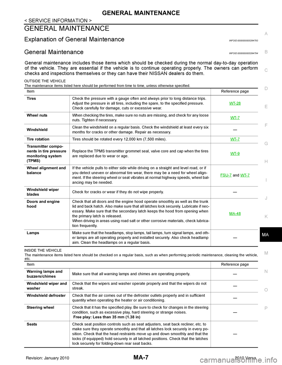
General maintenance includes those items which shoul d be checked during the normal day-to-day operation
of the vehicle. They are essential if the vehicle is to continue operating properly. The owners can perform
checks and inspections themselves or they can have their NISSAN dealers do them.
OUTSIDE THE VEHICLE
The maintenance items listed here should be performed from time to time, unless otherwise specified.
INSIDE THE VEHICLE The maintenance items listed here should be checked on a regular basis, such as when performing periodic maintenance, cleaning the vehicle,
etc.
Item Reference page
Tires Check the pressure with a gauge often and always prior to long distance trips.
Adjust the pressure in all tires, including the spare, to the specified pressure.
Check carefully for damage, cuts or excessive wear. WT-28
Wheel nuts
When checking the tires, make sure no nuts are missing, and check for any loose
nuts. Tighten if necessary. WT-7
WindshieldClean the windshield on a regular basis. Check the windshield at least every six
months for cracks or other damage. Repair as necessary.
—
Tire rotation Tires should be rotated every 12,000 km (7,500 miles). WT-7
Transmitter compo-
nents in tire pressure
monitoring system
(TPMS)Replace the TPMS transmitter grommet seal, valve core and cap when the tires
are replaced due to wear or age.
WT-9
Wheel alignment and
balanceIf the vehicle pulls to either side while driving on a straight and level road, or if
you detect uneven or abnormal tire wear, there may be a need for wheel align-
ment. If the steering wheel or seat vibrates at normal highway speeds, wheel bal-
ancing may be needed. FSU-7
and
WT-7
Windshield wiper
blades Check for cracks or wear if they do not wipe properly.
—
Doors and engine
hood Check that all doors and the engine hood operate smoothly as well as the trunk
lid and back hatch. Also make sure that all latches lock securely. Lubricate if nec-
essary. Make sure that the secondary latch keeps the hood from opening when
the primary latch is released.
When driving in areas using road salt or other corrosive materials, check lubrica-
tion frequently. MA-48
Lamps
Make sure that the headlamps, stop lamps, tail lamps, turn signal lamps, and oth-
er lamps are all operating properly and installed securely. Also check headlamp
aim. Clean the headlamps on a regular basis. —
Item
Reference page
Warning lamps and
buzzers/chimes Make sure that all warning lamps and chimes are operating properly.
—
Windshield wiper and
washer Check that the wipers and washer operate properly and that the wipers do not
streak.
—
Windshield defroster Check that the air comes out of the defroster outlets properly and in sufficient
quantity when operating the heater or air conditioning. —
Steering wheel Check that it has the specified play. Be sure to check for changes in the steering
condition, such as excessive play, hard steering or strange noises.
Free play: Less than 35 mm (1.38 in) —
Seats Check seat position controls such as seat adjusters, seat back recliner, etc. to
make sure they operate smoothly and that all latches lock securely in every po-
sition. Check that the head restraints move up and down smoothly and that the
locks (if equipped) hold securely in all latched positions. Check that the latches
lock securely for folding-down rear seat backs. —
Revision: January 20102010 Versa