2010 NISSAN TIIDA check oil
[x] Cancel search: check oilPage 331 of 3745
AT-314
< SERVICE INFORMATION >
REPAIR FOR COMPONENT PARTS
Low & Reverse Brake
INFOID:0000000005397444
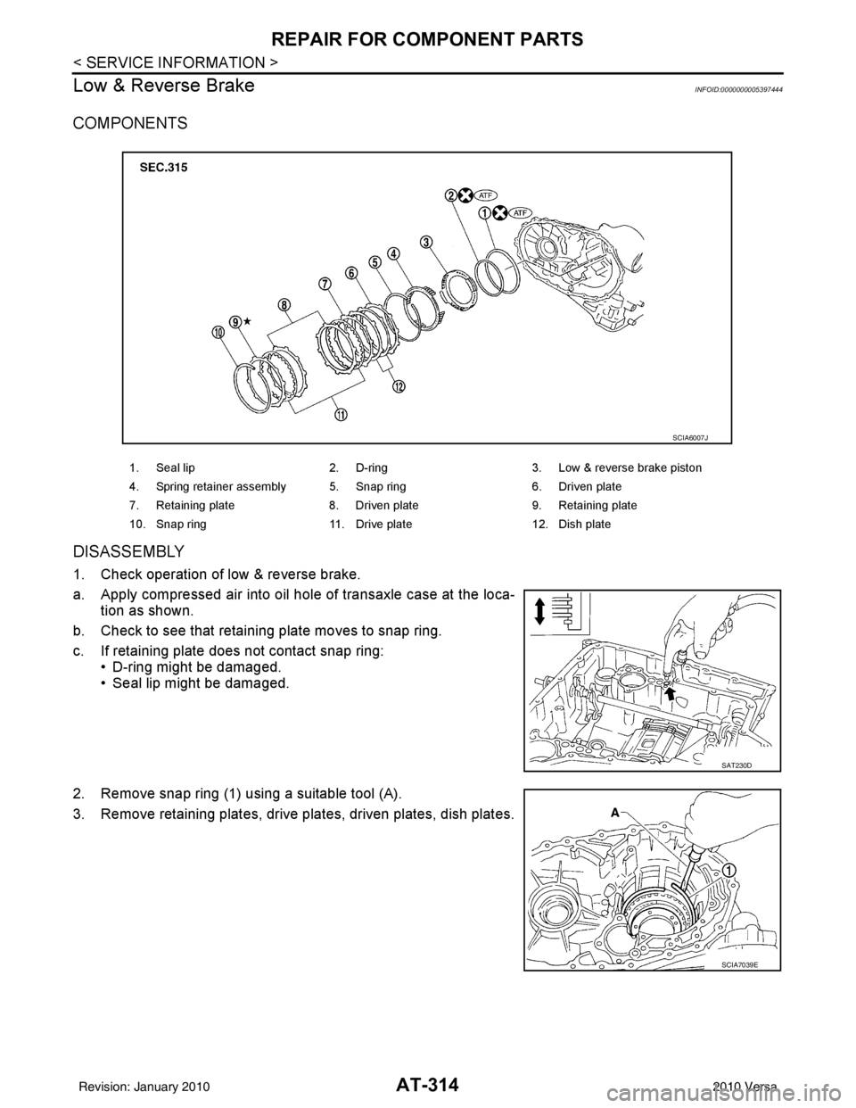
COMPONENTS
DISASSEMBLY
1. Check operation of low & reverse brake.
a. Apply compressed air into oil hole of transaxle case at the loca- tion as shown.
b. Check to see that retaining plate moves to snap ring.
c. If retaining plate does not contact snap ring: • D-ring might be damaged.
• Seal lip might be damaged.
2. Remove snap ring (1) using a suitable tool (A).
3. Remove retaining plates, drive plates, driven plates, dish plates.
1. Seal lip 2. D-ring 3. Low & reverse brake piston
4. Spring retainer assembly 5. Snap ring 6. Driven plate
7. Retaining plate 8. Driven plate 9. Retaining plate
10. Snap ring 11. Drive plate 12. Dish plate
SCIA6007J
SAT230D
SCIA7039E
Revision: January 20102010 Versa
Page 332 of 3745
REPAIR FOR COMPONENT PARTSAT-315
< SERVICE INFORMATION >
DE
F
G H
I
J
K L
M A
B
AT
N
O P
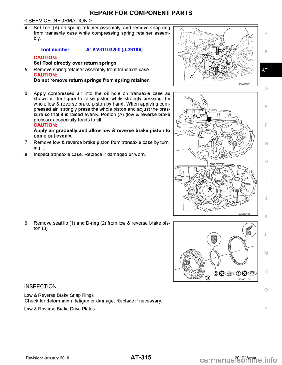
4. Set Tool (A) on spring retainer assembly, and remove snap ring from transaxle case while compressing spring retainer assem-
bly.
CAUTION:
Set Tool directly over return springs.
5. Remove spring retainer assembly from transaxle case. CAUTION:
Do not remove return springs from spring retainer.
6. Apply compressed air into the oil hole on transaxle case as shown in the figure to raise piston while strongly pressing the
whole low & reverse brake piston by hand. When applying com-
pressed air, strongly press the whole piston and adjust the pres-
sure so that it is raised evenly. Portion (A) (low & reverse brake
pressure) especially tends to tilt.
CAUTION:
Apply air gradually and allow low & reverse brake piston to
come out evenly.
7. Remove low & reverse brake piston from transaxle case by turn- ing it.
8. Inspect transaxle case. Replace if damaged or worn.
9. Remove seal lip (1) and D-ring (2) from low & reverse brake pis- ton (3).
INSPECTION
Low & Reverse Brake Snap Rings
Check for deformation, fatigue or damage. Replace if necessary.
Low & Reverse Brake Drive Plates
Tool number A: KV31103200 (J-39186)
SCIA7990E
SCIA6346J
SCIA6516J
Revision: January 20102010 Versa
Page 382 of 3745
ASSEMBLYAT-365
< SERVICE INFORMATION >
DE
F
G H
I
J
K L
M A
B
AT
N
O P
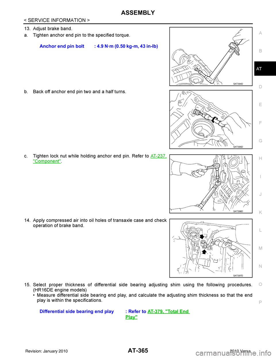
13. Adjust brake band.
a. Tighten anchor end pin to the specified torque.
b. Back off anchor end pin two and a half turns.
c. Tighten lock nut while holding anchor end pin. Refer to AT-237,
"Component".
14. Apply compressed air into oil holes of transaxle case and check operation of brake band.
15. Select proper thickness of differential side bear ing adjusting shim using the following procedures.
(HR16DE engine models)
• Measure differential side bearing end play, and calculat e the adjusting shim thickness so that the end
play is within the specifications. Anchor end pin bolt : 4.9 N·m (0.50 kg-m, 43 in-lb)
SAT394D
SAT395D
SAT396D
SAT397D
Differential side bearin
g end play : Refer to AT-379, "Total End
Play"
Revision: January 20102010 Versa
Page 418 of 3745
![NISSAN TIIDA 2010 Service Repair Manual AUDIOAV-21
< SERVICE INFORMATION > [AUDIO WITHOUT NAVIGATION]
C
D
E
F
G H
I
J
L
M A
B
AV
N
O P
NOTE:
Noise resulting from variations in field strength, such as fading noise and multi-path noise, or e](/manual-img/5/57397/w960_57397-417.png "NISSAN TIIDA 2010 Service Repair Manual AUDIOAV-21
< SERVICE INFORMATION > [AUDIO WITHOUT NAVIGATION]
C
D
E
F
G H
I
J
L
M A
B
AV
N
O P
NOTE:
Noise resulting from variations in field strength, such as fading noise and multi-path noise, or e")
AUDIOAV-21
< SERVICE INFORMATION > [AUDIO WITHOUT NAVIGATION]
C
D
E
F
G H
I
J
L
M A
B
AV
N
O P
NOTE:
Noise resulting from variations in field strength, such as fading noise and multi-path noise, or external noise
from trains and other sources. It is not a malfunction.
• Fading noise: This noise occurs because of variations in the field strength in a narrow range due to moun-
tains or buildings blocking the signal.
• Multi-path noise: This noise results from the waves sent directly from the broadcast station arriving at the antenna at a different time from the waves t hat reflect off of mountains or buildings.
Noise InspectionINFOID:0000000005395318
The vehicle itself can be a source of noise if noise prevention parts or electrical equipment is malfunctioning.
Check if noise is caused and/or changed by engine speed, ignition switch turned to each position, and opera-
tion of each piece of electrical equipment, and determine the cause.
NOTE:
The source of the noise can be found easily by listening to the noise while removing the fuses of electrical
components, one by one.
TYPE OF NOISE AND POSSIBLE CAUSE
No sound can be heard from one or several speakers. • Open or short in audio signal circuit between audio unit and front
speaker. Refer to AV- 2 4 , "
Sound Is Not Heard from Front Door
Speaker (Base System)" or AV- 2 6 , "Sound Is Not Heard from
Front Door Speaker or Tweeter (Premium System)" .
• Front speaker. Refer to AV- 2 4 , "
Sound Is Not Heard from Front
Door Speaker (Base System)" or AV- 2 6 , "Sound Is Not Heard
from Front Door Speaker or Tweeter (Premium System)" .
• Open or short in audio signal circuit between audio unit and rear
speaker. Refer to AV- 2 5 , "
Sound Is Not Heard from Rear Door
Speaker (Base System)" or AV- 2 7 , "Sound Is Not Heard from
Rear Door Speaker (Premium System)" .
• Rear speaker. Refer to AV- 2 5 , "
Sound Is Not Heard from Rear
Door Speaker (Base System)" or AV- 2 7 , "Sound Is Not Heard
from Rear Door Speaker (Premium System)" .
• Tweeter (mid level and premium system) AV- 2 6 , "
Sound Is Not
Heard from Front Door Speaker or Tweeter (Premium System)"
or AV- 2 7 , "
Sound Is Not Heard from Rear Door Speaker (Premi-
um System)" .
• Audio unit. Refer to AV- 2 9 , "
Removal and Installation" .
No sound can be heard from radio or noise is heard. • Antenna feeder. Refer to
AV- 3 3
.
• Antenna. Refer to AV- 3 3
.
• Audio unit. Refer to AV- 2 9 , "
Removal and Installation" .
Symptom
Check item
Occurrence condition Possible cause
Occurs only when engine is ON. A continuous growling noise occurs. The speed of
the noise varies with changes in the engine speed.
Ignition components
A whistling noise occurs while the engine speed is
high. A booming noise occurs while the engine is
running and the lighting switch is ON. Generator
Noise only occurs when various
electrical components are oper-
ating. A cracking or snapping sound occurs with the op-
eration of various switches.
Relay malfunction, radio malfunction
The noise occurs when various motors are operat-
ing. • Motor case ground
•Motor
The noise occurs constantly, not just under certain conditions. • Rear defogger coil malfunction
• Open circuit in printed heater
A cracking or snapping sound occurs while the vehicle is being driven, especially when
it is vibrating excessively. • Ground wire of body parts.
• Ground due to improper part installation
• Wiring connections or a short circuit
Revision: January 20102010 Versa
Page 507 of 3745

BCS-18
< SERVICE INFORMATION >
BCM (BODY CONTROL MODULE)
WORK SUPPORT
Display Item List
CAN Communication Inspection Using CONSULT-III (Self-Diagnosis)INFOID:0000000005395110
1.SELF-DIAGNOSTIC RESULT CHECK
1. Connect CONSULT–III and select “BCM” on “SELECT SYSTEM” screen.
2. Select “BCM” on “SELECT TEST ITEM” screen, and select “SELF-DIAG RESULTS”.
3. Check display content in self-diagnostic results.
Warning chime BUZZER ××
Room lamp timer INT LAMP ×× ×
Remote keyless entry
system MULTI REMOTE
ENT
××
×
Headlamp HEAD LAMP×× ×
Wiper WIPER×× ×
Turn signal lamp
Hazard lamp FLASHER
××
Blower fan switch sig-
nal
Air conditioner switch
signal AIR CONDITION-
ER
××
Intelligent Key INTELLIGENT
KEY
×
Combination switch COMB SW ×
NVIS (NATS) IMMU ××
Interior lamp battery
saver BATTERY SAV-
ER
××
×
Back door/Trunk TRUNK ××
Theft alarm THEFT ALARM×× ×
Retained accessory
power control RETAINED PWR
×× ×
Oil pressure swit ch SIGNAL BUFFER ××
Low tire pressure moni-
tor AIR PRESSURE
MONITOR
××
× ×
Panic alarm PANIC ALARM ×
System and item
CONSULT-III dis-
play Diagnostic test mode (Inspection by part)
WORK
SUPPORT SELF
−
DIAG RE-
SULTS CAN DIAG
SUPPORT
MNTR DATA
MONITOR ECU
PA R T
NUMBER AC-
TIVE
TEST CON-
FIGU-
RATION
Item Description
RESET SETTING VALUE Return a value set with WORK SUPPORT of each system to a default value in factory shipment.
CONSULT-III display code Diagnosis item
U1000 INITIAL DIAG
TRANSMIT DIAG ECM
IPDM E/R
METER/M&A I-KEY
Revision: January 20102010 Versa
Page 851 of 3745
PRECAUTIONSBR-3
< SERVICE INFORMATION >
C
DE
G H
I
J
K L
M A
B
BR
N
O P
5. When the repair work is completed, return the ignition switch to the ″LOCK ″ position before connecting
the battery cables. (At this time, the steering lock mechanism will engage.)
6. Perform a self-diagnosis check of al l control units using CONSULT-III.
Precaution for Brake SystemINFOID:0000000005396974
• Refill using recommended brake fluid. Refer to MA-14.
• Never reuse drained brake fluid.
• Be careful not to splash brake fluid on painted surface of body. If brake fluid is splashed on painted surfaces of body immediately wipe it off with cloth and then wash it away with water.
• To clean or wash all parts of master cylinder, disc brake caliper and wheel cylinder, use new brake fluid.
• Never use mineral oils such as gasoline or kerosene. They will ruin rubber parts of the hydraulic system.
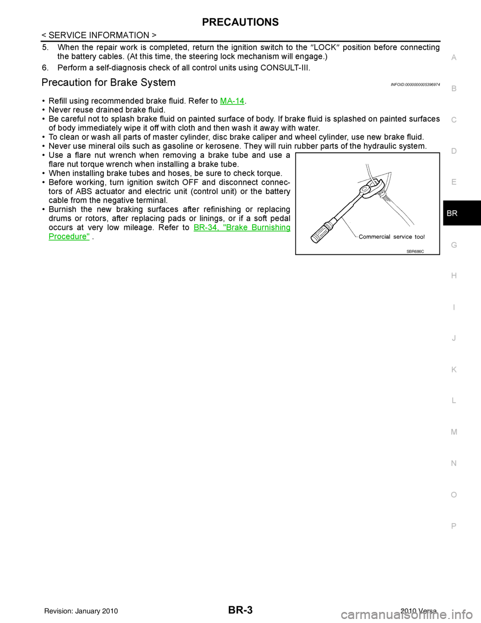
• Use a flare nut wrench when removing a brake tube and use a flare nut torque wrench when installing a brake tube.
• When installing brake tubes and hoses, be sure to check torque.
• Before working, turn igniti on switch OFF and disconnect connec-
tors of ABS actuator and electric unit (control unit) or the battery
cable from the negative terminal.
• Burnish the new braking surfaces after refinishing or replacing drums or rotors, after replacing p ads or linings, or if a soft pedal
occurs at very low mileage. Refer to BR-34, "
Brake Burnishing
Procedure" .
SBR686C
Revision: January 20102010 Versa
Page 864 of 3745
BR-16
< SERVICE INFORMATION >
BRAKE MASTER CYLINDER
INSTALLATION
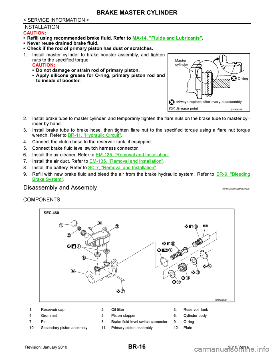
CAUTION:
• Refill using recommended brake fluid. Refer to MA-14, "
Fluids and Lubricants".
• Never reuse drained brake fluid.
• Check if the rod of primary piston has dust or scratches.
1. Install master cylinder to brake booster assembly, and tighten nuts to the specified torque.
CAUTION:
• Do not damage or strain rod of primary piston.
• Apply silicone grease for O-ring, primary piston rod andto inside of booster.
2. Install brake tube to master cylinder, and temporarily tighten the flare nuts on the brake tube to master cyl- inder by hand.
3. Install brake tube to brake hose, then tighten flare nut to the specified torque using a flare nut torque
wrench. Refer to BR-11, "
Hydraulic Circuit".
4. Connect the clutch hose to the reservoir tank, if equipped.
5. Connect brake fluid level switch harness connector.
6. Install the air cleaner. Refer to EM-135, "
Removal and Installation".
7. Install the air duct. Refer to EM-135, "
Removal and Installation".
8. Install the battery. Refer to SC-7, "
Removal and Installation".
9. Refill with new brake fluid and bleed the air from the brake hydraulic system. Refer toBR-9, "
Bleeding
Brake System".
Disassembly and AssemblyINFOID:0000000005396991
COMPONENTS
SFIA2614E
1. Reservoir cap2. Oil filter 3. Reservoir tank
4. Grommet 5. Piston stopper 6. Cylinder body
7. Pin 8. Brake fluid level switch connector 9. O-ring
10. Secondary piston assembly 11. Primary piston assembly 12. Plate
SFIA3094E
Revision: January 20102010 Versa
Page 866 of 3745
BR-18
< SERVICE INFORMATION >
BRAKE MASTER CYLINDER
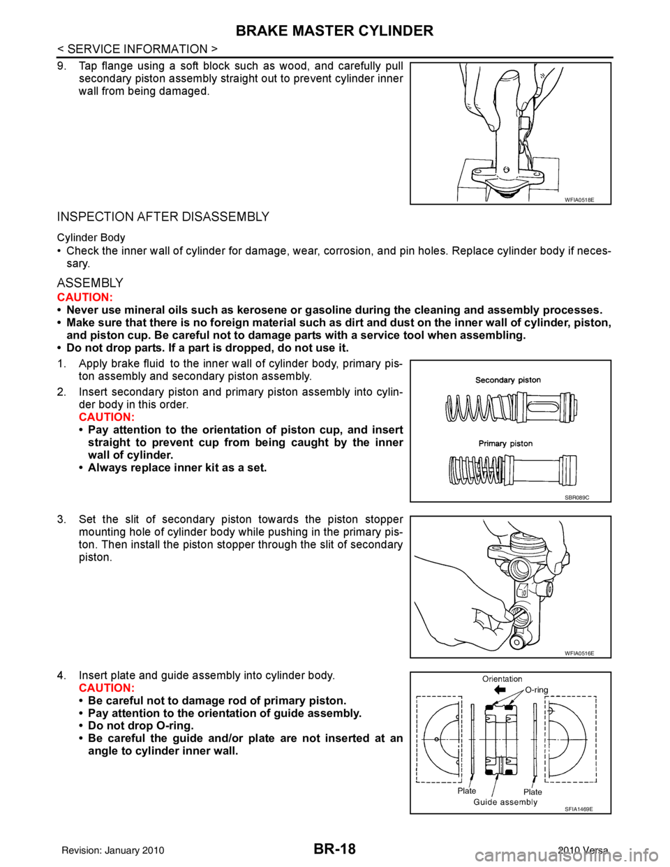
9. Tap flange using a soft block such as wood, and carefully pullsecondary piston assembly straight out to prevent cylinder inner
wall from being damaged.
INSPECTION AFTER DISASSEMBLY
Cylinder Body
• Check the inner wall of cylinder for damage, wear, corrosion, and pin holes. Replace cylinder body if neces-sary.
ASSEMBLY
CAUTION:
• Never use mineral oils such as kerosene or g asoline during the cleaning and assembly processes.
• Make sure that there is no foreign material such as dirt and dust on the inner wall of cylinder, piston,
and piston cup. Be careful not to damage parts with a service tool when assembling.
• Do not drop parts. If a part is dropped, do not use it.
1. Apply brake fluid to the inner wall of cylinder body, primary pis- ton assembly and secondary piston assembly.
2. Insert secondary piston and primary piston assembly into cylin- der body in this order.
CAUTION:
• Pay attention to the orientation of piston cup, and insert
straight to prevent cup from being caught by the inner
wall of cylinder.
• Always replace inner kit as a set.
3. Set the slit of secondary piston towards the piston stopper mounting hole of cylinder body while pushing in the primary pis-
ton. Then install the piston stopper through the slit of secondary
piston.
4. Insert plate and guide assembly into cylinder body. CAUTION:
• Be careful not to damage rod of primary piston.
• Pay attention to the orientation of guide assembly.
• Do not drop O-ring.
• Be careful the guide and/or plate are not inserted at an
angle to cylinder inner wall.
WFIA0518E
SBR089C
WFIA0516E
SFIA1469E
Revision: January 20102010 Versa