Page 242 of 3745
ON-VEHICLE SERVICEAT-225
< SERVICE INFORMATION >
DE
F
G H
I
J
K L
M A
B
AT
N
O P
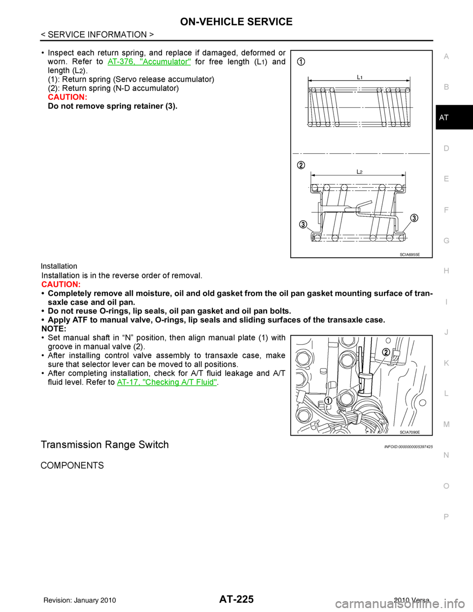
• Inspect each return spring, and replace if damaged, deformed or worn. Refer to AT-376, "
Accumulator" for free length (L1) and
length (L
2).
(1): Return spring (Servo release accumulator)
(2): Return spring (N-D accumulator)
CAUTION:
Do not remove spring retainer (3).
Installation
Installation is in the reverse order of removal.
CAUTION:
• Completely remove all moisture, oil and old gasket from the oil pan gasket mounting surface of tran-
saxle case and oil pan.
• Do not reuse O-rings, lip seals, oil pan gasket and oil pan bolts.
• Apply ATF to manual valve, O-rings, lip seals and sliding surfaces of the transaxle case.
NOTE:
• Set manual shaft in “N” position, then align manual plate (1) with groove in manual valve (2).
• After installing control valve assembly to transaxle case, make sure that selector lever can be moved to all positions.
• After completing installation, check for A/T fluid leakage and A/T fluid level. Refer to AT-17, "
Checking A/T Fluid".
Transmission Range SwitchINFOID:0000000005397425
COMPONENTS
SCIA6955E
SCIA7090E
Revision: January 20102010 Versa
Page 248 of 3745
ON-VEHICLE SERVICEAT-231
< SERVICE INFORMATION >
DE
F
G H
I
J
K L
M A
B
AT
N
O P
• After installing differential side oil seal, check A/T fluid leakage and A/T fluid level. Refer to AT-17, "Checking
A/T Fluid".
Revision: January 20102010 Versa
Page 252 of 3745
TRANSAXLE ASSEMBLYAT-235
< SERVICE INFORMATION >
DE
F
G H
I
J
K L
M A
B
AT
N
O P
• When replacing an engine or transmission you must make sure any dowels are installed correctly during re-assembly.
• Improper alignment caused by missing dowels may cause vibration, oil leaks or breakage of drive
train components.
• Do not reuse O-rings and copper washers. Refer to "COMPONENTS".
• When turning crankshaft, turn it clockwise as viewed from the front of the engine.
• When tightening the bolts for th e torque converter while securing the crankshaft pulley bolt, be sure
to confirm the tightening torque of the crankshaft pulley bolt. Refer to EM-156
.
• After converter is installed to drive plate, ro tate crankshaft several turns to check that transaxle
rotates freely without binding.
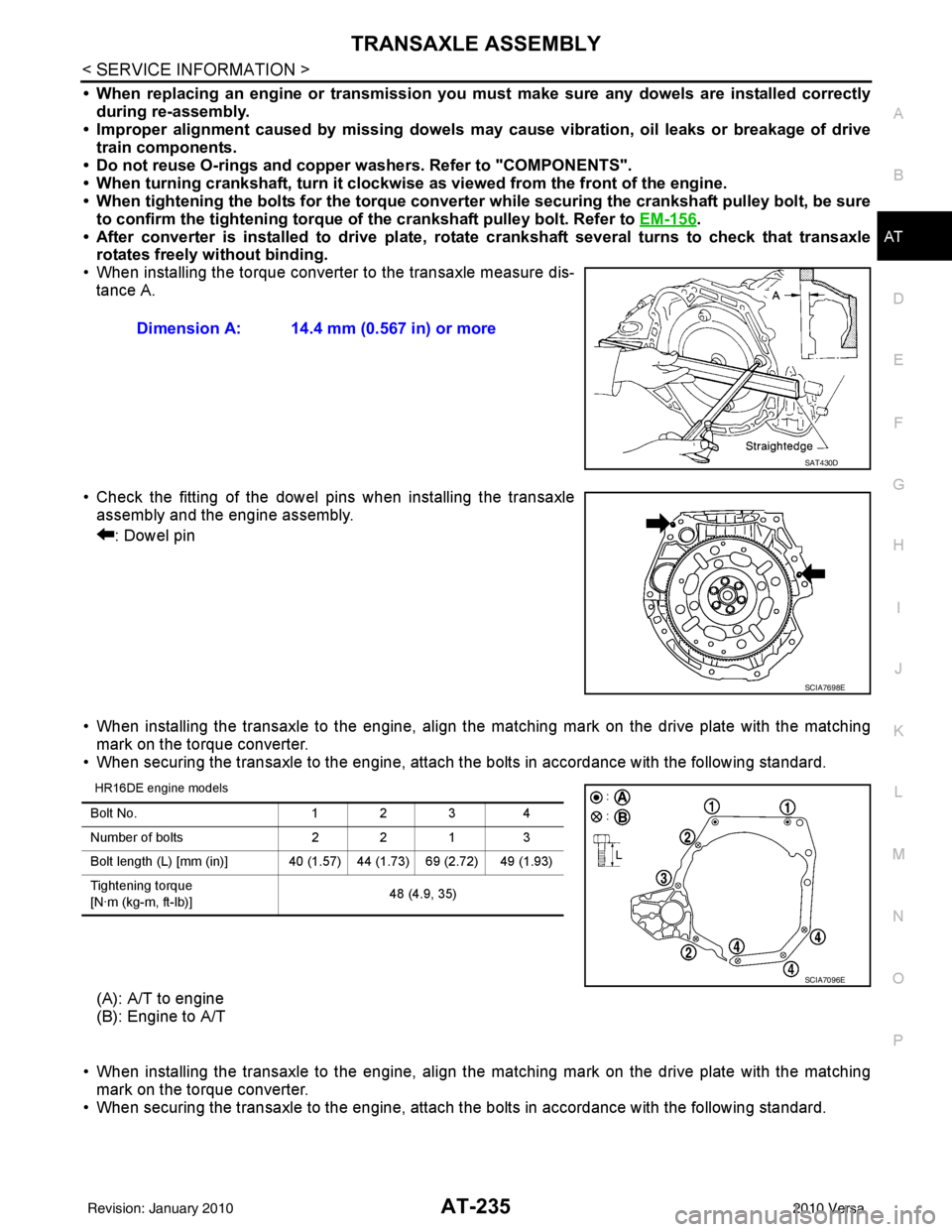
• When installing the torque converter to the transaxle measure dis- tance A.
• Check the fitting of the dowel pins when installing the transaxle assembly and the engine assembly.
: Dowel pin
• When installing the transaxle to the engine, align the matching mark on the drive plate with the matching mark on the torque converter.
• When securing the transaxle to the engine, attach the bolts in accordance with the following standard.
HR16DE engine models
(A): A/T to engine
(B): Engine to A/T
• When installing the transaxle to the engine, align the matching mark on the drive plate with the matching mark on the torque converter.
• When securing the transaxle to the engine, attach the bolts in accordance with the following standard. Dimension A: 14.4 mm (0.567 in) or more
SAT430D
SCIA7698E
Bolt No.
1 2 34
Number of bolts 2 2 13
Bolt length (L) [mm (in)] 40 (1.5 7) 44 (1.73) 69 (2.72) 49 (1.93)
Tightening torque
[N·m (kg-m, ft-lb)] 48 (4.9, 35)
SCIA7096E
Revision: January 20102010 Versa
Page 276 of 3745
DISASSEMBLYAT-259
< SERVICE INFORMATION >
DE
F
G H
I
J
K L
M A
B
AT
N
O P
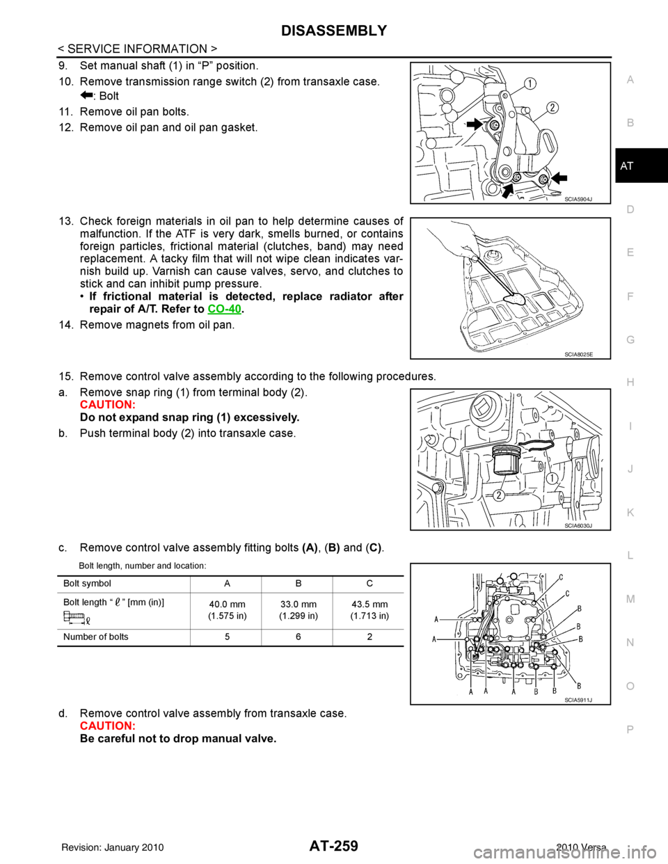
9. Set manual shaft (1) in “P” position.
10. Remove transmission range switch (2) from transaxle case. : Bolt
11. Remove oil pan bolts.
12. Remove oil pan and oil pan gasket.
13. Check foreign materials in oil pan to help determine causes of malfunction. If the ATF is very dark, smells burned, or contains
foreign particles, frictional material (clutches, band) may need
replacement. A tacky film that will not wipe clean indicates var-
nish build up. Varnish can cause valves, servo, and clutches to
stick and can inhibit pump pressure.
•If frictional material is detected, replace radiator after
repair of A/T. Refer to CO-40
.
14. Remove magnets from oil pan.
15. Remove control valve assembly according to the following procedures.
a. Remove snap ring (1) from terminal body (2). CAUTION:
Do not expand snap ring (1) excessively.
b. Push terminal body (2) into transaxle case.
c. Remove control valve assembly fitting bolts (A), (B) and ( C).
Bolt length, number and location:
d. Remove control valve assembly from transaxle case.
CAUTION:
Be careful not to drop manual valve.
SCIA5904J
SCIA8025E
SCIA6030J
Bolt symbol ABC
Bolt length “ ” [mm (in)] 40.0 mm
(1.575 in) 33.0 mm
(1.299 in) 43.5 mm
(1.713 in)
Number of bolts 562
SCIA5911J
Revision: January 20102010 Versa
Page 293 of 3745
AT-276
< SERVICE INFORMATION >
REPAIR FOR COMPONENT PARTS
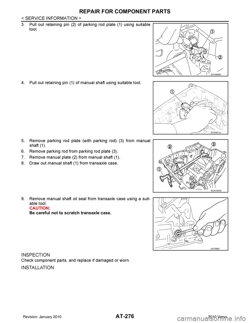
3. Pull out retaining pin (2) of parking rod plate (1) using suitabletool.
4. Pull out retaining pin (1) of manual shaft using suitable tool.
5. Remove parking rod plate (with parking rod) (3) from manual shaft (1).
6. Remove parking rod from parking rod plate (3).
7. Remove manual plate (2) from manual shaft (1).
8. Draw out manual shaft (1) from transaxle case.
9. Remove manual shaft oil seal from transaxle case using a suit- able tool.
CAUTION:
Be careful not to scratch transaxle case.
INSPECTION
Check component parts, and replace if damaged or worn.
INSTALLATION
SCIA5806J
SCIA6514J
SCIA7005E
SAT080D
Revision: January 20102010 Versa
Page 296 of 3745
REPAIR FOR COMPONENT PARTSAT-279
< SERVICE INFORMATION >
DE
F
G H
I
J
K L
M A
B
AT
N
O P
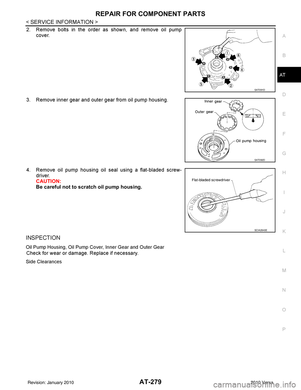
2. Remove bolts in the order as shown, and remove oil pump cover.
3. Remove inner gear and outer gear from oil pump housing.
4. Remove oil pump housing oil seal using a flat-bladed screw- driver.
CAUTION:
Be careful not to scratch oil pump housing.
INSPECTION
Oil Pump Housing, Oil Pump Co ver, Inner Gear and Outer Gear
Check for wear or damage. Replace if necessary.
Side Clearances
SAT091D
SAT092D
SCIA2840E
Revision: January 20102010 Versa
Page 299 of 3745
AT-282
< SERVICE INFORMATION >
REPAIR FOR COMPONENT PARTS
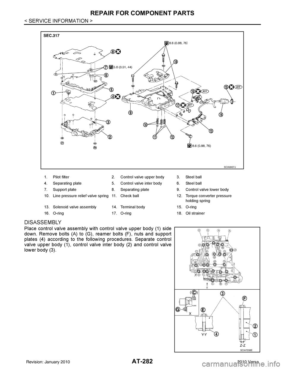
DISASSEMBLY
Place control valve assembly with control valve upper body (1) side
down. Remove bolts (A) to (G), reamer bolts (F), nuts and support
plates (4) according to the following procedures. Separate control
valve upper body (1), control valve inter body (2) and control valve
lower body (3).
1. Pilot filter2. Control valve upper body 3. Steel ball
4. Separating plate 5. Control valve inter body 6. Steel ball
7. Support plate 8. Separating plate9. Control valve lower body
10. Line pressure relief valve spring 11. Check ball 12. Torque converter pressure
holding spring
13. Solenoid valve assembly 14. Terminal body 15. O-ring
16. O-ring 17. O-ring18. Oil strainer
SCIA8407J
SCIA7058E
Revision: January 20102010 Versa
Page 302 of 3745
REPAIR FOR COMPONENT PARTSAT-285
< SERVICE INFORMATION >
DE
F
G H
I
J
K L
M A
B
AT
N
O P
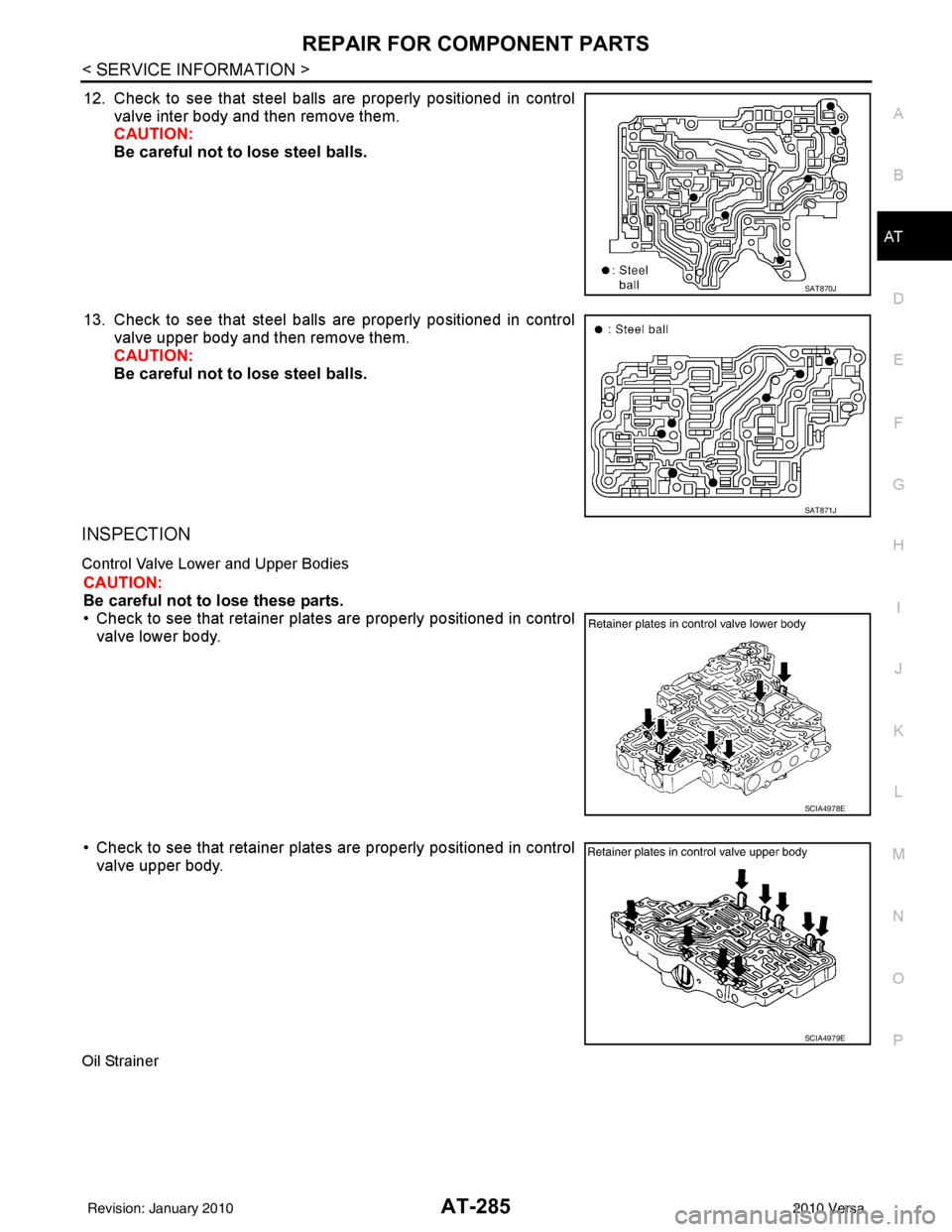
12. Check to see that steel balls are properly positioned in control
valve inter body and then remove them.
CAUTION:
Be careful not to lose steel balls.
13. Check to see that steel balls are properly positioned in control
valve upper body and then remove them.
CAUTION:
Be careful not to lose steel balls.
INSPECTION
Control Valve Lower and Upper Bodies
CAUTION:
Be careful not to lose these parts.
• Check to see that retainer plates are properly positioned in control
valve lower body.
• Check to see that retainer plates are properly positioned in control
valve upper body.
Oil Strainer
SAT870J
SAT871J
SCIA4978E
SCIA4979E
Revision: January 20102010 Versa