2010 NISSAN TIIDA ECO mode
[x] Cancel search: ECO modePage 601 of 3745
BL-92
< SERVICE INFORMATION >
INTELLIGENT KEY SYSTEM
The headlamp flashes and the horn sounds intermittently.
The alarm automatically turns off:
• After 25 seconds
• When Intelligent Key unit receives any signal from remote controller of Intelligent Key
• When door request switch is pressed (Intelligent Key is outside vehicle)
Panic alarm function's press and holding time value can be changed in “PANIC ALARM DELAY” mode in
“WORK SUPPORT”. Refer to BL-117, "
CONSULT-III Application Item".
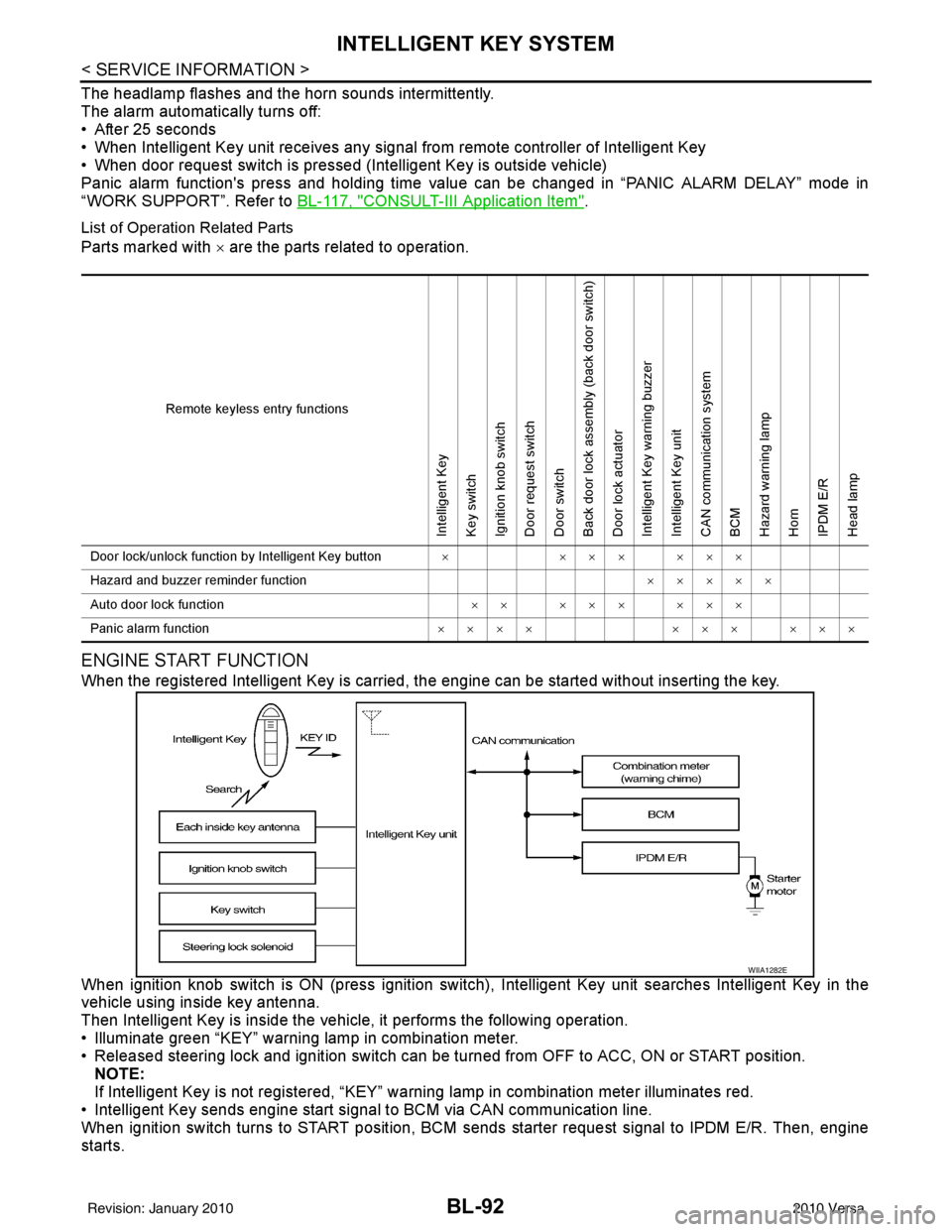
List of Operation Related Parts
Parts marked with × are the parts related to operation.
ENGINE START FUNCTION
When the registered Intelligent Key is carried, the engine can be started without inserting the key.
When ignition knob switch is ON (press ignition switch ), Intelligent Key unit searches Intelligent Key in the
vehicle using inside key antenna.
Then Intelligent Key is inside the vehicle, it performs the following operation.
• Illuminate green “KEY” warning lamp in combination meter.
• Released steering lock and ignition switch can be turned from OFF to ACC, ON or START position.
NOTE:
If Intelligent Key is not registered, “KEY” warning lamp in combination meter illuminates red.
• Intelligent Key sends engine start signal to BCM via CAN communication line.
When ignition switch turns to START position, BCM sends starter request signal to IPDM E/R. Then, engine
starts.
Remote keyless entry functions
Intelligent Key
Key switch
Ignition knob switch
Door request switch
Door switch
Back door lock assembly (back door switch)
Door lock actuator
Intelligent Key warning buzzer
Intelligent Key unit
CAN communication system
BCM
Hazard warning lamp
Horn
IPDM E/R
Head lamp
Door lock/unlock function by Intelligent Key button × ××× ×××
Hazard and buzzer reminder function ×××××
Auto door lock function ×× ××× ×××
Panic alarm function ×××× ××× ×××
WIIA1282E
Revision: January 20102010 Versa
Page 628 of 3745

INTELLIGENT KEY SYSTEMBL-119
< SERVICE INFORMATION >
C
DE
F
G H
J
K L
M A
B
BL
N
O P
Trouble Diagnosis Symptom ChartINFOID:0000000005396611
KEY WARNING LAMP (GREEN) ILLUMINATES
NOTE:
• Before performing the diagnosis in the following table, check “Trouble Diagnosis Procedure”. Refer to BL-
115, "Trouble Diagnosis Procedure".
• Make sure that vehicle is under the condition shown in “Conditions of vehicle” before starting diagnosis, and
check each symptom.
• If the following “symptoms” are detected, check syst ems shown in the “Diagnoses/service procedure” col-
umn in this order.
LOW BAT OF KEY FOB WARN Intelligent Key low battery warning mode can be changed to operate (ON) or not operate (OFF)
with this mode. The operation mode will be changed when “CHANGE
SETT” on CONSULT-III
screen is touched.
ANSWER BACK FUNCTION Buzzer reminder function mode by Intelligent button can be changed to operate (ON) or not oper-
ate (OFF) with this mode. The operation mode will be changed when “CHANGE SETT” on CON-
SULT-III screen is touched.
SELECTIVE UNLOCK FUNC-
TION Selective unlock function mode can be changed to operate (ON) or not operate (OFF) with this
mode. The operation mode will be changed when “CHANGE SETT” on CONSULT-III screen is
touched.
ANTI KEY LOCK IN FUNCTION Key reminder function mode can be changed to operate (ON) or not operate (OFF) with this mode.
The operation mode will be changed when “CHANGE SETT” on CONSULT-III screen is touched.
HORN WITH KEYLESS LOCK Horn reminder function mode by Intelligent Key remote control button can be changed to operate
(ON) or not operate (OFF) with this mode. The operation mode will be changed when “CHANGE
SETT” on CONSULT-III screen is touched.
HAZARD ANSWER BACK Hazard reminder function mode can be selected from the following with this mode. The operation
mode will be changed when “CHANGE SE
TT” on CONSULT-III screen is touched.
• LOCK ONLY: Door lock operation only
• UNLOCK ONLY: Door unlock operation only
• LOCK/UNLOCK: Lock/Unlock operation
• OFF: Non-operation
ANSWER BACK WITH I-KEY
LOCK Buzzer reminder function (lock operation) mode by door request switch (driver side, passenger
side and back door side) can be selected from the following with this mode. The operation mode
will be changed when “
CHANGE SETT” on CONSULT- III screen is touched.
• BUZZER: Sound buzzer
• OFF: Non-operation
ANSWER BACK WITH I-KEY UN-
LOCK Buzzer reminder function (unlock operation) mode by door request switch can be changed to op-
erate (ON) or not operate (OFF) with this mode.
AUTO RELOCK TIMER Auto door lock timer mode can select the following with this mode.
• 1 minute
• OFF: Non-operation
PANIC ALARM DELAY Panic alarm button's pressing time on Intelligent Key remote control button can be selected from
the following with this mode. The operation mode will be changed when “CHANGE SETT” on
CONSULT-III screen is touched.
• 0.5 second
• 1.5 second
• OFF: Non-operation
P/W DOWN DELAY Unlock button's pressing time on Intelligent Key remote control button can be selected from the
following with this mode. The operation mode will be changed when “CHANGE SETT” on CON-
SULT-III screen is touched.
• 3 seconds
• 5 seconds
• OFF: Non-operation
ENGINE START BY I-KEY Engine start function mode can be changed to operate (ON) or not operate (OFF) with this mode.
The operation mode will be changed when “CHANGE SETT” on CONSULT-III screen is touched.
LOCK/UNLOCK BY I-KEY Door lock/unlock function by door request switch (driver side, passenger side and back door side)
mode can be changed to operate (ON) or not operate (OFF) with this mode. The operation mode
will be changed when “
CHANGE SETT” on CONSULT- III screen is touched.
Monitor item
Description
Revision: January 20102010 Versa
Page 663 of 3745
BL-154
< SERVICE INFORMATION >
INTELLIGENT KEY SYSTEM
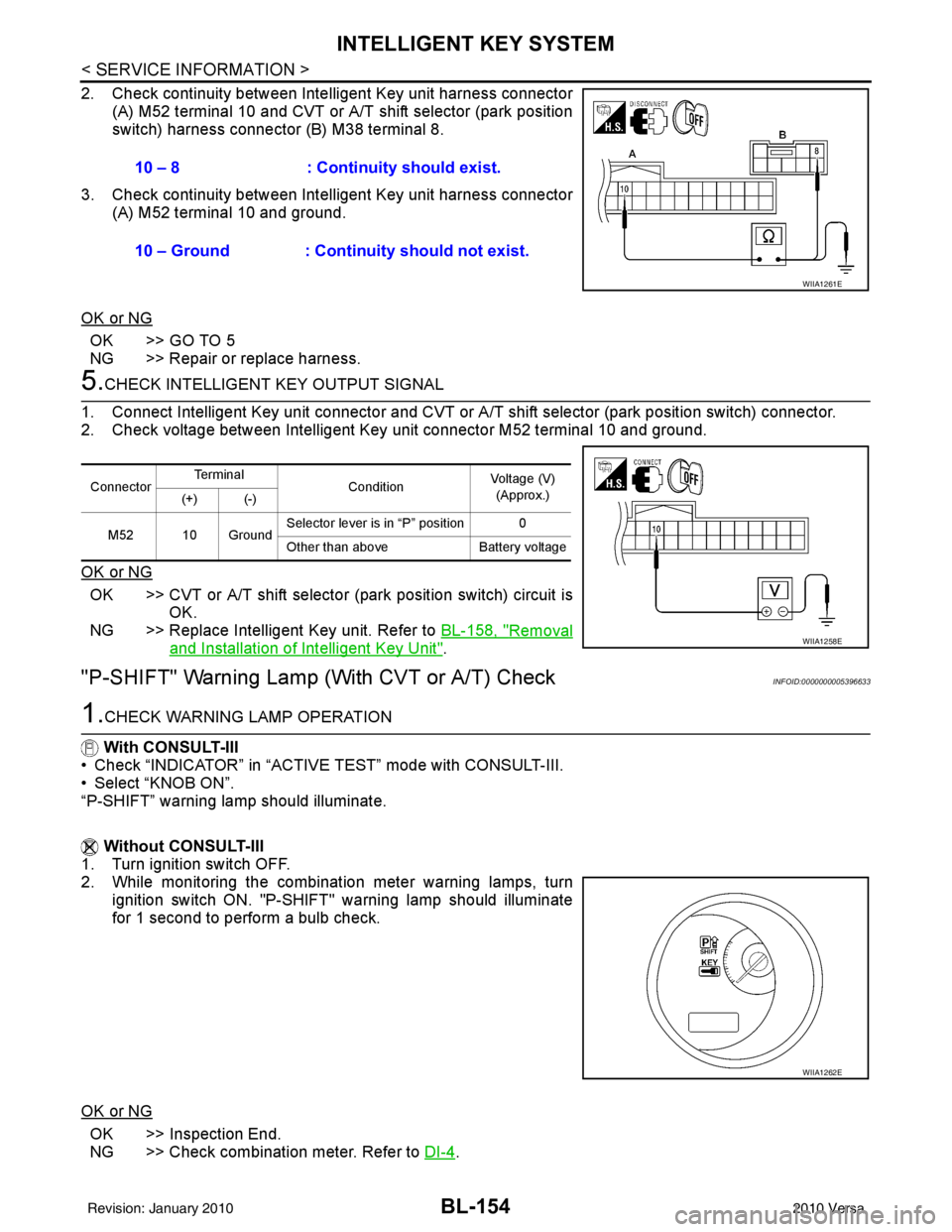
2. Check continuity between Intelligent Key unit harness connector
(A) M52 terminal 10 and CVT or A/T shift selector (park position
switch) harness connector (B) M38 terminal 8.
3. Check continuity between Inte lligent Key unit harness connector
(A) M52 terminal 10 and ground.
OK or NG
OK >> GO TO 5
NG >> Repair or replace harness.
5.CHECK INTELLIGENT KEY OUTPUT SIGNAL
1. Connect Intelligent Key unit connector and CVT or A/T shift selector (park position switch) connector.
2. Check voltage between Intelligent Key unit connector M52 terminal 10 and ground.
OK or NG
OK >> CVT or A/T shift selector (park position switch) circuit is
OK.
NG >> Replace Intelligent Key unit. Refer to BL-158, "
Removal
and Installation of Intelligent Key Unit".
"P-SHIFT" Warning Lamp (With CVT or A/T) CheckINFOID:0000000005396633
1.CHECK WARNING LAMP OPERATION
With CONSULT-III
• Check “INDICATOR” in “ACTIVE TEST” mode with CONSULT-III.
• Select “KNOB ON”.
“P-SHIFT” warning lamp should illuminate.
Without CONSULT-III
1. Turn ignition switch OFF.
2. While monitoring the combination meter warning lamps, turn
ignition switch ON. "P-SHIFT" warning lamp should illuminate
for 1 second to perform a bulb check.
OK or NG
OK >> Inspection End.
NG >> Check combination meter. Refer to DI-4
.
10 – 8 : Continuity should exist.
10 – Ground : Continuity should not exist.
WIIA1261E
Connector
Te r m i n a l
ConditionVoltage (V)
(Approx.)
(+) (-)
M52 10 Ground Selector lever is in “P” position 0
Other than above
Battery voltage
WIIA1258E
WIIA1262E
Revision: January 20102010 Versa
Page 664 of 3745
INTELLIGENT KEY SYSTEMBL-155
< SERVICE INFORMATION >
C
DE
F
G H
J
K L
M A
B
BL
N
O P
"LOCK" Warning Lamp (With M/T) CheckINFOID:0000000005396634
1.CHECK WARNING LAMP OPERATION
With CONSULT-III
• Check “INDICATOR” in “ACTIVE TEST” mode with CONSULT-III.
• Select “KNOB ON”.
“LOCK” warning lamp should illuminate.
Without CONSULT-III
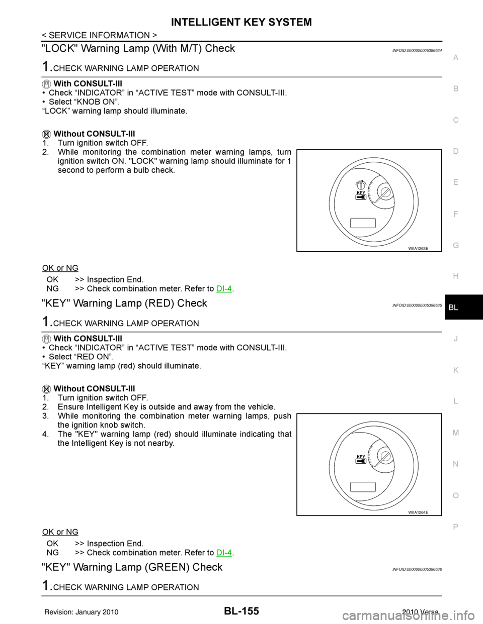
1. Turn ignition switch OFF.
2. While monitoring the combination meter warning lamps, turn
ignition switch ON. "LOCK" warning lamp should illuminate for 1
second to perform a bulb check.
OK or NG
OK >> Inspection End.
NG >> Check combination meter. Refer to DI-4
.
"KEY" Warning Lamp (RED) CheckINFOID:0000000005396635
1.CHECK WARNING LAMP OPERATION
With CONSULT-III
• Check “INDICATOR” in “ACTIVE TEST” mode with CONSULT-III.
• Select “RED ON”.
“KEY” warning lamp (red) should illuminate.
Without CONSULT-III
1. Turn ignition switch OFF.
2. Ensure Intelligent Key is outside and away from the vehicle.
3. While monitoring the combination meter warning lamps, push the ignition knob switch.
4. The "KEY" warning lamp (red) should illuminate indicating that the Intelligent Key is not nearby.
OK or NG
OK >> Inspection End.
NG >> Check combination meter. Refer to DI-4
.
"KEY" Warning Lamp (GREEN) CheckINFOID:0000000005396636
1.CHECK WARNING LAMP OPERATION
WIIA1263E
WIIA1264E
Revision: January 20102010 Versa
Page 743 of 3745

BL-234
< SERVICE INFORMATION >
VEHICLE SECURITY (THEFT WARNING) SYSTEM
Work Support
Data Monitor
* : With remote keyless entry system
** : With Intelligent Key system
Active Test
Test Item Description
SECURITY ALARM SET This mode can confirm and ch ange security alarm ON-OFF setting.
THEFT ALM TRG The switch which triggered vehicle security alarm is recorded. This mode is able to confirm and
erase the record of vehicle security alarm. The trigger data can be erased by touching “CLEAR” on
CONSULT-III screen.
Monitored Item
Description
IGN ON SW Indicates [ON/OFF] condition of ignition switch.
ACC ON SW Indicates [ON/OFF] condition of ignition switch in ACC position.
KEYLESS LOCK* Indicates [ON/OFF] condition of lock signal from keyfob.
KEYLESS UNLOCK* Indicates [ON/OFF] condition of unlock signal from keyfob.
I-KEY LOCK** Indicates [ON/OFF] condition of lock signal from keyfob.
I-KEY UNLOCK** Indicates [ON/OFF] condition of unlock signal from keyfob.
TRNK OPNR SW Indicates [ON/OFF] condition of trunk opener switch.
TRUNK CYL SW Indicates [ON/OFF] condition of trunk key cylinder switch.
TRNK OPN MNTR Indicates [ON/OFF] condition of trunk lid status.
DOOR SW-DR Indicates [ON/OFF] condition of front door switch LH.
DOOR SW-AS Indicates [ON/OFF] condition of front door switch RH.
DOOR SW-RR Indicates [ON/OFF] condition of rear door switch RH.
DOOR SW-RL Indicates [ON/OFF] condition of rear door switch LH.
BACK DOOR SW Indicates [ON/OFF] condition of back door switch.
KEY CYL LK SW Indicates [ON/OFF] condition of lock signal from key cylinder switch.
KEY CYL UN SW Indicates [ON/OFF] condition of unlock signal from key cylinder switch.
CDL LOCK SW Indicates [ON/OFF] condition of lock signal from door lock/unlock switch LH and RH.
CDL UNLOCK SW Indicates [ON/OFF] condition of unlock signal from door lock/unlock switch LH and RH.
Test Item Description
THEFT IND This test is able to check security indicator lamp operation. The lamp will be turned on when “ON”
on CONSULT-III screen is touched.
VEHICLE SECURITY HORN This test is able to check vehicle security horn operation. The horns will be activated for 0.5 sec-
onds after “ON” on CONSULT-III screen is touched.
HEADLAMP (HI) This test is able to check vehicle security lamp operation. The headlamps will be activated for 0.5
seconds after “ON” on CONSULT-III screen is touched.
Revision: January 20102010 Versa
Page 765 of 3745

BL-256
< SERVICE INFORMATION >
NATS (NISSAN ANTI-THEFT SYSTEM)
1: With Intelligent Key
2: Without Intelligent Key
3: Hatchback without Intelligent Key
4: Sedan without Intelligent Key
5: Hatchback
6: Sedan
7: With power door locks
8: With power windows
CONSULT-III FunctionINFOID:0000000005396708
CONSULT-III DIAGNOSTIC TEST MODE FUNCTION
*: When replace ECM, refer to BL-249, "ECM Re-communicating Function" .
NOTE:
• When any initialization is performed, all ID previ ously registered will be erased and all NATS mechanical
keys must be registered again.
• The engine cannot be started with an unregistered key. In this case, the system will show “DIFFERENCE OF
KEY” or “LOCK MODE” as a self-diagnos tic result on the CONSULT-III screen.
• In rare case, “CHAIN OF ECM-IMMU” might be stored as a self-diagnostic result during key registration pro-
cedure, even if the system is not malfunctioning.
NATS SELF DIAGNOSTIC RESULT ITEM CHART
657SB All door lock actuators
(lock) Output OFFOFF (neutral)
0V
ON (lock) Battery voltage
66
7G Front door lock actua-
tor RH, rear door lock
actuators LH/RH (un-
lock) Output OFFOFF (neutral)
0V
ON (unlock) Battery voltage
67 B Ground Input ON—0V
68
8L Power window power
supply (RAP)
Output —Ignition switch ON
Battery voltage
Within 45 seconds after igni-
tion switch OFF Battery voltage
More than 45 seconds after ig-
nition switch OFF 0V
When front door LH or RH is
open or power window timer
operates 0V
69
8P Battery power supply OutputOFF
— Battery voltage
70 Y Battery power supply Input OFF —Battery voltage
Te r m i n a l
Wire
color Signal name Signal
input/
output Measuring condition
Reference value or waveform
(Approx.)
Ignition
switch Operation or condition
Diagnostic mode
Description
C/U INITIALIZATION When replacing any of the following components, C/U initialization and re-registration of all
NATS mechanical keys are necessary.
[NATS mechanical key/ BCM/ ECM*]
SELF DIAGNOSTIC RESULT Detected items (screen terms) are as shown in the chart.
Refer to "NATS SELF-DIAGNOSTIC RESULTS ITEM CHART" .
Revision: January 20102010 Versa
Page 768 of 3745
NATS (NISSAN ANTI-THEFT SYSTEM)BL-259
< SERVICE INFORMATION >
C
DE
F
G H
J
K L
M A
B
BL
N
O P
This indication means that malfunction have been detected in NATS and engine control system.
>> GO TO 8
8.NATS TROUBLE DIAGNOSIS
Repair NATS according to self-diagnosis results refer to NATS (if necessary, perform “C/U INITIALZATIN” with
CONSULT-III.)
NOTE:
Do not erase “SELF-DIAGNOSI S” by using CONSULT-III.
>> GO TO 9
9.IDENTIFYING ENGINE CONTROL MALFUNCTION
Check engine “SELF-DIAGNOSIS” records with a general ized program card instead of the NATS program
card.
>> GO TO 10
10.ENGINE CONTROL SYSTEM TROUBLE DIAGNOSIS
Repair engine control system if engine related malfunction is detected.
With engine diagnostic codes present, refer to EC-468, "
DTCIndex" (HR16DE) or EC-503, "U0101-U1001"
(MR18DE).
Without engine diagnostic codes present, refer to EC-484, "
Symptom Table" (HR16DE) or EC-585, "Trouble
Diagnosis Introduction" (MR18DE).
NOTE:
If only “NATS MALFUNCTION” is display ed, erase the self-diagnosis results.
>> GO TO 11
11 .STARTING ENGINE
Check if the engine could be started by inserting the mechanical key into the ignition key cylinder and operate
ignition switch.
OK >> GO TO 12
NG >> GO TO 2
12.ERASE SELF-DIAGNOSIS
Erase both NATS and ENGINE "SELF-DI AGNOSIS" records by using CONSULT-III NATS program card.
>> GO TO 13
13.COMFIRMATION
Perform running test with CONSULT-II I in engine “SELF-DIAGNOSIS” mode.
“NO DTC” is displayed >> Inspection End.
Malfunction information is displayed >>GO TO 2
Trouble DiagnosisINFOID:0000000005396710
SYMPTOM MATRIX CHART 1
Revision: January 20102010 Versa
Page 774 of 3745
NATS (NISSAN ANTI-THEFT SYSTEM)BL-265
< SERVICE INFORMATION >
C
DE
F
G H
J
K L
M A
B
BL
N
O P
OK or NG
OK >> BCM is malfunctioning. • Replace BCM. Refer to BCS-19, "
Removal and Instal-
lation of BCM" .
• Perform initialization with CONSULT-III
• For initialization, refer to “CONSULT-III Operation Manual.
NG >> Check the following. • Harness for open or short between combination meter (security) and BCM
• Indicator lamp condition
Diagnosis Procedure 5INFOID:0000000005396715
Self-diagnostic results:
“LOCK MODE” displayed on CONSULT-III screen
1.CONFIRM SELF-DIAGNOSTIC RESULTS
Confirm SELF-DIAGNOSTIC RESULTS “LOCK MODE” is displayed on CONSULT-III screen.
Is
“LOCK MODE” displayed?
Yes >> GO TO 2
No >> GO TO BL-259, "
Trouble Diagnosis" .
2.ESCAPE FROM LOCK MODE
1. Turn ignition switch OFF.
2. Turn ignition switch ON with registered key. (Do not start engine.) Wait 5 seconds.
3. Return the key to OFF position. Wait 5 seconds.
4. Repeat steps 2 and 3 twice (total of three cycles).
5. Start the engine.
Does engine start?
Yes >> System is OK (Now system is escaped from “LOCK MODE”).
No >> GO TO 3
3.PERFORM INITIALIZATION WITH CONSULT-III
Perform initialization with CONSULT-III.
For initialization, refer to “CONSULT-III Operation Manual.
NOTE:
If the initialization is not completed or malf unctions, CONSULT-III shows the message on the screen.
Can the system be initialized?
Yes >> System is OK.
No >> GO TO 4
4.PERFORM INITIALIZATION WITH CONSULT-III AGAIN
1. Replace BCM.
2. Perform initialization with CONSULT-III. For initialization, refer to “CON SULT-III Operation Manual NATS”.
NOTE:
If the initialization is not completed or malf unctions, CONSULT-III shows the message on the screen.
Can the system be initialized?
Yes >> System is OK. (BCM is malfunctioning.)
No >> ECM is malfunctioning. • Replace ECM.
• Perform initialization with CONSULT-III
• For initialization, refer to “CONSULT-III Operation Manual NATS”
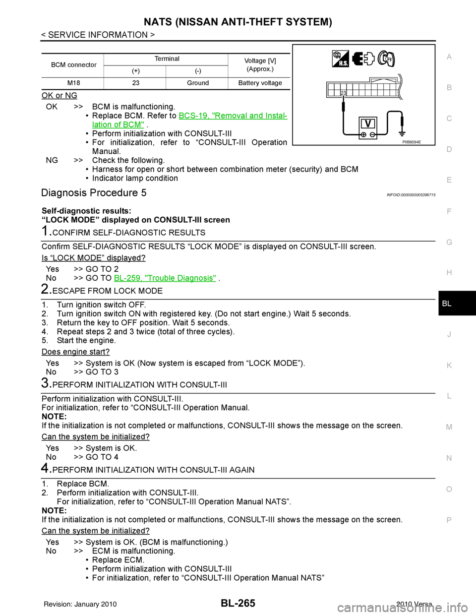
BCM connector Terminal
Voltage [V]
(Approx.)
(+) (-)
M18 23Ground Battery voltage
PIIB6594E
Revision: January 20102010 Versa