2010 NISSAN TIIDA differential
[x] Cancel search: differentialPage 382 of 3745

ASSEMBLYAT-365
< SERVICE INFORMATION >
DE
F
G H
I
J
K L
M A
B
AT
N
O P
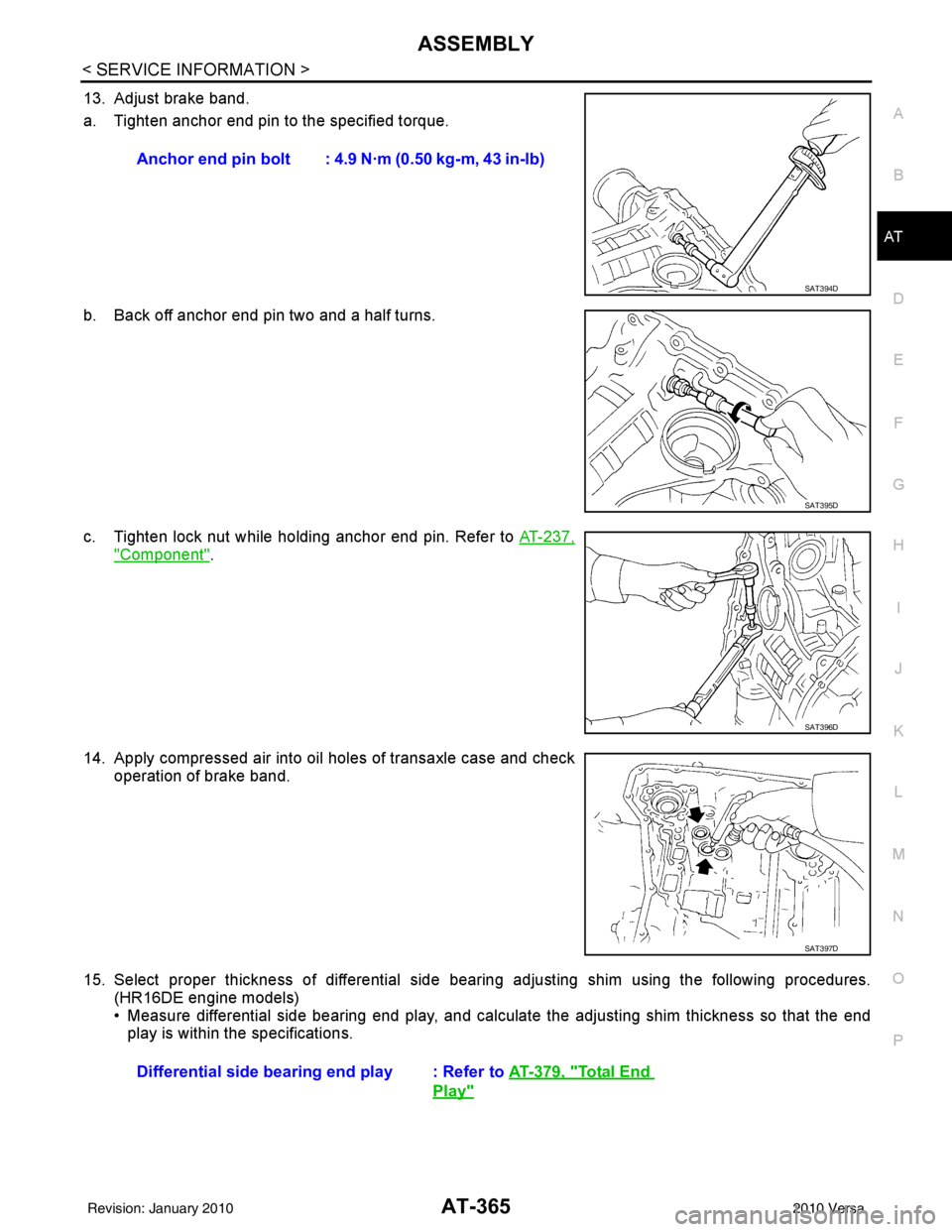
13. Adjust brake band.
a. Tighten anchor end pin to the specified torque.
b. Back off anchor end pin two and a half turns.
c. Tighten lock nut while holding anchor end pin. Refer to AT-237,
"Component".
14. Apply compressed air into oil holes of transaxle case and check operation of brake band.
15. Select proper thickness of differential side bear ing adjusting shim using the following procedures.
(HR16DE engine models)
• Measure differential side bearing end play, and calculat e the adjusting shim thickness so that the end
play is within the specifications. Anchor end pin bolt : 4.9 N·m (0.50 kg-m, 43 in-lb)
SAT394D
SAT395D
SAT396D
SAT397D
Differential side bearin
g end play : Refer to AT-379, "Total End
Play"
Revision: January 20102010 Versa
Page 383 of 3745

AT-366
< SERVICE INFORMATION >
ASSEMBLY
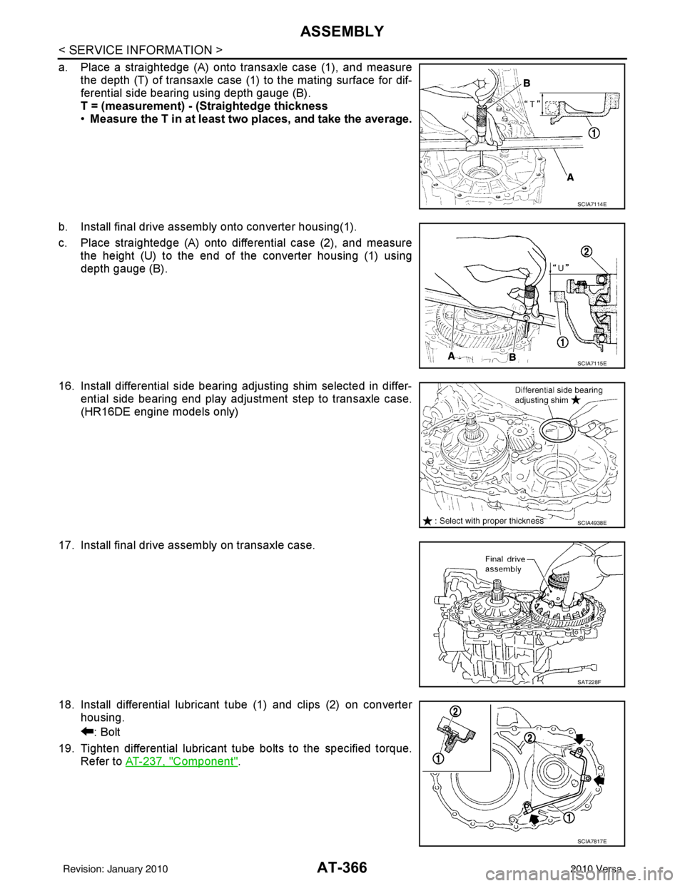
a. Place a straightedge (A) onto transaxle case (1), and measurethe depth (T) of transaxle case (1) to the mating surface for dif-
ferential side bearing using depth gauge (B).
T = (measurement) - (Straightedge thickness
•Measure the T in at least two places, and take the average.
b. Install final drive assembly onto converter housing(1).
c. Place straightedge (A) onto differential case (2), and measure the height (U) to the end of the converter housing (1) using
depth gauge (B).
16. Install differential side bearing adjusting shim selected in differ- ential side bearing end play adjustment step to transaxle case.
(HR16DE engine models only)
17. Install final drive assembly on transaxle case.
18. Install differential lubricant tube (1) and clips (2) on converter housing.
: Bolt
19. Tighten differential lubricant tube bolts to the specified torque. Refer to AT-237, "
Component".
SCIA7114E
SCIA7115E
SCIA4938E
SAT228F
SCIA7817E
Revision: January 20102010 Versa
Page 384 of 3745

ASSEMBLYAT-367
< SERVICE INFORMATION >
DE
F
G H
I
J
K L
M A
B
AT
N
O P
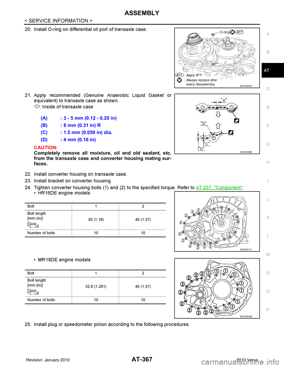
20. Install O-ring on differential oil port of transaxle case.
21. Apply recommended (Genuine Anaerobic Liquid Gasket or equivalent) to transaxle case as shown.
: Inside of transaxle case
CAUTION:
Completely remove all moisture, oil and old sealant, etc.
from the transaxle case and converter housing mating sur-
faces.
22. Install converter housing on transaxle case.
23. Install bracket on converter housing.
24. Tighten converter housing bolts (1) and (2) to the specified torque. Refer to AT-237, "
Component".
• HR16DE engine models
• MR18DE engine models
25. Install plug or speedometer pinion according to the following procedures.
SCIA3281E
(A) : 3 - 5 mm (0.12 - 0.20 in)
(B) : 8 mm (0.31 in) R
(C) : 1.5 mm (0.059 in) dia.
(D) : 4 mm (0.16 in)
SCIA7089E
Bolt 12
Bolt length
[mm (in)] 30 (1.18)40 (1.57)
Number of bolts 1010
SCIA6211J
Bolt 12
Bolt length
[mm (in)] 32.8 (1.291)40 (1.57)
Number of bolts 1010
SCIA7970E
Revision: January 20102010 Versa
Page 395 of 3745

AT-378
< SERVICE INFORMATION >
SERVICE DATA AND SPECIFICATIONS (SDS)
Final Drive
INFOID:0000000005397464
DIFFERENTIAL SIDE GEAR CLEARANCE
DIFFERENTIAL SIDE BEARING END PL AY (FOR HR16DE ENGINE MODELS)
BEARING PRELOAD (FOR MR18DE ENGINE MODELS)
TURNING TORQUE (FOR MR18DE ENGINE MODELS)
Planetary CarrierINFOID:0000000005397465
Oil PumpINFOID:0000000005397466
Input ShaftINFOID:0000000005397467
SEAL RING CLEARANCE
SEAL RING
Unit: mm (in)
Reduction Pinion GearINFOID:0000000005397468
TURNING TORQUE
Band ServoINFOID:0000000005397469
RETURN SPRINGS
Clearance between side gear and differential case with washer [mm (in)] 0.1 - 0.2 (0.004 - 0.008)
Differential side bearing end play mm (in)0 - 0.15 (0 - 0.0059)
Differential side bearing preload mm (in)0.05 - 0.09 (0.0020 - 0.0035)
Turning torque of final drive assembly N-m (kg-cm, in-lb)0.68 - 1.26 (7.0 - 13.0, 6.0 - 11.0)
Clearance between planetary carrier and pinion washer [mm (in)]Standard 0.15 - 0.70 (0.0059 - 0.0276)
Allowable limit
0.80 (0.0315)
Oil pump side clearance 0.02 - 0.04 (0.0008 - 0.0016)
Clearance between oil pump housing and outer gear [mm (in)] Standard
0.08 - 0.15 (0.0031 - 0.0059)
Allowable limit 0.15 (0.0059)
Oil pump cover seal ring clearance [mm (in)] Standard
0.10 - 0.25 (0.0039 - 0.0098)
Allowable limit 0.25 (0.0098)
Input shaft seal ring clearance [mm (in)] Standard 0.08 - 0.23 (0.0031 - 0.0091)
Allowable limit
0.23 (0.091)
Outer diameter Inner diameter Width
24 (0.94) 20.4 (0.803) 1.97 (0.0776)
Turning torque of reduction pinion gear [N·m (kg-m, in-lb)] 0.11 - 0.69 (0.01 - 0.07, 1 - 6)
Revision: January 20102010 Versa
Page 853 of 3745

NOISE, VIBRATION AND HARSHNESS (NVH) TROUBLESHOOTINGBR-5
< SERVICE INFORMATION >
C
DE
G H
I
J
K L
M A
B
BR
N
O P
NOISE, VIBRATION AND HARSHN ESS (NVH) TROUBLESHOOTING
NVH Troubleshooting ChartINFOID:0000000005396977
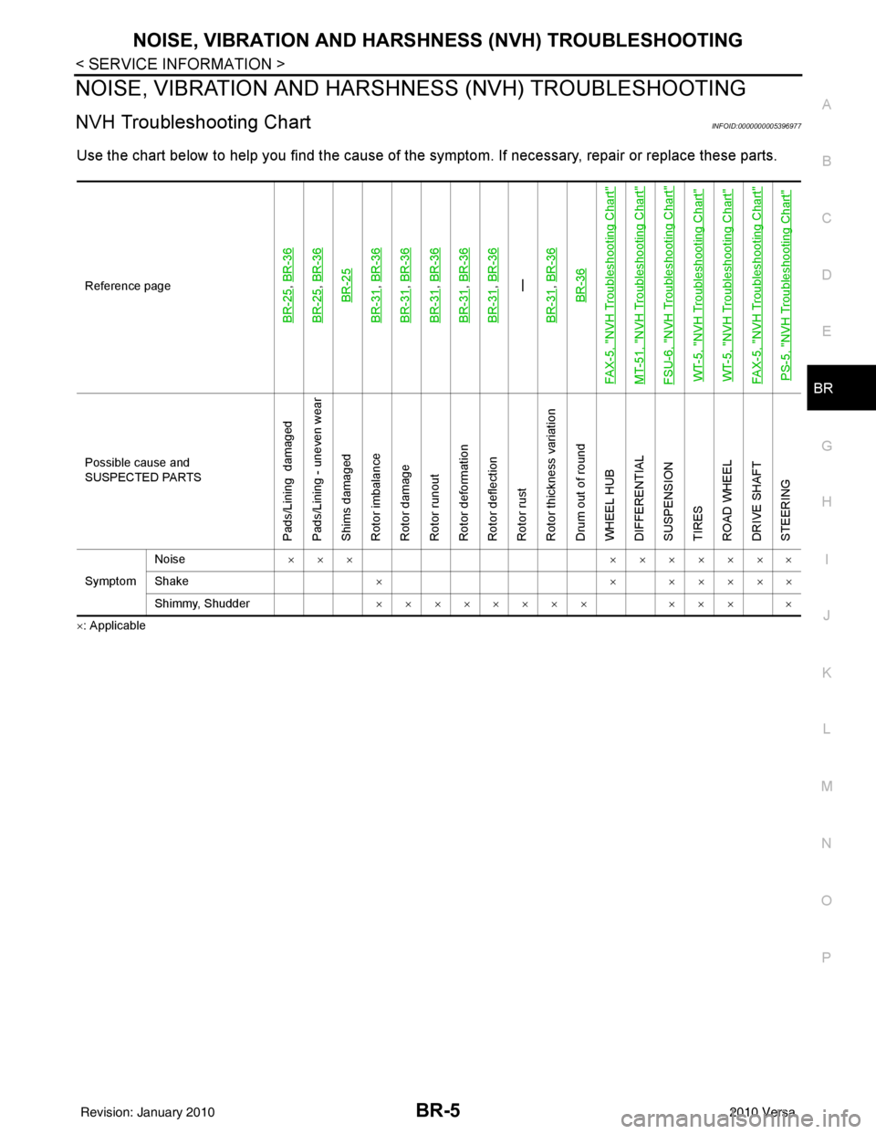
Use the chart below to help you find t he cause of the symptom. If necessary, repair or replace these parts.
×: ApplicableReference page
BR-25
,
BR-36
BR-25
, BR-36BR-25
BR-31
, BR-36
BR-31
, BR-36
BR-31
, BR-36
BR-31
, BR-36
BR-31
, BR-36—
BR-31, BR-36BR-36
FAX-5, "
NVH Troubleshooting Chart
"
MT-51, "
NVH Troubleshooting Chart
"
FSU-6, "
NVH Troubleshooting Chart
"
WT-5, "
NVH Troubleshooting Chart
"
WT-5, "
NVH Troubleshooting Chart
"
FAX-5, "
NVH Troubleshooting Chart
"
PS-5, "
NVH Troubleshooting Chart
"
Possible cause and
SUSPECTED PARTS
Pads/Lining damaged
Pads/Lining - uneven wear
Shims damaged
Rotor imbalance
Rotor damage
Rotor runout
Rotor deformation
Rotor deflection
Rotor rust
Rotor thickness variation
Drum out of round
WHEEL HUB
DIFFERENTIAL
SUSPENSION
TIRES
ROAD WHEEL
DRIVE SHAFT
STEERING
Symptom Noise
××× ×××××××
Shake × × ×××××
Shimmy, Shudder ×××××××× ××× ×
Revision: January 20102010 Versa
Page 1037 of 3745

CVT-4
CONSULT-III Reference Value in Data Monitor
Mode .................................................................... ..
135
Wiring Diagram - CVT - ODSW .............................136
Diagnosis Procedure .............................................136
Component Inspection ...........................................138
SHIFT POSITION INDICATOR CIRCUIT ........140
Description ........................................................... ..140
CONSULT-III Reference Value in Data Monitor
Mode .................................................................... ..
140
Diagnosis Procedure .............................................140
TROUBLE DIAGNOSIS FOR SYMPTOMS .....141
Wiring Diagram - CVT - NONDTC ....................... ..141
O/D OFF Indicator Lamp Does Not Come On .......143
Engine Cannot Be Started in "P" and "N" Position ..145
In "P" Position, Vehicle Moves Forward or Back-
ward When Pushed ...............................................
145
In "N" Position, Vehicle Moves ............................ ..146
Large Shock "N" → "R" Position .......................... ..146
Vehicle Does Not Creep Backward in "R" Position ..147
Vehicle Does Not Creep Forward in "D" or "L" Po-
sition ......................................................................
148
Vehicle Speed Does Not Change in "L" Position ...149
Vehicle Speed Does Not Change in overdrive-off
mode ......................................................................
150
Vehicle Speed Does Not Change in "D" Position ..151
Vehicle Does Not Decelerate by Engine Brake .....151
CVT SHIFT LOCK SYSTEM ........................... .153
Description ........................................................... ..153
Shift Lock System Electrical Parts Location ..........154
Wiring Diagram - CVT - SHIFT ..............................155
Diagnosis Procedure .............................................155
TCM ..................................................................159
Removal and Installation ..................................... ..159
SHIFT CONTROL SYSTEM ............................160
Removal and Installation .......................................160
CVT Shift Selector Disa ssembly and Assembly .. .163
Shift Lever Handle Removal and Installation ....... .163
Adjustment of CVT Position ................................. .164
Checking of CVT Position .....................................164
KEY INTERLOCK CABLE ...............................166
Removal and Installation .......................................166
PRIMARY SPEED SENSOR .......................... ..169
Exploded View ..................................................... .169
Removal and Installation .......................................169
Inspection ............................................................. .169
SECONDARY SPEED SENSOR ......................170
Exploded View ..................................................... .170
Removal and Installation .......................................170
Inspection ............................................................. .170
AIR BREATHER HOSE ....................................171
Removal and Installation .......................................171
DIFFERENTIAL SIDE OIL SEAL .....................172
Removal and Installation .......................................172
TRANSAXLE ASSEMBLY ............................. ..173
Removal and Installation .......................................173
SERVICE DATA AND SPECIFICATIONS
(SDS) .............................................................. ..
176
General Specification ........................................... .176
Vehicle Speed When Shifting Gears .....................176
Stall Speed ............................................................176
Line Pressure ........................................................176
Solenoid Valves ....................................................177
CVT Fluid Temperature Sensor ............................177
Primary Speed Sensor ..........................................177
Secondary Speed Sensor .................................... .177
Removal and Installation .......................................177
Revision: January 20102010 Versa
Page 1046 of 3745
![NISSAN TIIDA 2010 Service Repair Manual PREPARATIONCVT-13
< SERVICE INFORMATION > [RE0F08B]
D
E
F
G H
I
J
K L
M A
B
CVT
N
O P
PREPARATION
Special Service ToolINFOID:0000000005397765
The actual shapes of Kent-Moore tools may differ from thos NISSAN TIIDA 2010 Service Repair Manual PREPARATIONCVT-13
< SERVICE INFORMATION > [RE0F08B]
D
E
F
G H
I
J
K L
M A
B
CVT
N
O P
PREPARATION
Special Service ToolINFOID:0000000005397765
The actual shapes of Kent-Moore tools may differ from thos](/manual-img/5/57397/w960_57397-1045.png)
PREPARATIONCVT-13
< SERVICE INFORMATION > [RE0F08B]
D
E
F
G H
I
J
K L
M A
B
CVT
N
O P
PREPARATION
Special Service ToolINFOID:0000000005397765
The actual shapes of Kent-Moore tools may differ from those of special service tools illustrated here.
Commercial Service ToolINFOID:0000000005397766
Tool number
(Kent-Moore No.)
Tool name Description
—
(OTC3492)
Oil pressure gauge set Measuring line pressure
—
(J-47244)
Drift Installing differential side oil seal
• Transaxle case side (left)
a: 65.83 mm (2.59 in) dia.
b: 53.85 mm (2.12 in) dia.
ST33400001
(J-47005)
Drift Installing differential side oil seal
• Converter housing side (right)
a: 69.85 mm (2.75 in) dia.
b: 49.53 mm (1.95 in) dia.
—
( J-46534 )
Trim tool set For removing trim
SCIA7531E
SCIA5777E
SCIA5777E
AWJIA0483ZZ
Tool number
Tool name
Description
Power tool Loosening nuts and bolts
PBIC0190E
Revision: January 20102010 Versa
Page 1052 of 3745
![NISSAN TIIDA 2010 Service Repair Manual CVT SYSTEMCVT-19
< SERVICE INFORMATION > [RE0F08B]
D
E
F
G H
I
J
K L
M A
B
CVT
N
O P
CVT SYSTEM
Cross-Sectional View - RE0F08BINFOID:0000000005397770
1. Converter housing 2. Oil pump3. Forward clutch
NISSAN TIIDA 2010 Service Repair Manual CVT SYSTEMCVT-19
< SERVICE INFORMATION > [RE0F08B]
D
E
F
G H
I
J
K L
M A
B
CVT
N
O P
CVT SYSTEM
Cross-Sectional View - RE0F08BINFOID:0000000005397770
1. Converter housing 2. Oil pump3. Forward clutch](/manual-img/5/57397/w960_57397-1051.png)
CVT SYSTEMCVT-19
< SERVICE INFORMATION > [RE0F08B]
D
E
F
G H
I
J
K L
M A
B
CVT
N
O P
CVT SYSTEM
Cross-Sectional View - RE0F08BINFOID:0000000005397770
1. Converter housing 2. Oil pump3. Forward clutch
4. Reverse brake 5. Planetary carrier6. Primary pulley
7. Steel belt 8. Sun gear9. Side cover
10. Internal gear 11. Secondary pulley12. Differential case
13. Final gear 14. Idler gear15. Reduction gear
16. Output gear 17. Parking gear18. Input shaft
19. Torque converter
SCIA8015E
Revision: January 20102010 Versa