Page 2699 of 3745
SERVICE INFORMATION FOR ELECTRICAL INCIDENTGI-33
< SERVICE INFORMATION >
C
DE
F
G H
I
J
K L
M B
GI
N
O P
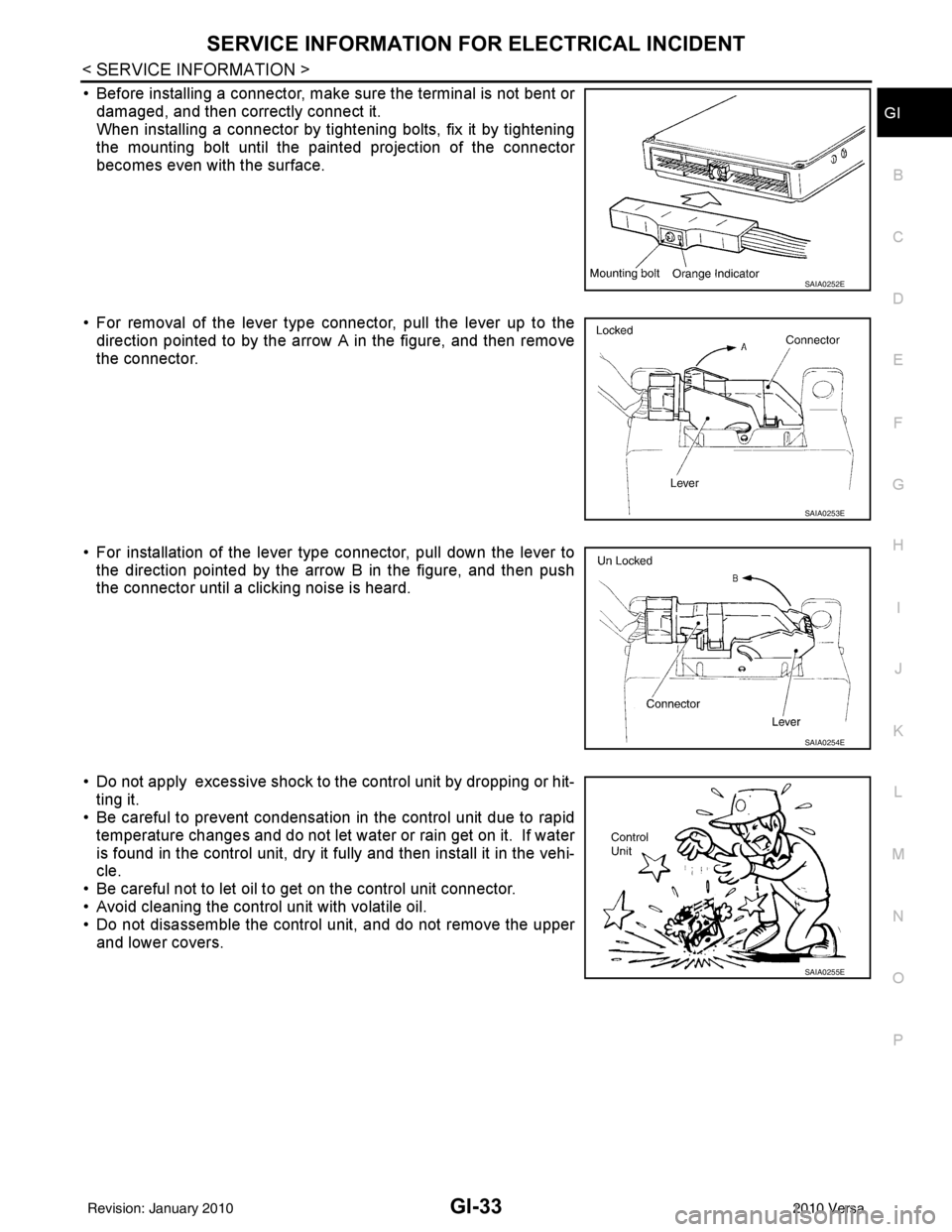
• Before installing a connector, make sure the terminal is not bent or damaged, and then correctly connect it.
When installing a connector by tightening bolts, fix it by tightening
the mounting bolt until the painted projection of the connector
becomes even with the surface.
• For removal of the lever type connector, pull the lever up to the direction pointed to by the arrow A in the figure, and then remove
the connector.
• For installation of the lever type connector, pull down the lever to the direction pointed by the arrow B in the figure, and then push
the connector until a clicking noise is heard.
• Do not apply excessive shock to the control unit by dropping or hit- ting it.
• Be careful to prevent condensation in the control unit due to rapid
temperature changes and do not let water or rain get on it. If water
is found in the control unit, dry it fully and then install it in the vehi-
cle.
• Be careful not to let oil to get on the control unit connector.
• Avoid cleaning the control unit with volatile oil.
• Do not disassemble the control unit, and do not remove the upper and lower covers.
SAIA0252E
SAIA0253E
SAIA0254E
SAIA0255E
Revision: January 20102010 Versa
Page 2704 of 3745
GI-38
< SERVICE INFORMATION >
LIFTING POINT
LIFTING POINT
Special Service ToolINFOID:0000000005399857
CAUTION:
• Every time the vehicle is lifted up, maintain the complete vehicle curb condition.
• Since the vehicle's center of gravity changes when removing main parts on the front side (engine,
transmission, suspension etc.), support a jack up point on the rear side garage jack with a mission
jack or equivalent.
• Since the vehicle's center of gravity changes when removing main parts on the rear side (rear axle,
suspension, etc.), support a jack up point on the front side garage jack with a mission jack or equiv-
alent.
• Be careful not to smash or do not do an ything that would affect piping parts.
Garage Jack and Safety Stand and 2-Pole LiftINFOID:0000000005399858
WARNING:
• Park the vehicle on a level surface when using the jack. Make sure to avoid damaging pipes, tubes,
etc. under the vehicle.
• Never get under the vehicle while it is supported only by the jack. Always use safety stands when you have to get under the vehicle.
• Place wheel chocks at both front an d back of the wheels on the ground.
• When lifting the vehicle, open the lift arms as wid e as possible and ensure that the front and rear of
the vehicle are well balanced.
• When setting the lift arm, do not allow the arm to contact the brake tubes, brake cable, fuel lines and
sill spoiler.
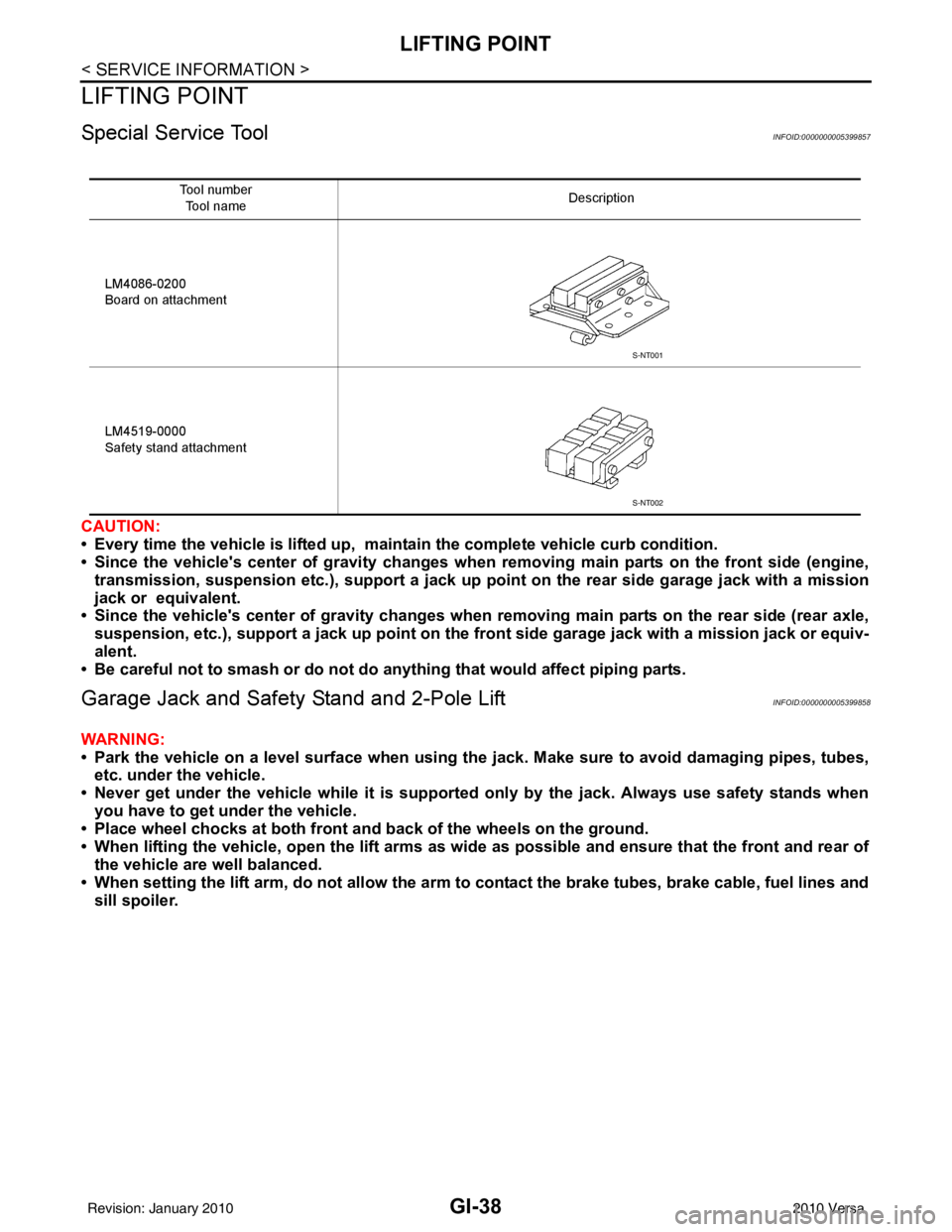
Tool number
Tool name Description
LM4086-0200
Board on attachment
LM4519-0000
Safety stand attachment
S-NT001
S-NT002
Revision: January 20102010 Versa
Page 3123 of 3745
SERVICE DATA AND SPECIFICATIONS (SDS)LU-11
< SERVICE DATA AND SPECIFICATIONS (SDS) [HR16DE]
C
D
E
F
G H
I
J
K L
M A
LU
NP
O
SERVICE DATA AND SPECIFICATIONS (SDS)
SERVICE DATA AND SPECIFICATIONS (SDS)
Engine Oil CapacityINFOID:0000000005398161
Unit: (US qt, lmp qt)
Engine Oil PressureINFOID:0000000005398162
Unit: kPa (bar, kg/cm2, psi)
*: Engine oil temperature at 80
°C (176 °F)
Drain and refill With oil filter change
Approximately 3.0 (3 1/8, 2 5/8)
Without oil filter change Approximately 2.8 (3, 2 1/2)
Dry engine (engine overhaul) Approximately 3.5 (3 3/4, 3 1/8)
Engine speed Approximate discharge oil pressure*
Idle speed More than 60 (0.60, 0.61, 9)
2,000 rpm More than 270 (2.7, 2.8, 39)
Revision: January 20102010 Versa
Page 3135 of 3745
SERVICE DATA AND SPECIFICATIONS (SDS)LU-23
< SERVICE INFORMATION > [MR18DE]
C
D
E
F
G H
I
J
K L
M A
LU
NP
O
SERVICE DATA AND SPECIFICATIONS (SDS)
Standard and LimitINFOID:0000000005398174
ENGINE OIL PRESSURE
Unit: kPa (bar, kg/cm2, psi)
ENGINE OIL CAPACITY
Unit: (US qt, Imp qt)
Engine speed
Approximate discharge oil pressure
Idle speed 60 (0.60, 0.61, 9)
2,000 rpm 200 (2.0, 2.0, 29)
Drain and refillWith oil filter change Approximately 4.1 (4 3/8, 3 5/8)
Without oil filter change
Approximately 3.9 (4 1/8, 3 3/8)
Dry engine (engine overhaul) Approximately 4.9 (5 1/8, 4 3/8)
Revision: January 20102010 Versa
Page 3149 of 3745

MA-14
< SERVICE INFORMATION >
RECOMMENDED FLUIDS AND LUBRICANTS
RECOMMENDED FLUIDS AND LUBRICANTS
Fluids and LubricantsINFOID:0000000005394798
*1: For further details, see “Engine Oil Recommendation”.
*2: If genuine NISSAN gear oil is not available, API GL-4, Viscosity SAE 75W-80 may be used as a temporary replacement. However
use Genuine NISSAN gear oil as soon as it is possible.
*3: Using transaxle fluid other than Genuine NISSAN CVT Fluid NS-2 will damage the CVT, which is not covered by the NISSAN
new vehicle limited warranty.
*4: Available in mainland U.S.A. through a NISSAN dealer.
*5: For further details, see “Air conditioner specification label”.
*6: If Genuine NISSAN Matic S ATF is not available, Genuine NISSIAN Matic D ATF may also be used. Using automatic transmission
other than Genuine NISSAN Matic S or Genuine NISSIAN Matic D ATF will cause deteri oration in driveability and automatic transmis-
sion durability, and may damage the automatic transmission, which is not covered by NISSAN new vehicle limited warranty.
SAE Viscosity NumberINFOID:0000000005394799
NISSAN recommends the use of an energy conservi ng oil in order to improve fuel economy.
DescriptionCapacity (Approximate)
Recommended Fluids/Lubricants
Liter US measure Imp measure
Fuel 50.0 13 1/4 gal 11 galUnleaded gasoline with an octane rat-
ing of at least 87 AKI (RON 91)
Engine oil
Drain and refill With oil filter
change
HR16DE 3.0 3 1/8 qt 2 5/8 qt
• Engine oil with API Certification Mark *1
• Viscosity SAE 5W-30
MR18DE 4.1 4 3/8 qt 3 5/8 qt
Without oil
filter change HR16DE 2.8
3 qt 2 1/2 qt
MR18DE 3.9 4 1/8 qt 3 3/8 qt
Dry engine (engine overhaul) HR16DE 3.5 3 3/4 qt 3 1/8 qt
MR18DE 4.9 5 1/8 qt 4 3/8 qt
Cooling system
(with reservoir at max level) HR16DE 6.3 6 5/8 qt 5 1/2 qt Genuine
NISSAN Long Life Anti-freeze
Coolant or equivalent
MR18DE 6.8 7 1/4 qt 6 qt
Manual transaxle fluid (MTF) 5MT
2.6 5 1/2 pt 4 5/8 pt Genuine NISSAN Manual Transmis-
sion Fluid (MTF) HQ Multi 75W-85 or
API GL-4, Viscosity SAE 75W-85
6MT 2.0 4 1/4 pt 3 1/2 pt Genuine NISSAN gear oil (XT4447
M+) 75W-80, Genuine NISSAN gear oil
(ETL8997B) 75W-80, or equivalent *2
Automatic transaxle fluid (ATF) HR16DE 7.7 8 1/8 qt 6 3/4 qt
Genuine NISSAN Matic S ATF recom-
mended *6
MR18DE 7.9 8 3/8 qt 7 qt
CVT fluid RE0F08B 7.4 7 7/8 qt 6 1/2 qt Genuine NISSAN CVT Fluid NS-2 *3
Brake and clutch fluid ———Genuine NISSAN Su
per Heavy Duty
Brake Fluid*4 or equivalent DOT 3 (US
FMVSS No. 116)
Multi-purpose grease ——— NLGI No. 2 (Lithium soap base)
Windshield washer fluid 4.5 4 3/4 qt 4 qtGenuine NISSAN Windshield Washer
Concentrate Cleaner & Anti-Freeze or
equivalent
Air conditioning system refrigerant 0.45 ± 0.05 kg 0.99 ± 0.11 lb 0.99 ± 0.11 lb HFC-134a (R-134a) *5
Air conditioning system oil MR18DE
Type 1 and
HR16DE
120 m
4.1 fl oz 4.2 fl oz NISSAN A/C System Lubricant Type R
or equivalent *5
MR18DE
Typ e 2 100 m
3.4 fl oz 3.5 fl oz NISSAN A/C System Lubricant Type S
or equivalent *5
Revision: January 20102010 Versa
Page 3170 of 3745
ENGINE MAINTENANCE (MR18DE)MA-35
< SERVICE INFORMATION >
C
DE
F
G H
I
J
K
M A
B
MA
N
O P
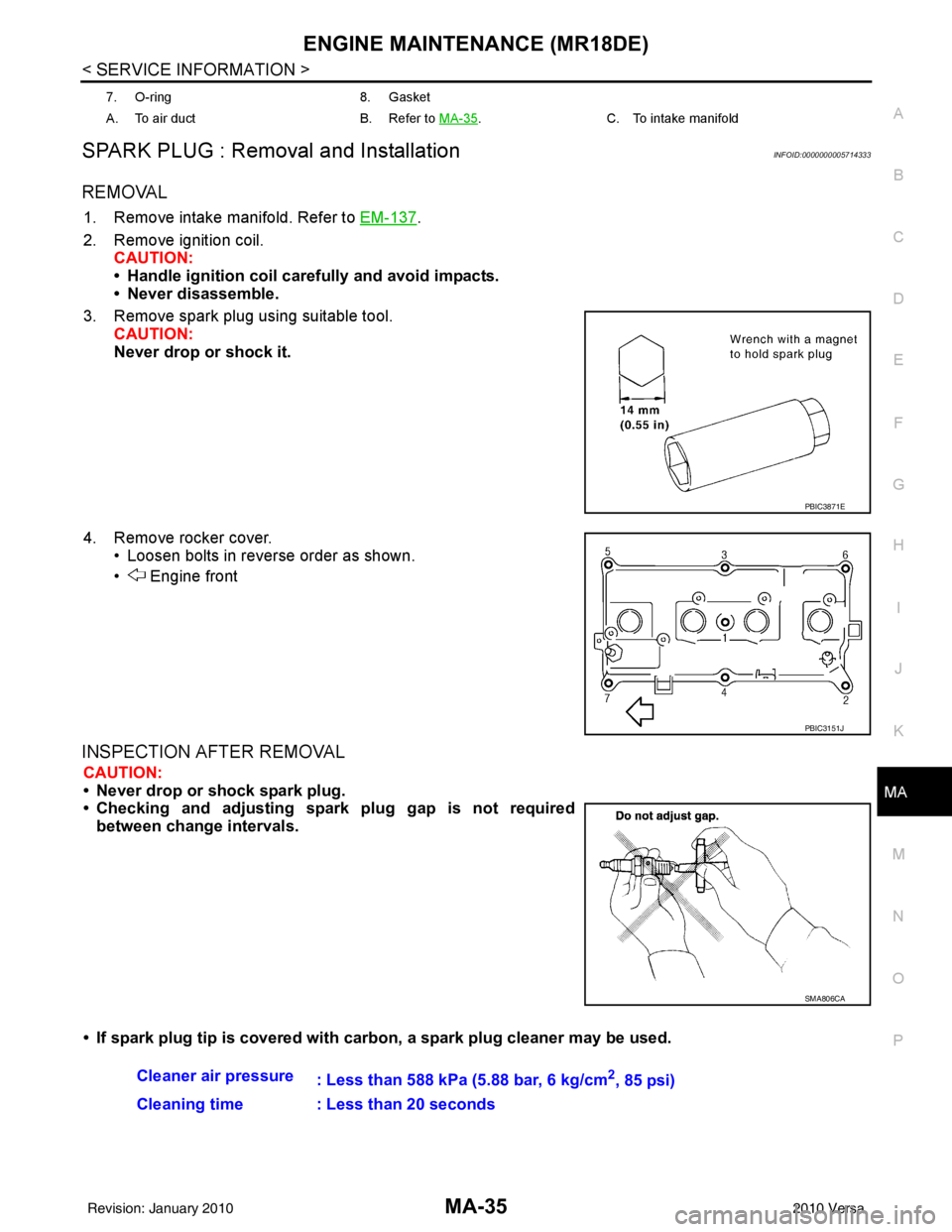
SPARK PLUG : Removal and InstallationINFOID:0000000005714333
REMOVAL
1. Remove intake manifold. Refer to EM-137.
2. Remove ignition coil. CAUTION:
• Handle ignition coil car efully and avoid impacts.
• Never disassemble.
3. Remove spark plug using suitable tool. CAUTION:
Never drop or shock it.
4. Remove rocker cover. • Loosen bolts in reverse order as shown.
• Engine front
INSPECTION AFTER REMOVAL
CAUTION:
• Never drop or shock spark plug.
• Checking and adjusting spar k plug gap is not required
between change intervals.
• If spark plug tip is covered with carbon, a spark plug cleaner may be used.
7. O-ring8. Gasket
A. To air duct B. Refer to MA-35
.C. To intake manifold
PBIC3871E
PBIC3151J
SMA806CA
Cleaner air pressure
: Less than 588 kPa (5.88 bar, 6 kg/cm2, 85 psi)
Cleaning time : Less than 20 seconds
Revision: January 20102010 Versa
Page 3290 of 3745
PREPARATIONMTC-11
< SERVICE INFORMATION >
C
DE
F
G H
I
K L
M A
B
MTC
N
O P
PREPARATION
HFC-134a (R-134a) Service Tool and EquipmentINFOID:0000000005396482
Never mix HFC-134a refrigerant and/or its specified oil with CFC-12 (R-12) refrigerant and/or its oil.
Separate and non-interchangeable service equipment must be used for handling each type of refrigerant/oil.
Refrigerant container fittings, service hose fittings and service equipment fittings (equipment which handles
refrigerant and/or oil) are different between CFC-12 (R-12) and HFC-134a (R-134a). This is to avoid mixed
use of the refrigerants/oil.
Adapters that convert one size fitting to another must never be used refrigerant/oil contamination will occur
and compressor failure will result.
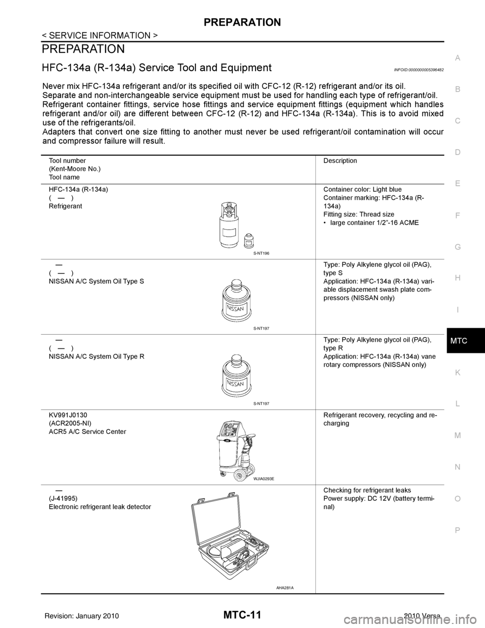
Tool number
(Kent-Moore No.)
Tool name Description
HFC-134a (R-134a)
(—)
Refrigerant Container color: Light blue
Container marking: HFC-134a (R-
134a)
Fitting size: Thread size
• large container 1/2”-16 ACME
—
(—)
NISSAN A/C System Oil Type S Type: Poly Alkylene glycol oil (PAG),
type S
Application: HFC-134a (R-134a) vari-
able displacement swash plate com-
pressors (NISSAN only)
—
(—)
NISSAN A/C System Oil Type R Type: Poly Alkylene glycol oil (PAG),
type R
Application: HFC-134a (R-134a) vane
rotary compressors (NISSAN only)
KV991J0130
(ACR2005-NI)
ACR5 A/C Se rvice Center Refrigerant recovery, recycling and re-
charging
—
(J-41995)
Electronic refrigerant leak detector Checking for refrigerant leaks
Power supply: DC 12V (battery termi-
nal)
S-NT196
S-NT197
S-NT197
WJIA0293E
AHA281A
Revision: January 20102010 Versa
Page 3296 of 3745
OIL
MTC-17
< SERVICE INFORMATION >
C
D E
F
G H
I
K L
M A
B
MTC
N
O P
OIL
Maintenance of Oil Qu antity in CompressorINFOID:0000000005396487
The oil in the compressor circulates through the system with the refrigerant. Add oil to compressor when
replacing any component or after a large refrigerant leakage occurred. It is important to maintain the specified
amount.
If oil quantity is not maintained properly , the following malfunctions may result:
• Lack of oil: May lead to a seized compressor.
• Excessive oil: Inadequate cooling (thermal exchange interference)
OIL
OIL ADJUSTING PROCEDURE FOR COMPONENTS REPLACEMENT EXCEPT COMPRESSOR
After replacing any of the following major components, add the correct amount of oil to the system.
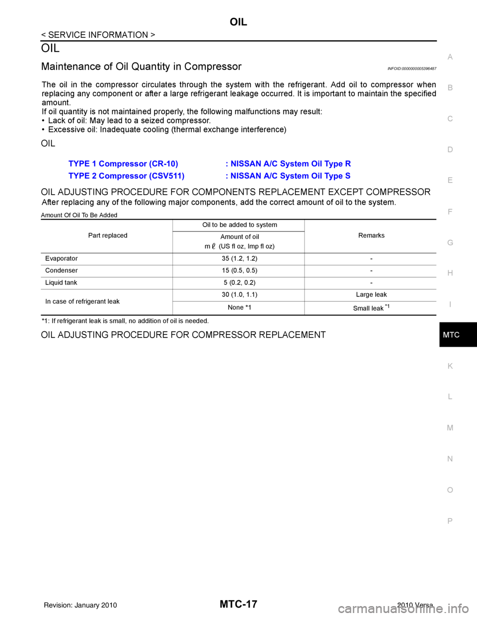
Amount Of Oil To Be Added
*1: If refrigerant leak is small, no addition of oil is needed.
OIL ADJUSTING PROCEDURE FOR COMPRESSOR REPLACEMENT
TYPE 1 Compressor (CR-10) : NISSAN A/C System Oil Type R
TYPE 2 Compressor (CSV511) : NISSAN A/C System Oil Type S
Part replaced Oil to be added to system
Remarks
Amount of oil
m (US fl oz, Imp fl oz)
Evaporator 35 (1.2, 1.2)-
Condenser 15 (0.5, 0.5)-
Liquid tank 5 (0.2, 0.2)-
In case of refrigerant leak 30 (1.0, 1.1)
Large leak
None *1 Small leak
*1
Revision: January 20102010 Versa
![NISSAN TIIDA 2010 Service Repair Manual SERVICE DATA AND SPECIFICATIONS (SDS)LU-11
< SERVICE DATA AND SPECIFICATIONS (SDS) [HR16DE]
C
D
E
F
G H
I
J
K L
M A
LU
NP
O
SERVICE DATA AND SPECIFICATIONS (SDS)
SERVICE DATA AND SPECIFICATIONS (SDS)](/manual-img/5/57397/w960_57397-3122.png "NISSAN TIIDA 2010 Service Repair Manual SERVICE DATA AND SPECIFICATIONS (SDS)LU-11
< SERVICE DATA AND SPECIFICATIONS (SDS) [HR16DE]
C
D
E
F
G H
I
J
K L
M A
LU
NP
O
SERVICE DATA AND SPECIFICATIONS (SDS)
SERVICE DATA AND SPECIFICATIONS (SDS)")
![NISSAN TIIDA 2010 Service Repair Manual SERVICE DATA AND SPECIFICATIONS (SDS)LU-23
< SERVICE INFORMATION > [MR18DE]
C
D
E
F
G H
I
J
K L
M A
LU
NP
O
SERVICE DATA AND SPECIFICATIONS (SDS)
Standard and LimitINFOID:0000000005398174
ENGINE OIL P](/manual-img/5/57397/w960_57397-3134.png "NISSAN TIIDA 2010 Service Repair Manual SERVICE DATA AND SPECIFICATIONS (SDS)LU-23
< SERVICE INFORMATION > [MR18DE]
C
D
E
F
G H
I
J
K L
M A
LU
NP
O
SERVICE DATA AND SPECIFICATIONS (SDS)
Standard and LimitINFOID:0000000005398174
ENGINE OIL P")