2010 NISSAN TIIDA fuse box
[x] Cancel search: fuse boxPage 3037 of 3745

LT-42
< SERVICE INFORMATION >
FRONT FOG LAMP
FRONT FOG LAMP
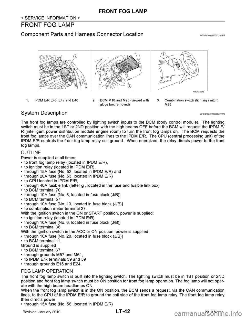
Component Parts and Harness Connector LocationINFOID:0000000005394912
System DescriptionINFOID:0000000005394913
The front fog lamps are controlled by lighting switch inputs to the BCM (body control module). The lighting
switch must be in the 1ST or 2ND position with t he high beams OFF before the BCM will request the IPDM E/
R (intelligent power distribution module engine room) to turn the front fog lamps on. The BCM requests the
front fog lamps over the CAN communication lines to the IPDM E/R. The CPU (central processing unit) of the
IPDM E/R controls the front fog lamp relay coil ground. When energized, the relay directs power to the front
fog lamps.
OUTLINE
Power is supplied at all times:
• to front fog lamp relay (located in IPDM E/R),
• to ignition relay (located in IPDM E/R),
• through 15A fuse (No. 52, located in IPDM E/R) and
• through 20A fuse (No. 53, located in IPDM E/R)
• to CPU located in IPDM E/R,
• through 40A fusible link (letter g , located in the fuse and fusible link box)
• to BCM terminal 70,
• through 10A fuse [No. 8, located in fuse block (J/B)]
• to BCM terminal 57,
• through 10A fuse [No. 13, located in fuse block (J/B)]
• to combination meter terminal 27.
With the ignition switch in the ON or START position, power is supplied:
• to ignition relay (located in IPDM E/R),
• through 10A fuse [No. 6, located in fuse block (J/B)]
• to BCM terminal 38.
With the ignition switch in the ACC or ON position, power is supplied
• through 10A fuse [No. 20, located in fuse block (J/B)]
• to BCM terminal 11.
Ground is supplied
• to BCM terminal 67
• through grounds M57 and M61,
• to IPDM E/R terminals 39 and 59
• through grounds E15 and E24.
FOG LAMP OPERATION
The front fog lamp switch is built into the lighting s witch. The lighting switch must be in 1ST position or 2ND
position and front fog lamp switch must be ON position fo r front fog lamp operation. The fog lamp will not oper-
ate with the high beam headlamps ON.
When the front fog lamp switch is in the ON positi on, the BCM sends a request, via the CAN communication
lines, to the CPU of the IPDM E/R to ground the coil side of the front fog lamp relay. The front fog lamp relay
then directs power
• through 15A fuse (No. 56, located in IPDM E/R)
1. IPDM E/R E46, E47 and E48 2. BCM M18 and M20 (viewed with
glove box removed)3. Combination switch (lighting switch)
M28
WKIA5554E
Revision: January 20102010 Versa
Page 3046 of 3745

TURN SIGNAL AND HAZARD WARNING LAMPSLT-51
< SERVICE INFORMATION >
C
DE
F
G H
I
J
L
M A
B
LT
N
O P
TURN SIGNAL AND HA ZARD WARNING LAMPS
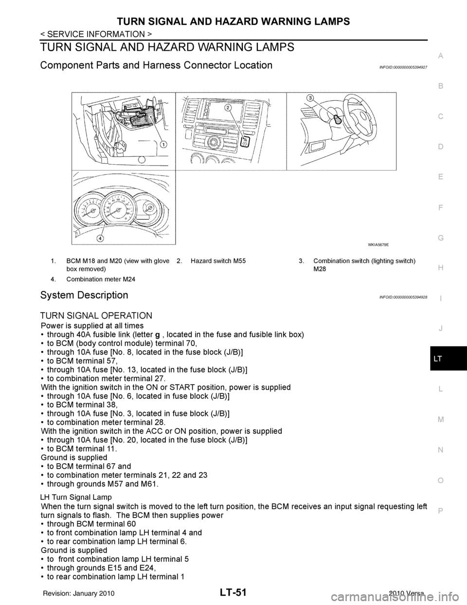
Component Parts and Har ness Connector LocationINFOID:0000000005394927
System DescriptionINFOID:0000000005394928
TURN SIGNAL OPERATION
Power is supplied at all times
• through 40A fusible link (letter g , located in the fuse and fusible link box)
• to BCM (body control module) terminal 70,
• through 10A fuse [No. 8, located in the fuse block (J/B)]
• to BCM terminal 57,
• through 10A fuse [No. 13, located in the fuse block (J/B)]
• to combination meter terminal 27.
With the ignition switch in the ON or START position, power is supplied
• through 10A fuse [No. 6, located in fuse block (J/B)]
• to BCM terminal 38,
• through 10A fuse [No. 3, located in fuse block (J/B)]
• to combination meter terminal 28.
With the ignition switch in the ACC or ON position, power is supplied
• through 10A fuse [No. 20, located in the fuse block (J/B)]
• to BCM terminal 11.
Ground is supplied
• to BCM terminal 67 and
• to combination meter terminals 21, 22 and 23
• through grounds M57 and M61.
LH Turn Signal Lamp
When the turn signal switch is moved to the left turn position, the BCM receives an input signal requesting left
turn signals to flash. The BCM then supplies power
• through BCM terminal 60
• to front combination lamp LH terminal 4 and
• to rear combination lamp LH terminal 6.
Ground is supplied
• to front combination lamp LH terminal 5
• through grounds E15 and E24,
• to rear combination lamp LH terminal 1
1. BCM M18 and M20 (view with glove
box removed) 2. Hazard switch M55
3. Combination switch (lighting switch)
M28
4. Combination meter M24
WKIA5679E
Revision: January 20102010 Versa
Page 3047 of 3745

LT-52
< SERVICE INFORMATION >
TURN SIGNAL AND HAZARD WARNING LAMPS
• through grounds B7 and B19.
The BCM also sends a request, via the CAN communication lines, to the combination meter to flash the left
turn signal indicator. The unified meter control unit in the combination meter supplies ground to the left turn
signal indicator lamp and activates the audible turn signal indicator.
With power, ground and input supplied, the BCM controls the flashing of the turn signal lamps.
RH Turn Signal Lamp
When turn signal switch is moved to the right turn position, the BCM receives an input signal requesting right
turn signals to flash. The BCM then supplies power
• through BCM terminal 61
• to front combination lamp RH terminal 4 and
• to rear combination lamp RH terminal 6.
Ground is supplied
• to front combination lamp RH terminal 5
• through grounds E15 and E24,
• to rear combination lamp RH terminal 1
• through grounds B117, B132 (all m odels) and D402 (with hatchback).
The BCM also sends a request, via the CAN communication lines, to the combination meter to flash the right
turn signal indicator. The unified meter control unit in the combination meter supplies ground to the right turn
signal indicator lamp and activates the audible turn signal indicator.
With power, ground and input supplied, the BCM cont rols the flashing of the turn signal lamps.
HAZARD LAMP OPERATION
Power is supplied at all times
• through 40A fusible link (letter g , located in fuse, fusible link and relay box)
• to BCM terminal 70,
• through 10A fuse [No. 8, located in fuse block (J/B)]
• to BCM terminal 57,
• through 10A fuse [No. 13, located in fuse block (J/B)]
• to combination meter terminal 27.
Ground is supplied
• to hazard switch terminal 1,
• to BCM terminal 67, and
• to combination meter terminals 21, 22 and 23
• through grounds M57 and M61.
When hazard switch is depressed, ground is supplied
• through hazard switch terminal 2
• to BCM terminal 29.
BCM then supplies power
• to front combination lamp LH terminal 4 and
• to rear combination lamp LH terminal 6
• through BCM terminal 60,
• to front combination lamp RH terminal 4 and
• to rear combination lamp RH terminal 6
• through BCM terminal 61.
Ground is supplied
• to front combination lamp LH and RH terminal 5
• through grounds E15 and E24,
• to rear combination lamp LH terminal 1
• through grounds B7 and B19,
• to rear combination lamp RH terminal 1
• through grounds B117, B132 and D402 (hatchback).
The BCM also supplies input to combination meter across the CAN communication lines. This input is pro-
cessed by unified meter control unit in combination meter, which in turn supplies ground to the left and right
turn signal indicator lamps.
With power and input supplied, BCM cont rols flashing of hazard warning lamps.
REMOTE KEYLESS ENTRY SYSTEM OPERATION
Power is supplied at all times
• through 40A fusible link (letter g , located in fuse, fusible link and relay box)
• to BCM terminal 70,
• through 10A fuse [No. 13, located in fuse block (J/B)]
Revision: January 20102010 Versa
Page 3070 of 3745

PARKING, LICENSE PLATE AND TAIL LAMPS
LT-75
< SERVICE INFORMATION >
C
D E
F
G H
I
J
L
M A
B
LT
N
O P
PARKING, LICENSE PLATE AND TAIL LAMPS
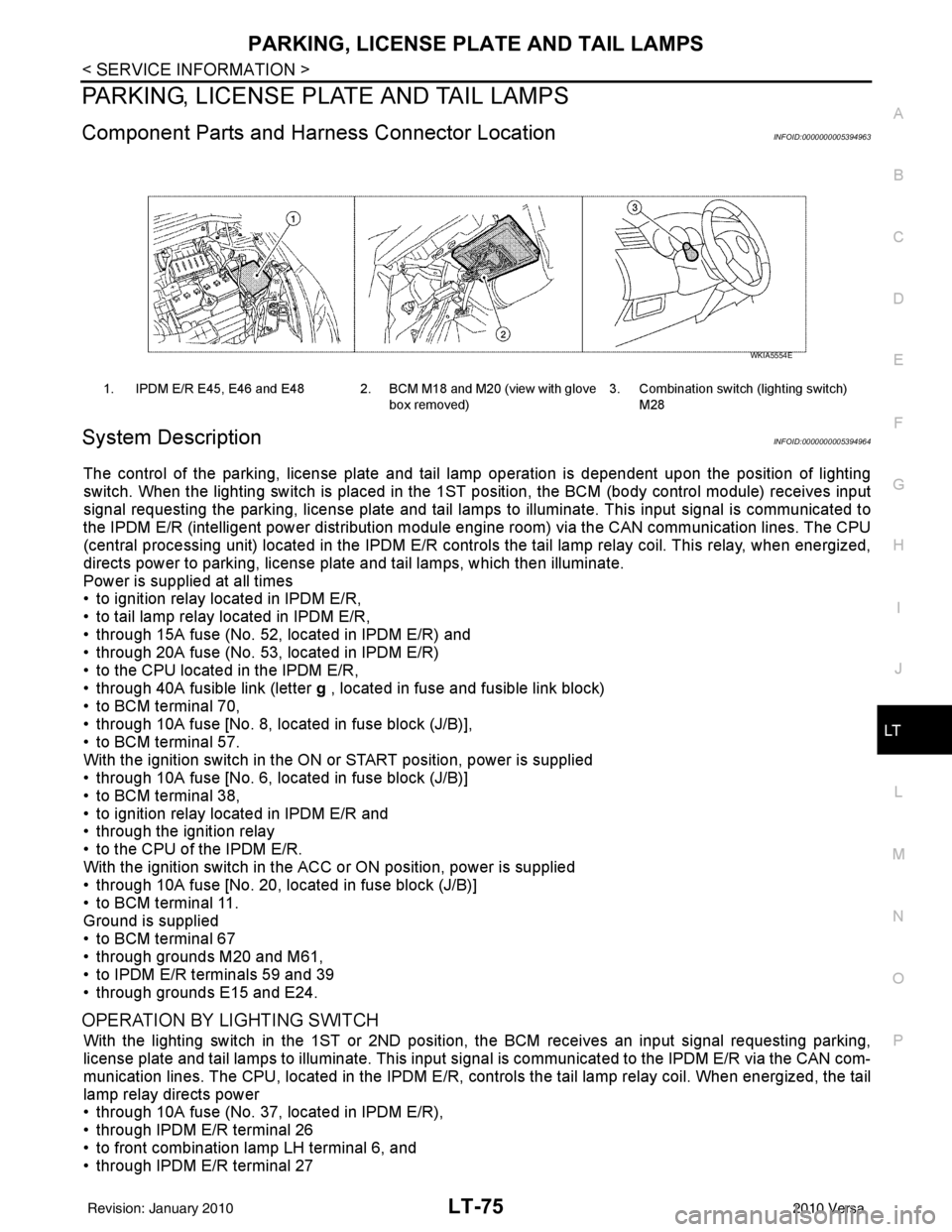
Component Parts and Har ness Connector LocationINFOID:0000000005394963
System DescriptionINFOID:0000000005394964
The control of the parking, license plate and tail lamp operation is dependent upon the position of lighting
switch. When the lighting switch is placed in the 1ST position, the BCM (body control module) receives input
signal requesting the parking, license plate and tail lamps to illuminate. This input signal is communicated to
the IPDM E/R (intelligent power distribution module engine room) via the CAN communication lines. The CPU
(central processing unit) located in the IPDM E/R contro ls the tail lamp relay coil. This relay, when energized,
directs power to parking, license plate and tail lamps, which then illuminate.
Power is supplied at all times
• to ignition relay located in IPDM E/R,
• to tail lamp relay located in IPDM E/R,
• through 15A fuse (No. 52, located in IPDM E/R) and
• through 20A fuse (No. 53, located in IPDM E/R)
• to the CPU located in the IPDM E/R,
• through 40A fusible link (letter g , located in fuse and fusible link block)
• to BCM terminal 70,
• through 10A fuse [No. 8, located in fuse block (J/B)],
• to BCM terminal 57.
With the ignition switch in the ON or START position, power is supplied
• through 10A fuse [No. 6, located in fuse block (J/B)]
• to BCM terminal 38,
• to ignition relay located in IPDM E/R and
• through the ignition relay
• to the CPU of the IPDM E/R.
With the ignition switch in the ACC or ON position, power is supplied
• through 10A fuse [No. 20, located in fuse block (J/B)]
• to BCM terminal 11.
Ground is supplied
• to BCM terminal 67
• through grounds M20 and M61,
• to IPDM E/R terminals 59 and 39
• through grounds E15 and E24.
OPERATION BY LIGHTING SWITCH
With the lighting switch in the 1ST or 2ND positi on, the BCM receives an input signal requesting parking,
license plate and tail lamps to illuminate. This input si gnal is communicated to the IPDM E/R via the CAN com-
munication lines. The CPU, located in the IPDM E/R, c ontrols the tail lamp relay coil. When energized, the tail
lamp relay directs power
• through 10A fuse (No. 37, located in IPDM E/R),
• through IPDM E/R terminal 26
• to front combination lamp LH terminal 6, and
• through IPDM E/R terminal 27
1. IPDM E/R E45, E46 and E48 2. BCM M18 and M20 (view with glove
box removed)3. Combination switch (lighting switch)
M28
WKIA5554E
Revision: January 20102010 Versa
Page 3089 of 3745

LT-94
< SERVICE INFORMATION >
INTERIOR ROOM LAMP
INTERIOR ROOM LAMP
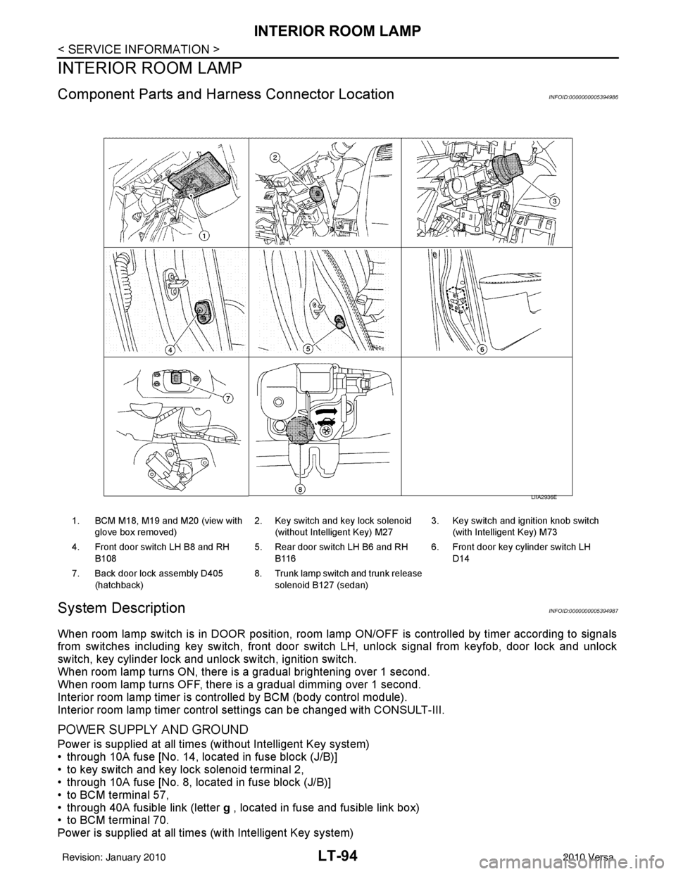
Component Parts and Harness Connector LocationINFOID:0000000005394986
System DescriptionINFOID:0000000005394987
When room lamp switch is in DOOR position, room lamp ON/OFF is controlled by timer according to signals
from switches including key switch, front door switch LH, unlock signal from keyfob, door lock and unlock
switch, key cylinder lock and unlock switch, ignition switch.
When room lamp turns ON, there is a gradual brightening over 1 second.
When room lamp turns OFF, there is a gradual dimming over 1 second.
Interior room lamp timer is controlled by BCM (body control module).
Interior room lamp timer control settings can be changed with CONSULT-III.
POWER SUPPLY AND GROUND
Power is supplied at all times (without Intelligent Key system)
• through 10A fuse [No. 14, located in fuse block (J/B)]
• to key switch and key lock solenoid terminal 2,
• through 10A fuse [No. 8, located in fuse block (J/B)]
• to BCM terminal 57,
• through 40A fusible link (letter g , located in fuse and fusible link box)
• to BCM terminal 70.
Power is supplied at all times (with Intelligent Key system)
1. BCM M18, M19 and M20 (view with
glove box removed) 2. Key switch and key lock solenoid
(without Intelligent Key) M27 3. Key switch and ignition knob switch
(with Intelligent Key) M73
4. Front door switch LH B8 and RH B108 5. Rear door switch LH B6 and RH
B116 6. Front door key cylinder switch LH
D14
7. Back door lock assembly D405 (hatchback) 8. Trunk lamp switch and trunk release
solenoid B127 (sedan)
LIIA2936E
Revision: January 20102010 Versa
Page 3090 of 3745

INTERIOR ROOM LAMPLT-95
< SERVICE INFORMATION >
C
DE
F
G H
I
J
L
M A
B
LT
N
O P
• through 10A fuse (No. 31, located in fuse and fusible link box)
• to key switch and ignition knob switch terminals 2 and 4,
• through 10A fuse [No. 8, located in fuse block (J/B)]
• to BCM terminal 57,
• through 40A fusible link (letter g , located in fuse and fusible link box)
• to BCM terminal 70.
When key is inserted in the key switch and key lock solenoid, power is supplied (without Intelligent Key sys-
tem)
• through key switch and key lock solenoid terminal 1
• to BCM terminal 37.
When key is inserted in the key switch and ignition knob switch, power is supplied (with Intelligent Key system)
• through key switch and ignition knob switch terminal 1
• to BCM terminal 37.
When ignition knob switch is pushed, power is supplied (with Intelligent Key system)
• through key switch and ignition knob switch terminal 3
• to Intelligent Key unit terminal 27.
With the ignition switch in the ON or START position, power is supplied
• through 10A fuse [No. 6, located in fuse block (J/B)]
• to BCM terminal 38.
Ground is supplied
• to BCM terminal 67
• through grounds M57 and M61.
When front door LH is opened, ground is supplied
• to BCM terminal 47
• through front door switch LH terminal 2
• through case ground of front door switch LH.
When front door RH is opened, ground is supplied
• to BCM terminal 12
• through front door switch RH terminal 2
• through case ground of front door switch RH.
When rear door LH is opened, ground is supplied
• to BCM terminal 48
• through rear door switch LH terminal 1
• through case ground of rear door switch LH.
When rear door RH is opened, ground is supplied
• to BCM terminal 13
• through rear door switch RH terminal 1
• through case ground of rear door switch RH.
When back door (hatchback) is opened, ground is supplied
• to BCM terminal 43
• through back door lock assembly (back door switch) terminal 3
• through back door lock assembly (back door switch) terminal 4
• through grounds B117, B132 and D402.
When trunk lid (sedan) is opened, ground is supplied
• to BCM terminal 42
• through trunk lamp switch and trunk release solenoid terminal 3
• through trunk lamp switch and trunk release solenoid terminal 1
• through grounds B117 and B132.
When front door LH is unlocked by front door key cylinder switch LH, the BCM receives a ground signal
• to BCM terminal 7
• through front door key cylinder switch LH terminal 3
• through front door key cylinder switch LH terminal 2
• through grounds M57 and M61.
When a signal, or combination of signals is received by BCM, ground is supplied
• to room lamp terminal 2
• through map lamp terminals 5 and 2 (with map lamp)
• through BCM terminal 63.
With power and ground supplied, the interior room lamp illuminates.
SWITCH OPERATION
When map lamp switch is ON (with map lamp), ground is supplied
• through grounds M57 and M61.
Revision: January 20102010 Versa
Page 3091 of 3745

LT-96
< SERVICE INFORMATION >
INTERIOR ROOM LAMP
• to map lamp terminal 1
Power is supplied
• through BCM terminal 56
• to map lamp terminal 4.
When interior room lamp switch is ON, ground is supplied
• to interior room lamp terminal 1
• through map lamp (with map lamp) terminal 7
• through map lamp (with map lamp) terminal 1
• through grounds M57 and M61.
Power is supplied
• through BCM terminal 56
• through map lamp (with map lamp) terminal 4
• through map lamp (with map lamp) terminal 6
• to room lamp terminal 3.
INTERIOR ROOM LAMP TIMER OPERATION
Without Intelligent Key System
When room lamp switch is in DOOR position, and when all conditions below are met, BCM performs timer
control (maximum 30 seconds) for room lamp ON/OFF.
In addition, when the interior room lamp turns ON or OFF there is gradual brightening or dimming over 1 sec-
ond.
Power is supplied
• through 10A fuse [No. 14, located in fuse block (J/B)]
• to key switch and key lock solenoid terminal 2.
When the key is removed from ignition key cylinder (key switch OFF), power will not be supplied to BCM termi-
nal 37.
When front door key cylinder switch LH is unlocked, ground is supplied
• to BCM terminal 7
• through front door key cylinder switch LH terminal 3
• through front door key cylinder switch LH terminal 2
• through grounds M57 and M61.
At the time that front door LH is opened, BCM detects that front door LH is unlocked. It determines that interior
room lamp timer operation condition is met, and turns the room lamp ON for 30 seconds.
When key is in ignition key cylinder (key switch ON),
Power is supplied
• through key switch and key lock solenoid terminal 1
• to BCM terminal 37.
When key is removed from key switch and key lock solenoid (key switch OFF), the power supply to BCM ter-
minal 37 is terminated. BCM detects that key has been removed, determines that interior room lamp timer
conditions are met, and turns the room lamp ON for 30 seconds.
When front door LH opens → closes, and the key is not inserted in the key switch and key lock solenoid (key
switch OFF), voltage at BCM terminal 47 changes between 0V (door open) → 12V (door closed). The BCM
determines that conditions for room lamp operation are met and turns the room lamp ON for 30 seconds.
Interior room lamp timer control is canceled under the following conditions:
• Front door LH is locked (locked by front door key cylinder switch LH, keyfob or door lock/unlock switch).
• Front door LH is opened (front door switch LH).
• Ignition switch ON.
With Intelligent Key System
When the room lamp switch is in DOOR position, and when all conditions below are met, BCM performs timer
control (maximum 30 second) for room lamp ON/OFF.
In addition, when interior room lamp turns ON or OFF there is gradual brightening or dimming over 1 second.
Power is supplied
• through 10A fuse (No. 31, located in fuse and fusible link box)
• to key switch and ignition knob switch terminals 2 and 4.
When key is removed from ignition key cylinder (key switch OFF), power will not be supplied to BCM terminal
37.
When the ignition knob switch is released, power will not be supplied to Intelligent Key unit terminal 27.
When front door key cylinder switch LH is unlocked, ground is supplied
• to BCM terminal 7
• through front door key cylinder switch LH terminal 3
Revision: January 20102010 Versa
Page 3105 of 3745

LT-110
< SERVICE INFORMATION >
ILLUMINATION
ILLUMINATION
System DescriptionINFOID:0000000005394998
The control of the illumination lamps operation is dependent upon the position of the lighting switch. When the
lighting switch is placed in the 1ST or 2ND position, the BCM (body con\
trol module) receives input signal
requesting the illumination lamps to illuminate. This i nput signal is communicated to IPDM E/R (intelligent
power distribution module engine room) across CAN communication lines. CPU (central processing unit)
located in the IPDM E/R controls the tail lamp relay coil. This relay, when energized, directs power to the illu-
mination lamps, which then illuminate.
Power is supplied at all times
• to ignition relay, located in IPDM E/R,
• to tail lamp relay, located in IPDM E/R,
• through 15A fuse (No. 52, located in IPDM E/R) and
• through 20A fuse (No. 53, located in IPDM E/R)
• to CPU located in IPDM E/R,
• through 40A fusible link (letter g, located in fuse and fusible link box)
• to BCM terminal 70, and
• through 10A fuse [No. 8, located in fuse block (J/B)]
• to BCM terminal 57.
With the ignition switch in the ON or START position, power is supplied
• to ignition relay, located in IPDM E/R, and
• through 10A fuse [No. 6, located in fuse block (J/B)]
• to BCM terminal 38.
With the ignition switch in the ACC or ON position, power is supplied
• through 10A fuse [No. 20, located in fuse block (J/B)]
• to BCM terminal 11.
Ground is supplied
• to BCM terminal 67
• through grounds M57 and M61
• to IPDM E/R terminals 39 and 59, and
• through grounds E15 and E24.
ILLUMINATION OPERATION BY LIGHTING SWITCH
With the lighting switch in the 1ST or 2ND position, BCM receives input signal requesting the illumination
lamps to illuminate. This input signal is communica ted to IPDM E/R across CAN communication lines. CPU
located in the IPDM E/R controls the tail lamp relay coil, which, when energized, directs power
• through 10A fuse (No. 37, located in IPDM E/R)
• through IPDM E/R terminal 29
• to illumination control switch terminal 1
• to VDC OFF switch terminal 3 (with VDC)
• to audio unit (with audio unit) or AV control unit (with premium audio system) terminal 9
• to front air control terminal 5
• to A/T shift selector terminal 3 (with 4-speed A/T)
• to CVT shift selector terminal 3 (with CVT)
• to hazard switch terminal 3
• to combination meter terminal 12
• to door mirror remote control switch terminal 16
• to combination switch (spiral cable) terminal 26 (with steering wheel audio control switches)
• to steering wheel audio control switches through combination switch (spiral cable) terminal 18 (with steering wheel audio control switches).
Ground is supplied
• to VDC OFF switch terminal 4 (with VDC)
• to illumination control switch terminal 3, and
• through grounds M57 and M61.
The illumination control switch controls illumination intensity by varying the ground to the following
• through illumination control switch terminal 2
• to audio unit (with audio unit) or AV control unit (with premium audio system) terminal 8
• to front air control terminal 6
• to A/T shift selector terminal 4 (with 4-speed A/T)
• to CVT shift selector terminal 3 (with CVT)
Revision: January 20102010 Versa