2010 NISSAN TIIDA fog light
[x] Cancel search: fog lightPage 2300 of 3745
![NISSAN TIIDA 2010 Service Repair Manual SERVICE DATA AND SPECIFICATIONS (SDS)EC-1035
< SERVICE INFORMATION > [MR18DE]
C
D
E
F
G H
I
J
K L
M A
EC
NP
O
SERVICE DATA AND SPECIFICATIONS (SDS)
Fuel PressureINFOID:0000000005532926
Idle Speed and NISSAN TIIDA 2010 Service Repair Manual SERVICE DATA AND SPECIFICATIONS (SDS)EC-1035
< SERVICE INFORMATION > [MR18DE]
C
D
E
F
G H
I
J
K L
M A
EC
NP
O
SERVICE DATA AND SPECIFICATIONS (SDS)
Fuel PressureINFOID:0000000005532926
Idle Speed and](/manual-img/5/57397/w960_57397-2299.png)
SERVICE DATA AND SPECIFICATIONS (SDS)EC-1035
< SERVICE INFORMATION > [MR18DE]
C
D
E
F
G H
I
J
K L
M A
EC
NP
O
SERVICE DATA AND SPECIFICATIONS (SDS)
Fuel PressureINFOID:0000000005532926
Idle Speed and Ignition TimingINFOID:0000000005532927
*: Under the following conditions:
• Air conditioner switch: OFF
• Electric load: OFF (Lights, heater fan & rear window defogger)
• Steering wheel: Kept in straight-ahead position
Calculated Load ValueINFOID:0000000005532928
Mass Air Flow SensorINFOID:0000000005532929
*: Engine is warmed up to normal operating temperature and running under no load.
Intake Air Temperature SensorINFOID:0000000005532930
Engine Coolant Temperature SensorINFOID:0000000005532931
Fuel pressure at idle
Approximately 350 kPa (3.57 kg/cm2, 51 psi)
Target idle speedA/T No load* (in P or N position)
700 ± 50 rpm
CVT No load* (In P or N position)
M/T No load* (in Neutral position)
Air conditioner: ON A/T In P or N position
850 rpm or more
CVT In P or N position
M/T In Neutral position
Ignition timing A/T In P or N position
13 ± 5 ° BTDC
CVT In P or N position
M/T In Neutral position
Calculated load value (Using CONSULT-III or GST)
At idle 10 - 35 %
At 2,500 rpm 10 - 35 %
Supply voltageBattery voltage (11 - 14 V )
Output voltage at idle 1.0 - 1.3* V
Mass air flow (Using CONSULT-III or GST) 1.0 - 4.0 g·m/sec at idle*
2.0 - 10.0 g·m/sec at 2,500 rpm*
Temperature [ °C ( °F)] Resistance (k Ω)
25 (77) 1.800 - 2.200
Temperature [°C ( °F)] Resistance (k Ω)
20 (68) 2.1 - 2.9
50 (122) 0.68 - 1.00
90 (194) 0.236 - 0.260
Revision: January 20102010 Versa
Page 2773 of 3745
GW-56
< SERVICE INFORMATION >
REAR WINDOW DEFOGGER
BCM Power Supply and Ground Circuit Inspection
INFOID:0000000005396777
Refer to BCS-16, "BCM Power Supply and Ground Circuit Inspection" .
Rear Window Defogger Swit ch Circuit InspectionINFOID:0000000005396778
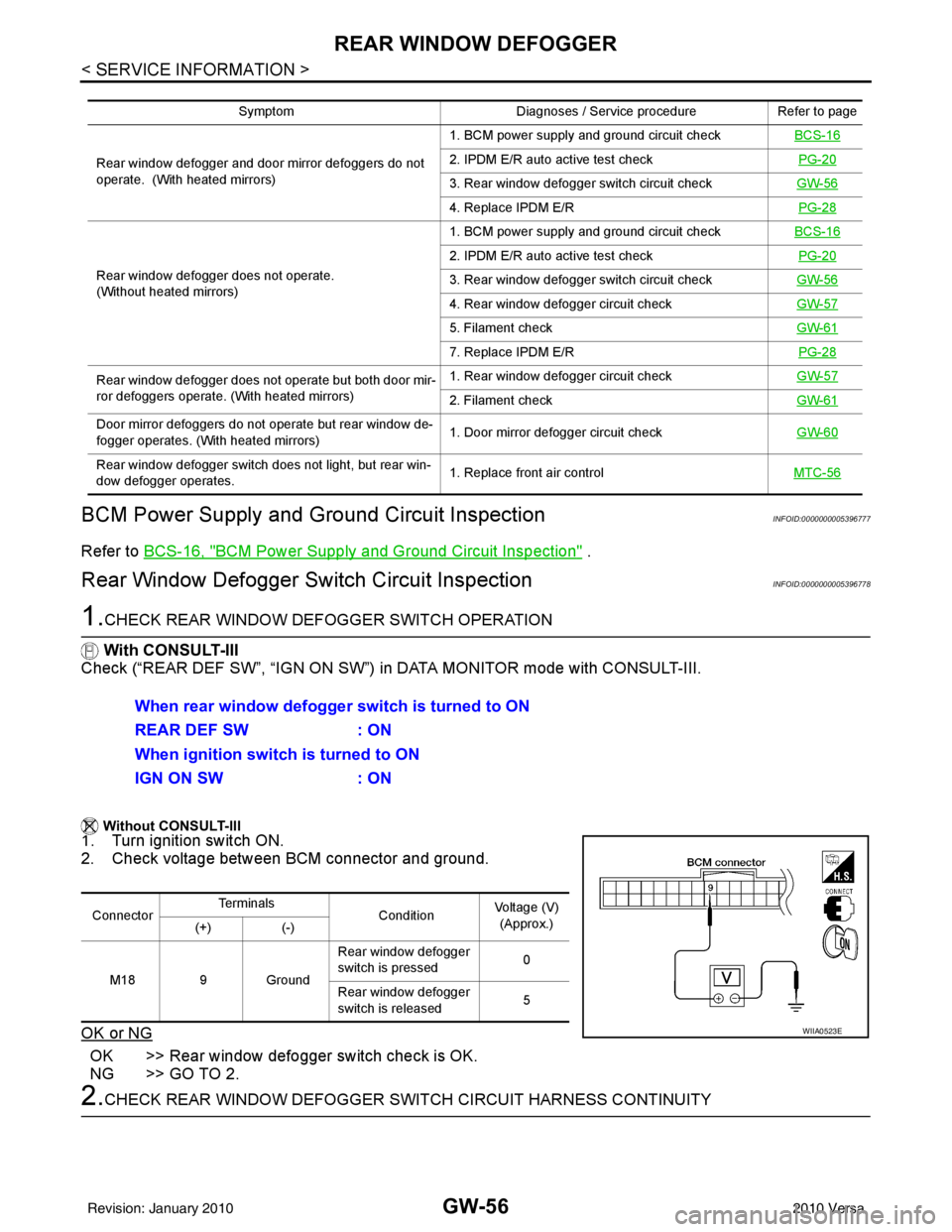
1.CHECK REAR WINDOW DEFOGGER SWITCH OPERATION
With CONSULT-III
Check (“REAR DEF SW”, “IGN ON SW”) in DATA MONITOR mode with CONSULT-III.
Without CONSULT-III
1. Turn ignition switch ON.
2. Check voltage between BCM connector and ground.
OK or NG
OK >> Rear window defogger switch check is OK.
NG >> GO TO 2.
2.CHECK REAR WINDOW DEFOGGER SWITCH CIRCUIT HARNESS CONTINUITY
Symptom Diagnoses / Service procedureRefer to page
Rear window defogger and door mirror defoggers do not
operate. (With heated mirrors) 1. BCM power supply and ground circuit check
BCS-16
2. IPDM E/R auto active test check PG-20
3. Rear window defogger switch circuit checkGW-56
4. Replace IPDM E/R PG-28
Rear window defogger does not operate.
(Without heated mirrors) 1. BCM power supply and ground circuit check
BCS-16
2. IPDM E/R auto active test check PG-20
3. Rear window defogger switch circuit checkGW-56
4. Rear window defogger circuit checkGW-57
5. Filament checkGW-61
7. Replace IPDM E/R PG-28
Rear window defogger does not operate but both door mir-
ror defoggers operate. (With heated mirrors) 1. Rear window defogger circuit check
GW-57
2. Filament checkGW-61
Door mirror defoggers do not operate but rear window de-
fogger operates. (With heated mirrors) 1. Door mirror defogger circuit check
GW-60
Rear window defogger switch does not light, but rear win-
dow defogger operates. 1. Replace front air control
MTC-56
When rear window defogger switch is turned to ON
REAR DEF SW: ON
When ignition switch is turned to ON
IGN ON SW : ON
ConnectorTe r m i n a l s
ConditionVoltage (V)
(Approx.)
(+) (-)
M18 9 Ground Rear window defogger
switch is pressed
0
Rear window defogger
switch is released 5
WIIA0523E
Revision: January 20102010 Versa
Page 2779 of 3745
GW-62
< SERVICE INFORMATION >
REAR WINDOW DEFOGGER
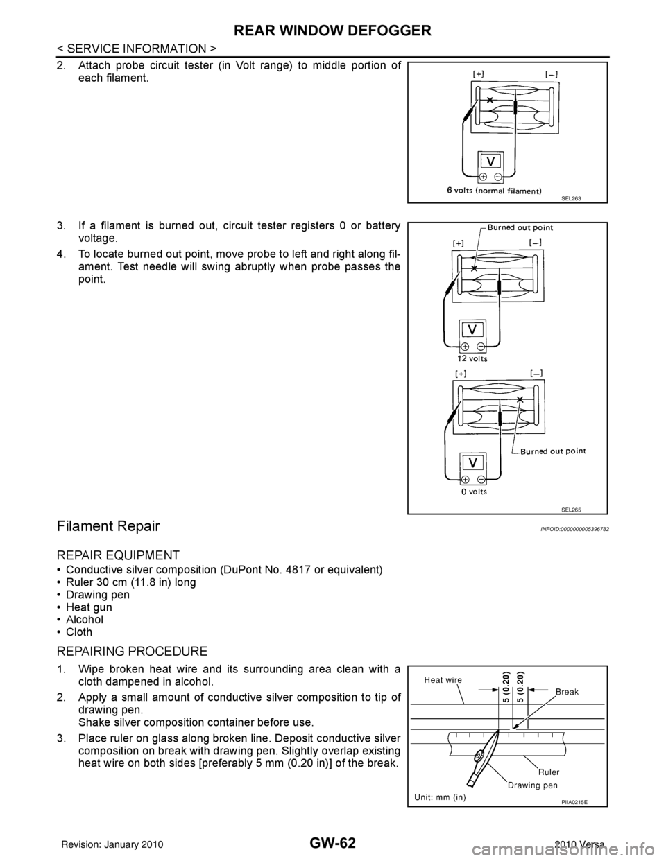
2. Attach probe circuit tester (in Volt range) to middle portion ofeach filament.
3. If a filament is burned out, circuit tester registers 0 or battery voltage.
4. To locate burned out point, move probe to left and right along fil- ament. Test needle will swing abruptly when probe passes the
point.
Filament RepairINFOID:0000000005396782
REPAIR EQUIPMENT
• Conductive silver composition (DuPont No. 4817 or equivalent)
• Ruler 30 cm (11.8 in) long
• Drawing pen
• Heat gun
• Alcohol
• Cloth
REPAIRING PROCEDURE
1. Wipe broken heat wire and its surrounding area clean with acloth dampened in alcohol.
2. Apply a small amount of conductive silver composition to tip of drawing pen.
Shake silver composition container before use.
3. Place ruler on glass along broken line. Deposit conductive silver composition on break with drawing pen. Slightly overlap existing
heat wire on both sides [preferably 5 mm (0.20 in)] of the break.
SEL263
SEL265
PIIA0215E
Revision: January 20102010 Versa
Page 2836 of 3745
![NISSAN TIIDA 2010 Service Repair Manual CAN COMMUNICATION SYSTEMLAN-27
< SERVICE INFORMATION > [CAN]
C
D
E
F
G H
I
J
L
M A
B
LAN
N
O P
CAN Communication Signal ChartINFOID:0000000005395135
Refer to LAN-16, "How to Use CAN Communication Sig NISSAN TIIDA 2010 Service Repair Manual CAN COMMUNICATION SYSTEMLAN-27
< SERVICE INFORMATION > [CAN]
C
D
E
F
G H
I
J
L
M A
B
LAN
N
O P
CAN Communication Signal ChartINFOID:0000000005395135
Refer to LAN-16, "How to Use CAN Communication Sig](/manual-img/5/57397/w960_57397-2835.png)
CAN COMMUNICATION SYSTEMLAN-27
< SERVICE INFORMATION > [CAN]
C
D
E
F
G H
I
J
L
M A
B
LAN
N
O P
CAN Communication Signal ChartINFOID:0000000005395135
Refer to LAN-16, "How to Use CAN Communication Signal Chart" for how to use CAN communication signal
chart.
NOTE:
Refer to LAN-22, "
Abbreviation List" for the abbreviations of the connecting units.
T: Transmit R: Receive
Signal name/Connecting unitECM
BCM
EPS
I-KEY M&A
STRG ABS
TCM
*1
TCM
*2
IPDM-E
A/C compressor request signal T R
Accelerator pedal position signal T
R
*3RR
ASCD CRUISE lamp signal T R
ASCD SET lamp signal T R
Closed throttle position signal T R R
Cooling fan motor operation signal T R
Engine coolant temperature signal TR
Engine speed signal TR
R
*3R
Engine status signal T R R R
Fuel consumption monitor signal T R
Malfunction indicator lamp signal TR
Wide open throttle position signal T R R
A/C switch signal R T
Blower fan motor switch signal R T
Buzzer output signal TR
TR
Day time running light request signal
*4TR
Door lock/unlock status signal TR
Door switch signal TR R R
Front wiper request signal T R
High beam request signal TR R
Horn chirp signal T R
Ignition switch signal T R
Low beam request signal T R
Position lights request signal TR R
Rear window defogger switch signal T R
Sleep/wake up signal TRR
R
RT
Theft warning horn request signal T R
Tire pressure signal
*5TR
Trunk open/close status signal TR
Turn indicator signal TR
EPS operation signal TR
EPS warning lamp signal TR
Door lock/unlock/trunk open request signal RT
Hazard request signal RT
Ignition knob switch signal RT
Revision: January 20102010 Versa
Page 2996 of 3745

LT-1
ELECTRICAL
C
DE
F
G H
I
J
L
M
SECTION LT
A
B
LT
N
O P
CONTENTS
LIGHTING SYSTEM
SERVICE INFORMATION .. ..........................3
PRECAUTIONS .............................................. .....3
Precaution for Supplemental Restraint System
(SRS) "AIR BAG" and "SEAT BELT PRE-TEN-
SIONER" ............................................................. ......
3
Precaution Necessary for Steering Wheel Rota-
tion After Battery Disconnect ............................... ......
3
PREPARATION ...................................................5
Special Service Tool ........................................... ......5
HEADLAMP (FOR USA) .....................................6
Component Parts and Harness Connector Loca-
tion ...................................................................... ......
6
System Description ...................................................6
CAN COMMUNICATION SYSTEM DESCRIP-
TION .................................................................... ......
7
Schematic .................................................................8
Wiring Diagram .........................................................9
Terminal and Reference Value for BCM .................12
Terminal and Reference Value for IPDM E/R .........12
How to Perform Trouble Diagnosis .........................13
Preliminary Check ...................................................13
CONSULT-III Function (BCM) .................................13
CONSULT-III Function (IPDM E/R) .........................14
Headlamp High Beam Does Not Illuminate (Both
Sides) .................................................................. ....
16
Headlamp High Beam Does Not Illuminate (One
Side) .................................................................... ....
18
High Beam Indicator Lamp Does Not Illuminate .....19
Headlamp Low Beam Does Not Illuminate (Both
Sides) .................................................................. ....
20
Headlamp Low Beam Does Not Illuminate (One
Side) .................................................................... ....
22
Headlamps Do Not Turn OFF .................................23
Aiming Adjustment ..................................................24
Bulb Replacement ...................................................25
Removal and Installation .........................................26
Disassembly and Assembly ................................ ....26
HEADLAMP (FOR CANADA) - DAYTIME
LIGHT SYSTEM - ..............................................
28
Component Parts and Harness Connector Loca-
tion ....................................................................... ....
28
System Description ..................................................28
CAN Communication System Description ...............30
Schematic ................................................................31
Wiring Diagram - DTRL - .........................................32
Terminal and Reference Value for BCM ..................35
Terminal and Reference Value for IPDM E/R ...... ....35
How to Perform Trouble Diagnosis ..........................36
Preliminary Check ...................................................36
CONSULT-III Function (BCM) .................................36
CONSULT-III Function (IPDM E/R) ..................... ....36
Daytime Light Control Does Not Operate Properly
(High Beam Headlamps Operate Properly) .............
36
Aiming Adjustment ...................................................38
Bulb Replacement ...................................................39
Removal and Installation .........................................40
Disassembly and Assembly .....................................40
FRONT FOG LAMP ..........................................42
Component Parts and Harness Connector Loca-
tion ...........................................................................
42
System Description ..................................................42
CAN Communication System Description ...............43
Wiring Diagram - F/FOG - .......................................44
Terminal and Reference Value for BCM ..................45
Terminal and Reference Value for IPDM E/R ...... ....45
How to Proceed with Trouble Diagnosis ..................46
Preliminary Check ............................................... ....46
CONSULT-III Function (BCM) .................................46
CONSULT-III Function (IPDM E/R) ..................... ....46
Front Fog lamps Do Not Illuminate (Both Sides) .....46
Front Fog Lamp Does Not Illuminate (One Side) ....48
Aiming Adjustment ...................................................49
Bulb Replacement ...................................................50
Removal and Installation .........................................50
TURN SIGNAL AND HAZARD WARNING
LAMPS ..............................................................
51
Revision: January 20102010 Versa
Page 3011 of 3745
LT-16
< SERVICE INFORMATION >
HEADLAMP (FOR USA)
*1 Perform monitoring of IPDM E/R data with the ignition switch ON. When the ignition switch is in ACC position, display may not be cor-
rect.
*2 This item is displayed, but does not function.
CAN DIAG SUPPORT MNTR
Refer to LAN-9, "Description" .
ACTIVE TEST
Display Item List
Headlamp High Beam Does No t Illuminate (Both Sides)INFOID:0000000005394886
1.CHECK COMBINATION SWITCH INPUT SIGNAL
With CONSULT-III
1. Select “BCM” on CONSULT-III. Select “HEAD LAMP” on “SELECT TEST ITEM” screen.
2. Select “DATA MONITOR” on “SELECT DIAG MODE” screen. Make sure that “HI BEAM SW” turns ON-
OFF linked with operation of lighting switch.
Without CONSULT-III
Refer to LT-66, "
Combination Switch Inspection" .
OK or NG
OK >> GO TO 2.
NG >> Check combination switch (lighting switch). Refer to LT-66, "
Combination Switch Inspection" .
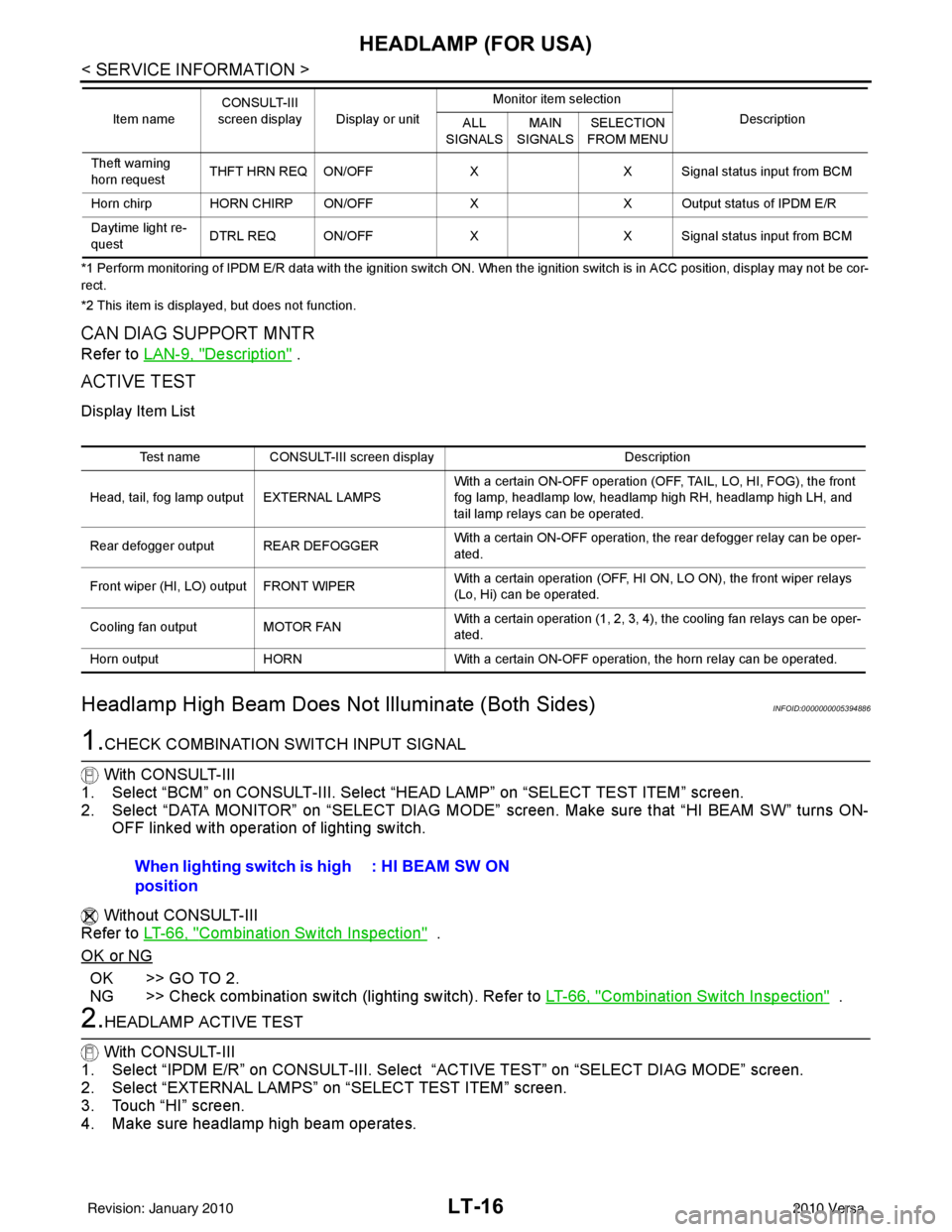
2.HEADLAMP ACTIVE TEST
With CONSULT-III
1. Select “IPDM E/R” on CONSULT-III. Select “ACTIVE TEST” on “SELECT DIAG MODE” screen.
2. Select “EXTERNAL LAMPS” on “SELECT TEST ITEM” screen.
3. Touch “HI” screen.
4. Make sure headlamp high beam operates.
Theft warning
horn request THFT HRN REQ ON/OFF
XX Signal status input from BCM
Horn chirp HORN CHIRP ON/OFF XX Output status of IPDM E/R
Daytime light re-
quest DTRL REQ ON/OFF
XX Signal status input from BCM
Item name
CONSULT-III
screen display Display or unit Monitor item selection
Description
ALL
SIGNALS MAIN
SIGNALS SELECTION
FROM MENU
Test name CONSULT-III screen display Description
Head, tail, fog lamp output EXTERNAL LAMPS With a certain ON-OFF operation (OFF, TAIL, LO, HI, FOG), the front
fog lamp, headlamp low, headlamp high RH, headlamp high LH, and
tail lamp relays can be operated.
Rear defogger output REAR DEFOGGER With a certain ON-OFF operation, the rear defogger relay can be oper-
ated.
Front wiper (HI, LO) output FRONT WIPER With a certain operation (OFF, HI ON, LO ON), the front wiper relays
(Lo, Hi) can be operated.
Cooling fan output MOTOR FAN With a certain operation (1, 2, 3, 4), the cooling fan relays can be oper-
ated.
Horn output HORN With a certain ON-OFF operation, the horn relay can be operated.
When lighting switch is high
position : HI BEAM SW ON
Revision: January 20102010 Versa
Page 3037 of 3745
LT-42
< SERVICE INFORMATION >
FRONT FOG LAMP
FRONT FOG LAMP
Component Parts and Harness Connector LocationINFOID:0000000005394912
System DescriptionINFOID:0000000005394913
The front fog lamps are controlled by lighting switch inputs to the BCM (body control module). The lighting
switch must be in the 1ST or 2ND position with t he high beams OFF before the BCM will request the IPDM E/
R (intelligent power distribution module engine room) to turn the front fog lamps on. The BCM requests the
front fog lamps over the CAN communication lines to the IPDM E/R. The CPU (central processing unit) of the
IPDM E/R controls the front fog lamp relay coil ground. When energized, the relay directs power to the front
fog lamps.
OUTLINE
Power is supplied at all times:
• to front fog lamp relay (located in IPDM E/R),
• to ignition relay (located in IPDM E/R),
• through 15A fuse (No. 52, located in IPDM E/R) and
• through 20A fuse (No. 53, located in IPDM E/R)
• to CPU located in IPDM E/R,
• through 40A fusible link (letter g , located in the fuse and fusible link box)
• to BCM terminal 70,
• through 10A fuse [No. 8, located in fuse block (J/B)]
• to BCM terminal 57,
• through 10A fuse [No. 13, located in fuse block (J/B)]
• to combination meter terminal 27.
With the ignition switch in the ON or START position, power is supplied:
• to ignition relay (located in IPDM E/R),
• through 10A fuse [No. 6, located in fuse block (J/B)]
• to BCM terminal 38.
With the ignition switch in the ACC or ON position, power is supplied
• through 10A fuse [No. 20, located in fuse block (J/B)]
• to BCM terminal 11.
Ground is supplied
• to BCM terminal 67
• through grounds M57 and M61,
• to IPDM E/R terminals 39 and 59
• through grounds E15 and E24.
FOG LAMP OPERATION
The front fog lamp switch is built into the lighting s witch. The lighting switch must be in 1ST position or 2ND
position and front fog lamp switch must be ON position fo r front fog lamp operation. The fog lamp will not oper-
ate with the high beam headlamps ON.
When the front fog lamp switch is in the ON positi on, the BCM sends a request, via the CAN communication
lines, to the CPU of the IPDM E/R to ground the coil side of the front fog lamp relay. The front fog lamp relay
then directs power
• through 15A fuse (No. 56, located in IPDM E/R)
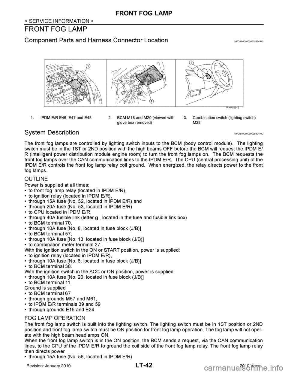
1. IPDM E/R E46, E47 and E48 2. BCM M18 and M20 (viewed with
glove box removed)3. Combination switch (lighting switch)
M28
WKIA5554E
Revision: January 20102010 Versa
Page 3041 of 3745
LT-46
< SERVICE INFORMATION >
FRONT FOG LAMP
How to Proceed with Trouble Diagnosis
INFOID:0000000005394918
1. Confirm the symptom or customer complaint.
2. Understand operation description and function description. Refer to LT-42, "
System Description" .
3. Perform the Preliminary Check. Refer to LT-46, "
Preliminary Check" .
4. Check symptom and repair or replace the cause of the malfunction.
5. Do the front fog lamps operate normally? If YES, GO TO 6. If NO, GO TO 4.
6. INSPECTION END.
Preliminary CheckINFOID:0000000005394919
CHECK POWER SUPPLY AND GROUND CIRCUIT FOR BCM
Refer to BCS-16, "BCM Power Supply and Ground Circuit Inspection" .
CHECK POWER SUPPLY AND GROUND CIRCUIT FOR IPDM E/R
Refer to PG-27, "IPDM E/R Power/Ground Circuit Inspection" .
CONSULT-III Function (BCM)INFOID:0000000005394920
Refer to LT-13, "CONSULT-III Function (BCM)" .
CONSULT-III Function (IPDM E/R)INFOID:0000000005394921
Refer to LT-14, "CONSULT-III Function (IPDM E/R)" .
Front Fog lamps Do Not Illuminate (Both Sides)INFOID:0000000005394922
1.INSPECT FOG LAMP FUSE
Inspect fog lamp 15A fuse No. 56 in IPDM E/R.
OK or NG
OK >> GO TO 2.
NG >> Repair harness.
2.CHECK COMBINATION SWITCH INPUT SIGNAL
1. Select “BCM” on CONSULT-III. Select “HEAD LAMP” on “SELECT TEST ITEM” screen.
2. Select “DATA MONITOR” on “SELECT DIAG MODE” screen. Make sure that “FR FOG SW” turns ON-
OFF linked with operation of fog lamp switch.
With CONSULT-III
Select “BCM” on CONSULT-III. With “HEAD LAMP” dat a monitor, make sure “FR FOG SW” turns ON-OFF
linked with operation of front fog lamp switch.
Without CONSULT-III
Refer to LT-66, "
Combination Switch Inspection" .
OK or NG
OK >> GO TO 3.
NG >> Check combination switch (lighting switch). Refer to LT-66, "
Combination Switch Inspection" .
3.FOG LAMP ACTIVE TEST
With CONSULT-III
1. Select “IPDM E/R” on CONSULT-III. Select “ACTIVE TEST” on “SELECT DIAG MODE” screen.
2. Select “EXTERNAL LAMPS” on “SELECT TEST ITEM” screen.
3. Touch “FOG” screen.
4. Make sure front fog lamp operates.
Without CONSULT-III When fog lamp switch is ON : FR FOG SW ON
Front fog lamp should operate.
Revision: January 20102010 Versa