2010 NISSAN TIIDA BCM
[x] Cancel search: BCMPage 3718 of 3745

FRONT WIPER AND WASHER SYSTEMWW-13
< SERVICE INFORMATION >
C
DE
F
G H
I
J
L
M A
B
WW
N
O P
ACTIVE TEST
Display Item List
CONSULT-III Function (IPDM E/R)INFOID:0000000005395064
CONSULT-III can display each diagnostic item using the diagnostic test modes shown following.
DATA MONITOR
All Signals, Main Signals, Selection From Menu
NOTE:
Perform monitoring of IPDM E/R data with ignition switch ON. When ignition switch is at ACC, the display may
not be correct.
ACTIVE TEST
FR WIPER INT “ON/OFF” Displays “FRONT WIPER INT (ON)/Other (OFF)” status as judged from wiper switch signal.
FR WASHER SW “ON/OFF” Displays “FRONT WASHER Switch
(ON)/Other (OFF)” status as judged from wiper switch sig-
nal.
INT VOLUME “1 - 7” Displays intermittent operation dial position setting (1 - 7) as judged from wiper switch signal.
FR WIPER STOP “ON/OFF” Displays “Stopped (ON)/Operati ng (OFF)” status as judged from auto-stop signal.
VEHICLE SPEED “km/h” Displays vehicle speed stat us as judged from vehicle speed signal.
RR WIPER ON “ON/OFF” Displays “REAR WIPER (ON)/Other (O FF)” status as judged from wiper switch signal.
RR WIPER INT “ON/OFF” Displays “REAR WIPER INT (ON)/Other (OFF)” status as judged from wiper switch signal.
RR WASHER SW “ON/OFF” Displays “FRONT WASHER Switch
(ON)/Other (OFF)” status as judged from wiper switch sig-
nal.
RR WIPER STOP “ON/OFF” Displays “Stopp ed (ON)/Operating (OFF)” status as judged from auto-stop switch 1.
RR WIPER STP2 “ON/OFF” Displays “Stopp ed (ON)/Operating (OFF)” status as judged from auto-stop switch 2.
Monitor item
Contents
Test item Display on CONSULT-III screen Description
Front wiper output FR WIPERFront LO wiper can be operated by any ON-OFF operation.
Rear wiper output RR WIPERRear wiper can be operated by any ON-OFF operation.
IPDM E/R diagnostic Mode Description
SELF DIAGNOSTIC RESULT Displays IPDM E/R self-diagnosis results.
DATA MONITOR Displays IPDM E/R input/output data in real time.
CAN DIAG SUPPORT MNTR The result of transmit/receive diagnosis of CAN communication can be read. ACTIVE TEST Operation of electrical loads can be checked by sending drive signal to them.
ALL SIGNALS Monitors all items.
MAIN SIGNALS Monitor the predetermined item.
SELECTION FROM MENU Selects items and monitors them.
Item name CONSULT-III
screen display Display or unit Monitor item selection
Description
ALL
SIGNALS MAIN
SIGNALS SELECTION
FROM MENU
FR wiper request FR WIP REQ STOP/1LOW/
LOW/HI×× ×
Signal status input from BCM
Wiper auto stop WIP AUTO STOP ACT P/STOP P ×× ×Output status of IPDM E/R
Wiper protection WIP PROT OFF/BLOCK ×× ×Control status of IPDM E/R
Revision: January 20102010 Versa
Page 3719 of 3745
WW-14
< SERVICE INFORMATION >
FRONT WIPER AND WASHER SYSTEM
Front Wiper Does Not Operate
INFOID:0000000005395065
CAUTION:
• During IPDM E/R fail-safe control, fr ont wipers may not operate. Refer to PG-17, "
System Descrip-
tion" in “PG IPDM E/R” to make sure that it is not in fail-safe status.
1.ACTIVE TEST
With CONSULT-lIl
1. Select “IPDM E/R” on CONSULT-III, and sele ct “ACTIVE TEST” on “SELECT DIAG MODE” screen.
2. Select “FRONT WIPER” on “SELECT TEST ITEM” screen.
3. Touch “LO” or “HI” screen.
Without CONSULT-lIl
Start up auto active test. Refer to PG-20, "
Auto Active Test" .
Does front wiper operate normally?
YES >> GO TO 2.
NO >> GO TO 4.
2.CHECK CIRCUIT BETWEEN COMB INATION SWITCH AND BCM
With CONSULT-llI
1. Select “BCM” on CONSULT-III, and sele ct “WIPER” on “SELECT TEST ITEM” screen.
2. Select “DATA MONITOR” on “SELECT DIAG MODE ” screen. Make sure that “FR WIPER INT”, “FR
WIPER LOW”, and “FR WIPER HI” turn ON-OFF according to wiper switch operation.
Without CONSULT-lIl
Refer to LT-66, "
Combination Switch Inspection" .
OK or NG
OK >> GO TO 3.
NG >> Check combination switch (wiper switch). Refer to LT-66, "
Combination Switch Inspection" .
3.CHECK CIRCUIT BETWEEN IPDM E/R AND BCM
Select “BCM” on CONSULT-III, and perform self-diagnosis for “BCM”.
Displayed self
-diagnosis results
NO DTC>>Replace BCM. Refer to BCS-19, "Removal and Installation of BCM" .
CAN COMM CIRCUIT>>Check CAN communi cation line of BCM. Refer to BCS-18, "
CAN Communication
Inspection Using CONSULT-III (Self-Diagnosis)" .
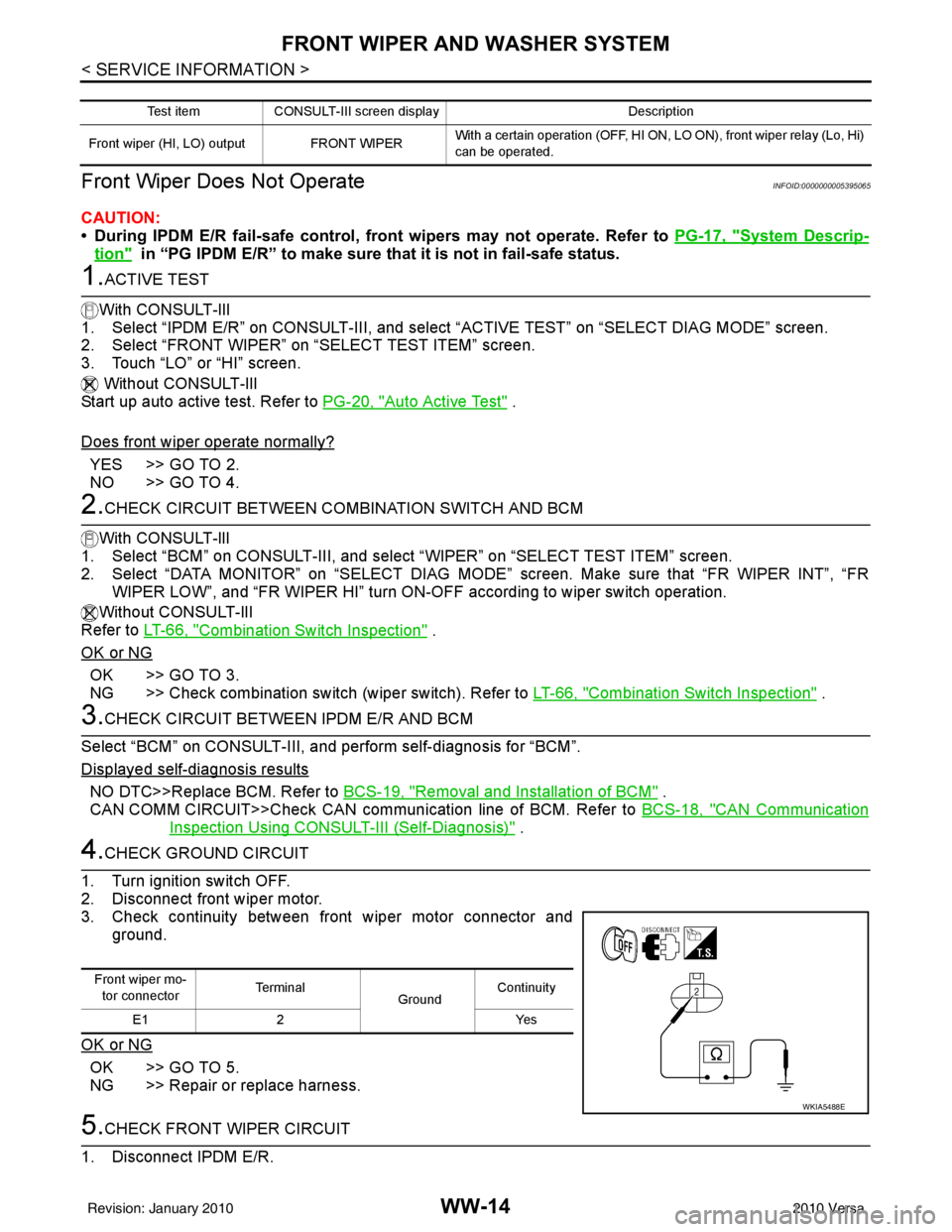
4.CHECK GROUND CIRCUIT
1. Turn ignition switch OFF.
2. Disconnect front wiper motor.
3. Check continuity between front wiper motor connector and ground.
OK or NG
OK >> GO TO 5.
NG >> Repair or replace harness.
5.CHECK FRONT WIPER CIRCUIT
1. Disconnect IPDM E/R.
Test item CONSULT-III screen display Description
Front wiper (HI, LO) output FRONT WIPER With a certain operation (OFF, HI ON,
LO ON), front wiper relay (Lo, Hi)
can be operated.
Front wiper mo- tor connector Te r m i n a l
GroundContinuity
E1 2 Yes
WKIA5488E
Revision: January 20102010 Versa
Page 3724 of 3745
FRONT WIPER AND WASHER SYSTEMWW-19
< SERVICE INFORMATION >
C
DE
F
G H
I
J
L
M A
B
WW
N
O P
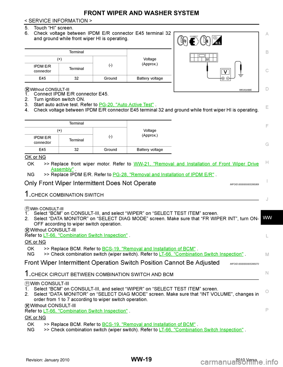
5. Touch “HI” screen.
6. Check voltage between IPDM E/R connector E45 terminal 32 and ground while front wiper HI is operating.
Without CONSULT-lIl
1. Connect IPDM E/R connector E45.
2. Turn ignition switch ON.
3. Start auto active test. Refer to PG-20, "
Auto Active Test" .
4. Check voltage between IPDM E/R connector E45 terminal 32 and ground while front wiper HI is operating.
OK or NG
OK >> Replace front wiper motor. Refer to WW-21, "Removal and Installation of Front Wiper Drive
Assembly" .
NG >> Replace IPDM E/R. Refer to PG-28, "
Removal and Installation of IPDM E/R" .
Only Front Wiper Intermittent Does Not OperateINFOID:0000000005395069
1.CHECK COMBINATION SWITCH
With CONSULT-lIl1. Select “BCM” on CONSULT-III, and sele ct “WIPER” on “SELECT TEST ITEM” screen.
2. Select “DATA MONITOR” on “SELECT DIAG MODE” sc reen. Make sure that “FR WIPER INT”, turn ON-
OFF according to wiper switch operation.
Without CONSULT-Ill
Refer to LT-66, "
Combination Switch Inspection" .
OK or NG
OK >> Replace BCM. Refer to BCS-19, "Removal and Installation of BCM" .
NG >> Check combination switch (wiper switch). Refer to LT-66, "
Combination Switch Inspection" .
Front Wiper Intermittent Operation Switch Position Cannot Be AdjustedINFOID:0000000005395070
1.CHECK CIRCUIT BETWEEN COMB INATION SWITCH AND BCM
With CONSULT-lIl
1. Select “BCM” on CONSULT-III, and select “WIPER” on “SELECT TEST ITEM” screen.
2. Select “DATA MONITOR” on “SELECT DIAG MODE” screen. Make sure that “INT VOLUME”, changes in
order from 1 to 7 according to wiper switch operation.
Without CONSULT-Ill
Refer to LT-66, "
Combination Switch Inspection" .
OK or NG
OK >> Replace BCM. Refer to BCS-19, "Removal and Installation of BCM" .
NG >> Check combination switch (wiper switch). Refer to LT-66, "
Combination Switch Inspection" .
Te r m i n a l
Vo l ta g e
(Approx.)
(+)
(-)
IPDM E/R
connector Te r m i n a l
E45 32Ground Battery voltage
Te r m i n a l Vo l ta g e
(Approx.)
(+)
(-)
IPDM E/R
connector Te r m i n a l
E45 32Ground Battery voltage
WKIA5499E
Revision: January 20102010 Versa
Page 3725 of 3745
WW-20
< SERVICE INFORMATION >
FRONT WIPER AND WASHER SYSTEM
Wiper Does Not Wipe Wh en Front Washer Operates
INFOID:0000000005395071
1.CHECK CIRCUIT BETWEEN COMB INATION SWITCH AND BCM
With CONSULT-lIl
1. Select “BCM” on CONSULT-III, and sele ct “WIPER” on “SELECT TEST ITEM” screen.
2. Select “DATA MONITOR” on “SELECT DIAG MODE” screen. Make sure that “FR WASHER SW” turn ON-
OFF according to front wiper switch operation.
Without CONSULT-Ill
Refer to LT-66, "
Combination Switch Inspection" .
OK or NG
OK >> Replace BCM. Refer to BCS-19, "Removal and Installation of BCM" .
NG >> Check combination switch (wiper switch). Refer to LT-66, "
Combination Switch Inspection" .
Front Wiper Does Not StopINFOID:0000000005395072
1.CHECK CIRCUIT BETWEEN COMBINATION SWITCH AND BCM
With CONSULT-lIl
1. Select “BCM” on CONSULT-III, and sele ct “WIPER” on “SELECT TEST ITEM” screen.
2. Select “DATA MONITOR” on “SELECT DIAG MODE ” screen. Make sure that “FR WIPER INT”, “FR
WIPER LOW”, “FR WIPER HI”, and “FR WASHER SW” turn ON-OFF according to front wiper switch
operation.
Without CONSULT-Ill
Refer to LT-66, "
Combination Switch Inspection" .
OK or NG
OK >> Replace IPDM E/R. Refer to PG-27, "IPDM E/R Power/Ground Circuit Inspection" .
NG >> Check combination switch (wiper switch). Refer to LT-66, "
Combination Switch Inspection" .
Removal and Installation of Front Wiper ArmsINFOID:0000000005395073
REMOVAL
1. Turn wiper switch on to operate wiper motor, and then turn wiper switch off (auto stop).
2. Open hood, remove wiper arm caps, and remove wiper arm nuts.
3. Raise wiper arm, and remove wiper arm from the vehicle.
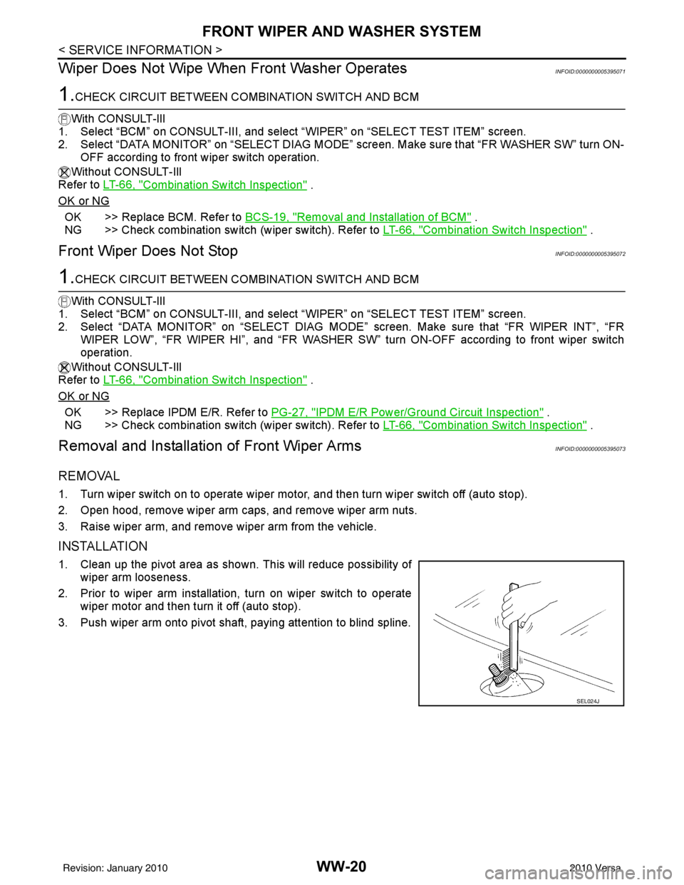
INSTALLATION
1. Clean up the pivot area as shown. This will reduce possibility of
wiper arm looseness.
2. Prior to wiper arm installation, turn on wiper switch to operate wiper motor and then turn it off (auto stop).
3. Push wiper arm onto pivot shaft, paying attention to blind spline.
SEL024J
Revision: January 20102010 Versa
Page 3731 of 3745
WW-26
< SERVICE INFORMATION >
REAR WIPER AND WASHER SYSTEM
REAR WIPER AND WASHER SYSTEM
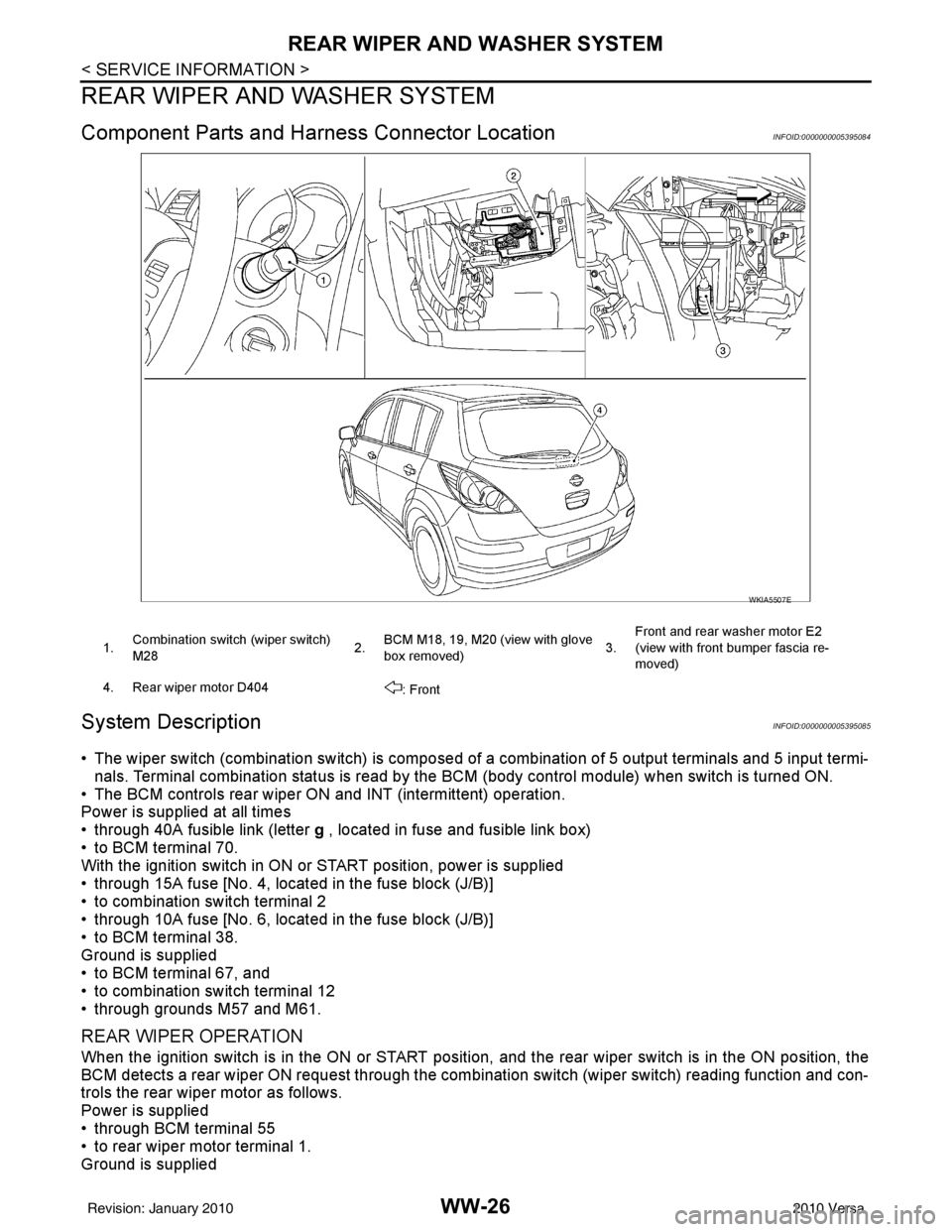
Component Parts and Harness Connector LocationINFOID:0000000005395084
System DescriptionINFOID:0000000005395085
• The wiper switch (combination switch) is composed of a combination of 5 output terminals and 5 input termi-
nals. Terminal combination status is read by the BC M (body control module) when switch is turned ON.
• The BCM controls rear wiper ON and INT (intermittent) operation.
Power is supplied at all times
• through 40A fusible link (letter g , located in fuse and fusible link box)
• to BCM terminal 70.
With the ignition switch in ON or START position, power is supplied
• through 15A fuse [No. 4, located in the fuse block (J/B)]
• to combination switch terminal 2
• through 10A fuse [No. 6, located in the fuse block (J/B)]
• to BCM terminal 38.
Ground is supplied
• to BCM terminal 67, and
• to combination switch terminal 12
• through grounds M57 and M61.
REAR WIPER OPERATION
When the ignition switch is in the ON or START position, and the rear wiper switch is in the ON position, the
BCM detects a rear wiper ON request through the combination switch (wiper switch) reading function and con-
trols the rear wiper motor as follows.
Power is supplied
• through BCM terminal 55
• to rear wiper motor terminal 1.
Ground is supplied
WKIA5507E
1. Combination switch (wiper switch)
M28 2.BCM M18, 19, M20 (view with glove
box removed) 3.Front and rear washer motor E2
(view with front bumper fascia re-
moved)
4. Rear wiper motor D404 : Front
Revision: January 20102010 Versa
Page 3732 of 3745
REAR WIPER AND WASHER SYSTEMWW-27
< SERVICE INFORMATION >
C
DE
F
G H
I
J
L
M A
B
WW
N
O P
• to rear wiper motor terminal 3
• through grounds B117, B132 and D402.
With power and ground supplied, the rear wiper motor operates.
INTERMITTENT OPERATION
The rear wiper motor operates the wiper arm at low speed approximately every 7 seconds.
When the wiper switch is in the rear wiper INT positi on, the BCM detects a rear wiper INT request through the
combination switch (wiper switch) reading function.
When BCM operates rear wiper motor, power is supplied
• through BCM terminal 55
• to rear wiper motor terminal 1.
Ground is supplied
• to rear wiper motor terminal 3
• through grounds B117, B132 and D402.
With power and ground supplied, the rear wiper operates in intermittent mode.
AUTO STOP OPERATION
When the rear wiper arm is not located at the base of the rear window, and the rear wiper switch is turned
OFF, the rear wiper motor will continue to operate until the rear wiper arm is at the base of the rear window.
When the rear wiper arm reaches the base, r ear wiper motor terminals 2 and 1 are connected.
Ground is supplied
• to BCM terminal 44
• through rear wiper motor terminal 2, and
• through rear wiper motor terminal 3, and
• through grounds B117, B132 and D402.
REAR WASHER OPERATION
When the ignition switch is in the ON or START positi on, and the front and rear washer switches are OFF, the
front and rear washer motor is supplied power
• through 15A fuse [No. 4, located in the fuse block (J/B)]
• to combination switch (wiper switch) terminal 14
• through combination switch (wiper switch) terminal 11
• to front and rear washer motor terminal 2.
When the rear wiper switch is in rear washer positi on, the BCM detects a rear washer signal by BCM wiper
switch reading function. Combination switch ground is supplied
• to front and rear washer motor terminal 1
• through combination switch (wiper switch) terminal 13, and
• through combination switch (wiper switch) terminal 12
• through grounds M57 and M61.
With ground supplied, the front and rear washer motor is operated in the rear direction.
When the BCM detects that the rear washer motor has operated for 0.4 seconds or longer, BCM operates the
rear wiper motor.
When the BCM detects that the rear washer switch is in OFF, the rear wiper motor cycles approximately 3
times and then stops.
If the rear washer is operated with the rear wiper switch in the INT position, normal rear wiper operation will
take over. Once the rear washer switch is re leased the rear wiper will return to INT operation.
BCM Combination Switch Reading Function
Refer to BCS-4, "System Description" .
Revision: January 20102010 Versa
Page 3735 of 3745
WW-30
< SERVICE INFORMATION >
REAR WIPER AND WASHER SYSTEM
Terminal and Reference Value for BCM
INFOID:0000000005395087
Refer to BCS-12, "Terminal and Reference Value for BCM" .
How to Proceed with Trouble DiagnosisINFOID:0000000005395088
1. Confirm the symptoms and customer complaint.
2. Understand operation description and function description. Refer to WW-26, "
System Description" .
3. Perform the Preliminary Check. Refer to WW-30, "
Preliminary Check" .
4. Check symptom and repair or replace the cause of malfunction.
5. Does the rear wiper operate normally? If YES: GO TO 6. If NO: GO TO 4.
6. Inspection End.
Preliminary CheckINFOID:0000000005395089
CHECK POWER SUPPLY AND GROUND CIRCUIT FOR BCM
Refer to BCS-16, "BCM Power Supply and Ground Circuit Inspection" .
CONSULT-III Function (BCM)INFOID:0000000005395090
Refer to WW-12, "CONSULT-III Function (BCM)" .
Rear Wiper Does Not OperateINFOID:0000000005395091
1.REAR WIPER ACTIVE TEST
1. Select "BCM" on CONSULT-III, and select "WIPER" on "SELECT TEST ITEM" screen.
2. Select "ACTIVE TEST" on "SELECT DIAG MODE" screen.
3. Select "RR WIPER" on "S ELECT TEST ITEM" screen.
4. Make sure rear wiper operates.
OK or NG
OK >> GO TO 6.
NG >> GO TO 2.
2.CHECK REAR WIPER MOTOR CIRCUIT
1. Turn ignition switch OFF.
2. Disconnect BCM and rear wiper motor.
3. Check continuity between rear wiper motor connector (A) D404 terminal 1and BCM connector (B) M19 terminal 55.
OK or NO
OK >> GO TO 3.
NO >> Repair or replace harness.
3.CHECK REAR WIPER MOTOR SHORT CIRCUIT Wiper should operate.
55 - 1
: Continuity should exist.
WKIA5530E
Revision: January 20102010 Versa
Page 3736 of 3745
REAR WIPER AND WASHER SYSTEMWW-31
< SERVICE INFORMATION >
C
DE
F
G H
I
J
L
M A
B
WW
N
O P
Check continuity between rear wiper motor harness D404 terminal 1
and ground.
OK or NG
OK >> GO TO 4.
NG >> Repair or replace harness.
4.CHECK GROUND CIRCUIT
Check continuity between rear wiper motor connector D404 terminal
3 and ground.
OK or NG
OK >> GO TO 5.
NG >> Repair or replace harness.
5. CHECK REAR WIPER OPERATING
1. Connect BCM and rear wiper motor.
2. Select "RR WIPER" during "ACTIVE TEST". Refer to WW-13,
"CONSULT-III Function (IPDM E/R)" . When rear wiper is oper-
ating, check voltage between BCM harness connector and
ground.
OK or NG
OK >> Replace rear wiper motor. Refer to WW-33, "Removal and Installation" .
NG >> Replace BCM. Refer to BCS-19, "
Removal and Installation of BCM" .
6.CHECK COMBINATION SWITCH INPUT SIGNAL
Select "BCM" on CONSULT-III. With "WIPER" data monitor, make sure "RR WIPER INT", "RR WIPER ON"
turn ON-OFF according to operation of wiper switch.
OK or NG
OK >> Replace BCM. Refer to BCS-19, "Removal and Installation of BCM" .
NG >> Check the wiper switch. Refer to BCS-4, "
System Description" .
Rear Wiper Stop Posi tion Is IncorrectINFOID:0000000005395092
1.CHECK COMBINATION SWITCH INPUT SIGNAL1 - Ground : Continuity should not exist.
WKIA5531E
3 - Ground
: Continuity should exist.
WKIA5532E
BCM
(–) Condition Vo l ta g e
(Approx.)
(+)
Connector Terminal
M19 55 Ground Stopped
0V
ON operation Battery voltage
LKIA0551E
When wiper switch is in
INT position : RR WIPER INT ON
When wiper switch is in
ON position : RR WIPER ON ON
Revision: January 20102010 Versa