2010 NISSAN TIIDA BCM
[x] Cancel search: BCMPage 3401 of 3745

PG-18
< SERVICE INFORMATION >
IPDM E/R (INTELLIGENT POWER DISTRIBUTION MODULE ENGINE ROOM)
IPDM E/R STATUS CONTROL
In order to save power, IPDM E/R switches status by itself based on each operating condition.
1. CAN communication status • CAN communication is normally performed with other control units.
• Individual unit control by IPDM E/R is normally performed.
• When sleep request signal is received from BCM, mode is switched to sleep waiting status.
2. Sleep waiting status • Process to stop CAN communication is activated.
• All systems controlled by IPDM E/R are stopped. When 1 second has elapsed after CAN communica-tion with other control units is st opped, mode switches to sleep status.
3. Sleep status • IPDM E/R operates in low current-consumption mode.
• CAN communication is stopped.
• When a change in CAN communication signal is detec ted, mode switches to CAN communication sta-
tus.
• When a change in ignition switch signal is detected, mode switches to CAN communication status.
CAN Communication System DescriptionINFOID:0000000005395355
Refer to LAN-7, "System Diagram".
Function of Detecting I gnition Relay MalfunctionINFOID:0000000005395356
• When the integrated ignition relay is stuck in a "closed contact" position and cannot be turned OFF, IPDM E/
R turns ON tail and parking lamps for 10 minutes to indicate IPDM E/R malfunction.
• When the state of the integrated ignition relay does not agree with the state of the ignition switch signal
received via CAN communication, the IPDM E/R activates the tail lamp relay.
NOTE:
When the ignition switch is turned ON, the tail lamps are OFF.
CONSULT-III Function (IPDM E/R)INFOID:0000000005395357
CONSULT-III can display each diagnostic item us ing the diagnostic test modes shown following.
SELF-DIAGNOSTIC RESULTS
Display Item List
Rear window defoggerRear window defogger relay OFF
A/C compressor A/C relay is OFF
Front fog lamps Front fog lamp relay OFF
Controlled system
Fail-safe mode
Ignition switch signalIgnition relay status Tail lamp relay
ON ON —
OFF OFF —
ON OFF —
OFF ON ON (10 minutes)
IPDM E/R diagnostic Mode Description
SELF-DIAG RESULTS Displays IPDM E/R self-diagnosis results. DATA MONITOR Displays IPDM E/R input/output data in real time.
CAN DIAG SUPPORT MNTR The result of transmit/receive diagnosis of CAN communication can be read. ACTIVE TEST Operation of electrical loads can be checked by sending drive signal to them.
Revision: January 20102010 Versa
Page 3402 of 3745

IPDM E/R (INTELLIGENT POWER DISTRIBUTION MODULE ENGINE ROOM)
PG-19
< SERVICE INFORMATION >
C
D E
F
G H
I
J
L
M A
B
PG
N
O P
x: Applicable
NOTE:
The details for display of the period are as follows:
• CRNT: Error currently detected with IPDM E/R.
• PAST: Error detected in the past and placed in IPDM E/R memory.
DATA MONITOR
All Signals, Main Signals, Selection From Menu
Display items CONSULT-
III display code Malfunction detection TIME
Possible causes
CRNT PAST
NO DTC IS DETECTED.
FURTHER TESTING
MAY BE REQUIRED. ———
——
CAN COMM CIRC U1000 • If CAN communication reception/transmission
data has a malfunction, or if any of the control
units fail, data reception/transmission cannot be
confirmed.
• When the data in CAN communication is not re-
ceived before the specified time. XX
Any of items listed
below have
errors:
• TRANSMIT DIAG
•ECM
• BCM/SEC
IGN RELAY ON —When the ignition switch is not in the ON position,
the ignition relay in the IPDM E/R is ON. XX
Ignition relay (inte-
grated in IPDM E/R)
IGN RELAY OFF —When the ignition switch is not in the ON position,
the ignition relay in the IPDM E/R is OFF. XXIgnition relay (inte-
grated in IPDM E/R)
EEPROM —Malfunction is detected with the integrated EEPROM
memory diagnosis.
X X IPDM E/R
Item nameCONSULT-III
screen display Display or unit Monitor item selection
Description
ALL
SIGNALS MAIN
SIGNALS SELECTION
FROM MENU
Motor fan request MOTOR FAN
REQ1/2/3/4
X X X Signal status input from ECM
Compressor re-
quest AC COMP REQ ON/OFF
X XX Signal status input from ECM
Parking, license,
and tail lamp re-
quest TAIL & CLR REQ ON/OFF
X XX Signal status input from BCM
Headlamp low
beam request HL LO REQ ON/OFF
X XX Signal status input from BCM
Headlamp high
beam request HL HI REQ ON/OFF
X XX Signal status input from BCM
Front fog request FR FOG REQ ON/OFF X XX Signal status input from BCM
FR wiper request FR WIP REQ STOP/1LO/LO/HI X X X Signal status input from BCM
Wiper auto stop WIP AUTO
STOPACT P/STOP P X X
X Output status of IPDM E/R
Wiper protection WIP PROT OFF/LS/HS/Block X X X Control status of IPDM E/R
Starter request ST RLY REQ ON/OFF XX Status of input signal (*1)
Ignition relay
status IGN RLY ON/OFF
X XXIgnition relay status monitored
with IPDM E/R
Rear defogger re-
quest RR DEF REQ ON/OFF
X XX Signal status input from BCM
Oil pressure
switch OIL P SW OPEN/CLOSE X
XSignal status input from IPDM
E/R
Hood switch HOOD SW (*2) OFF XXSignal status input from IPDM
E/R
Revision: January 20102010 Versa
Page 3403 of 3745

PG-20
< SERVICE INFORMATION >
IPDM E/R (INTELLIGENT POWER DISTRIBUTION MODULE ENGINE ROOM)
*1 Perform monitoring of IPDM E/R data with the ignition switch ON. When the ignition switch is in ACC position, display may no t be cor-
rect.
*2 This item is displayed, but does not function.
CAN DIAG SUPPORT MNTR
Refer to LAN-9, "Description" .
ACTIVE TEST
Display Item List
Auto Active TestINFOID:0000000005395358
DESCRIPTION
• In auto active test mode, operation inspection can be performed when IPDM E/R sends a drive signal to the
following systems:
- Rear window defogger
- Front wipers
- Tail, license and parking lamps
- Daytime lamp system (Canada only)
- Front fog lamps
- Headlamps (High, Low)
- A/C compressor (magnet clutch)
- Cooling fan
OPERATION PROCEDURE
1. Close hood and front door RH, and lift wiper arms away from windshield (to prevent glass damage by wiper operation).
NOTE:
When auto active test is performed with hood opened, sprinkle water on windshield beforehand.
2. Turn ignition switch OFF.
3. Turn ignition switch ON and, within 20 seconds, pres s front door switch LH 20 times. Then turn ignition
switch OFF.
4. Turn ignition switch ON within 10 seconds after ignition switch OFF.
5. When auto active test mode is actuated, horn chirps once.
6. After a series of operations is repeated three times, auto active test is completed.
Theft warning
horn request THFT HRN REQ ON/OFF
XX Signal status input from BCM
Horn chirp HORN CHIRP ON/OFF XX Output status of IPDM E/R
Daytime light re-
quest DTRL REQ ON/OFF
XX Signal status input from BCM
Item name
CONSULT-III
screen display Display or unit Monitor item selection
Description
ALL
SIGNALS MAIN
SIGNALS SELECTION
FROM MENU
Test name CONSULT-III screen display Description
Head, tail, fog lamp output EXTERNAL LAMPS With a certain ON-OFF operation (OFF, TAIL, LO, HI, FOG), the front
fog lamp, headlamp low, headlamp high RH, headlamp high LH, and
tail lamp relays can be operated.
Rear defogger output REAR DEFOGGER With a certain ON-OFF operation, the rear defogger relay can be oper-
ated.
Front wiper (HI, LO) output FRONT WIPER With a certain operation (OFF, HI ON, LO ON), the front wiper relays
(Lo, Hi) can be operated.
Cooling fan output MOTOR FAN With a certain operation (1, 2, 3, 4), the cooling fan relays can be oper-
ated.
Horn output HORN With a certain ON-OFF operation, the horn relay can be operated.
Revision: January 20102010 Versa
Page 3405 of 3745
PG-22
< SERVICE INFORMATION >
IPDM E/R (INTELLIGENT POWER DISTRIBUTION MODULE ENGINE ROOM)
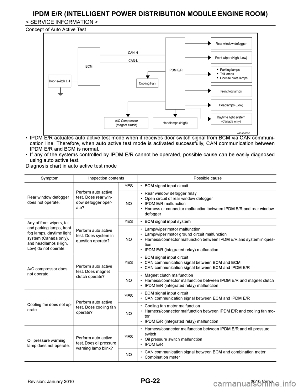
Concept of Auto Active Test
• IPDM E/R actuates auto active test mode when it re ceives door switch signal from BCM via CAN communi-
cation line. Therefore, when auto active test mode is activated successfully, CAN communication between
IPDM E/R and BCM is normal.
• If any of the systems controll ed by IPDM E/R cannot be operated, possible cause can be easily diagnosed
using auto active test.
Diagnosis chart in auto active test mode
WKIA5665E
Symptom Inspection contents Possible cause
Rear window defogger
does not operate. Perform auto active
test. Does rear win-
dow defogger oper-
ate?YES • BCM signal input circuit
NO • Rear window defogger relay
• Open circuit of rear window defogger
•IPDM E/R malfunction
• Harness or connector malfunction between IPDM E/R and rear window
defogger
Any of front wipers, tail
and parking lamps, front
fog lamps, daytime light
system (Canada only),
and headlamps (High,
Low) do not operate. Perform auto active
test. Does system in
question operate?YES • BCM signal input system
NO • Lamp/wiper motor malfunction
• Lamp/wiper motor ground circuit malfunction
• Harness/connector malfunction between IPDM E/R and system in ques-
tion
• IPDM E/R (integrated relay) malfunction
A/C compressor does
not operate. Perform auto active
test. Does magnet
clutch operate?YES
• BCM signal input circuit
• CAN communication signal between BCM and ECM
• CAN communication signal between ECM and IPDM E/R
NO • Magnet clutch malfunction
• Harness/connector malfunction between IPDM E/R and magnet clutch
• IPDM E/R (integrated relay) malfunction
Cooling fan does not op-
erate. Perform auto active
test. Does cooling fan
operate?YES
• ECM signal input circuit
• CAN communication signal between ECM and IPDM E/R
NO • Cooling fan motor malfunction
• Harness/connector malfunction between IPDM E/R and cooling fan mo-
tor
• IPDM E/R (integrated relay) malfunction
Oil pressure warning
lamp does not operate. Perform auto active
test. Does oil pressure
warning lamp blink?YES
• Harness/connector malfunction between IPDM E/R and oil pressure
switch
• Oil pressure switch malfunction
•IPDM E/R
NO • CAN communication signal between BCM and combination meter
• Combination meter
Revision: January 20102010 Versa
Page 3411 of 3745
PG-28
< SERVICE INFORMATION >
IPDM E/R (INTELLIGENT POWER DISTRIBUTION MODULE ENGINE ROOM)
OK or NG
OK >> GO TO 3.
NG >> Repair or replace IPDM E/R power circuit harness.
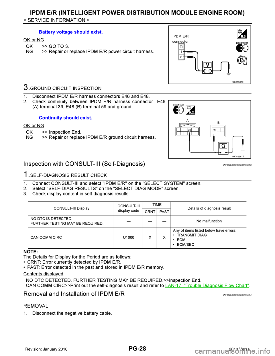
3.GROUND CIRCUIT INSPECTION
1. Disconnect IPDM E/R harness connectors E46 and E48.
2. Check continuity between IPDM E/R harness connector E46 (A) terminal 39, E48 (B) terminal 59 and ground.
OK or NG
OK >> Inspection End.
NG >> Repair or replace IPDM E/R ground circuit harness.
Inspection with CONSULT-III (Self-Diagnosis)INFOID:0000000005395363
1.SELF-DIAGNOSIS RESULT CHECK
1. Connect CONSULT-III and select "IPDM E/R" on the "SELECT SYSTEM" screen.
2. Select "SELF-DIAG RESULTS" on the "SELECT DIAG MODE" screen.
3. Check display content in self-diagnosis results.
NOTE:
The Details for Display for the Period are as follows:
• CRNT: Error currently detected by IPDM E/R.
• PAST: Error detected in the past and stored in IPDM E/R memory.
Contents displayed
NO DTC DETECTED. FURTHER TESTING MAY BE REQUIRED.>>Inspection End.
CAN COMM CIRC>>Print out the self-diagnosis result and refer to LAN-17, "
Trouble Diagnosis Flow Chart".
Removal and Installation of IPDM E/RINFOID:0000000005395364
REMOVAL
1. Disconnect the negative battery cable.Battery voltage should exist.
SKIA1987E
Continuity should exist.
WKIA5667E
CONSULT-III Display
CONSULT-III
display code TIME
Details of diagnosis result
CRNT PAST
NO DTC IS DETECTED.
FURTHER TESTING MAY BE REQUIRED. — — —
No malfunction
CAN COMM CIRC U1000 X XAny of items listed below have errors:
• TRANSMIT DIAG
•ECM
• BCM/SEC
Revision: January 20102010 Versa
Page 3424 of 3745

HARNESSPG-41
< SERVICE INFORMATION >
C
DE
F
G H
I
J
L
M A
B
PG
N
O P
C2 M6 W/4 : Steering lock solenoid D2 M43 W/20 : Audio unit
B3 M7 W/16 : Door mirror re mote control switch D2 M44 W/16 : Audio unit
A3 M8 W/16 : To D2 D2 M45 W/12 : Audio unit
A3 M9 W/16 : To D1 A1 M46 BR/2 : Front tweeter LH
E2 M10 GR/2 : Instrument panel antenna G1 M47 BR/2 : Front tweeter RH
G3 M11 W/4 : To B106 B2 M48 L/4 : Heated mirror relay
G4 M12 W/16 : To B101 E1 M49 W/24 : iPod ® adapter
G3 M13 W/24 : To B102 E1 M50 GR/16 : iPod ® side
G3 M14 W/24 : To B120 E2 M52 W/40 : Intelligent key unit
B4 M15 W/16 : To B23 B2 M53 W/16 : EPS control unit
B4 M16 W/24 : To B24 B3 M54 B/2 : EPS control unit
D5 M17 B/1 : Parking brake switch D2 M55 W/4 : Hazard switch
F2 M18 W/40 : BCM (body control module) B2 M57 — : Body ground
F2 M19 W/15 : BCM (body control module) F2 M59 W/2 : Glove box lamp
F3 M20 B/15 : BCM (body control module)C1 M60 L/2 : EPS control unit
C2 M21 W/4 : NATS antenna amp. F1 M61 — : Body ground
B3 M22 W/16 : Data link connector E2 M62 W/2 : Front blower motor
E3 M23 W/4 : Remote keyless entry receiver C1 M63 W/4 : Torque sensor
C1 M24 W/40 : Combination meter C3 M64 W/8 : Steering angle sensor
C3 M25 /2 : Diode-1 A2 M69 SMJ : To E7
B2 M26 W/6 : Ignition switch D2 M70 W/24 : AV control unit
C2 M27 GR/6 : Key switch and key lock solenoid D2 M71 W/9 : AV control unit
C2 M28 W/16 : Combination switch D1 M72 B/5 : USB interface and aux jack
C3 M29 Y/6 : Combination switch B2 M73 GR/6 : Key switch and ignition knob switch
C3 M30 GR/8 : Combination switch G3 M74 W/12 : To D102
A4 M31 W/24 : To B1 G3 M75 W/12 : To D101
E3 M32 W/4 : To M150 E1 M76 B/4 : USB interface and aux jack
D2 M33 B/15 : Front air control F2 M77 Y/4 : Front passenger air bag module
B3 M34 GR/6 : VDC OFF switch A2 M78 B/2 : To E11
D4 M35 Y/28 : Air bag diagnosis sensor unit B1 M79 — : Body ground
C3 M36 W/3 : Front passenger air bag OFF indicator D3 M150 W/4 : To M32
D4 M38 W/6 : A/T shift selector (with A/T) C3 M151 W/4 : Front blower motor resistor
D4 M38 W/6 : CVT shift selector (without intelligent
key)
Revision: January 20102010 Versa
Page 3467 of 3745

STEERING COLUMNPS-9
< SERVICE INFORMATION >
C
DE
F
H I
J
K L
M A
B
PS
N
O P
STEERING COLUMN
Removal and InstallationINFOID:0000000005396936
COMPONENT
CAUTION:
• Do not allow axial impact to steering colu mn assembly during removal and installation.
• Steering column must be kept at maximum tilt up position during removal and installation. Do not
operate tilt mechanism while steeri ng column is out of the vehicle.
• Put matching mark on intermediate shaft and st eering column assembly before removing intermedi-
ate shaft.
• When steering wheel is turned re peatedly with the vehicle stopped, care must be taken because
motor and EPS control unit may get too hot.
• Steering column assembly is heavy. Care must be taken when removing steering column assembly
from vehicle.
• Do not put steering column assem bly near the things that generate excessive magnetic force.
• Steering column assembly (with motor, reduc tion gear, sensor) cannot be disassembled.
• Any time the ignition switch h as been removed and installed, the keys must be re-registered in the
BCM. Refer to CONSULT–III ope ration manual IVIS/NVIS.
REMOVAL
1. Set front wheels to straight ahead-position.
2. Remove spiral cable. Refer to SRS-37
.
3. Remove instrument lower finisher. Refer to IP-11, "
Component Parts".
4. Disconnect each switch connector installed to steering column assembly, and then disconnect harness from steering column assembly.
5. Remove bolt of intermediate shaft (upper side), and then remove intermediate shaft from steering column assembly.
1. Steering wheel 2. Steering column assembly (with mo-
tor, reduction gear, sensor) 3. Bracket
4. EPS control unit 5. Intermediate shaft
AWGIA0017GB
Revision: January 20102010 Versa
Page 3485 of 3745

RF-1
BODY
C
DE
F
G H
J
K L
M
SECTION RF
A
B
RF
N
O P
CONTENTS
ROOF
PRECAUTION ....... ........................................2
PRECAUTIONS .............................................. .....2
Precaution for Supplemental Restraint System
(SRS) "AIR BAG" and "SEAT BELT PRE-TEN-
SIONER" ............................................................. ......
2
Precaution Necessary for Steering Wheel Rota-
tion After Battery Disconnect ............................... ......
2
Precaution .................................................................3
PREPARATION ............................................4
PREPARATION .............................................. .....4
Commercial Service Tool .................................... ......4
SYMPTOM DIAGNOSIS ...............................5
SQUEAK AND RATTLE TROUBLE DIAG-
NOSES ........................ ........................................
5
Work Flow ........................................................... ......5
Generic Squeak and Rattle Troubleshooting ............7
Diagnostic Worksheet ...............................................9
FUNCTION DIAGNOSIS ..............................11
TROUBLE DIAGNOSIS ................................. ....11
Component Parts and Harness Connector Loca-
tion ....................................................................... ....
11
System Description ..................................................11
CAN Communication System Description ...............13
Wiring Diagram - SROOF - ......................................14
Terminal and Reference Value for BCM ..................15
Terminal and Reference Value for Sunroof Motor
Assembly ............................................................. ....
16
Work Flow ................................................................16
CONSULT-III Function (BCM) .................................16
Work Support ....................................................... ....17
Active Test ...............................................................17
Data Monitor ............................................................17
Trouble Diagnosis Chart by Symptom .....................17
BCM Power Supply and Ground Circuit Inspection
....
17
Sunroof Switch System Inspection ..........................17
Sunroof Motor Assembly Power Supply and
Ground Circuit Inspection ........................................
19
Door Switch Check ..................................................20
ON-VEHICLE REPAIR .................................22
SUNROOF .........................................................22
Removal and Installation ..................................... ....22
Fitting Adjustment ....................................................27
Inspection ................................................................28
Revision: January 20102010 Versa