2010 NISSAN TIIDA fuel type
[x] Cancel search: fuel typePage 2551 of 3745
![NISSAN TIIDA 2010 Service Repair Manual EM-192
< SERVICE INFORMATION >[MR18DE]
ENGINE ASSEMBLY
• Use either 2-pole lift type or separate type lift as
best you can. If board-on type is used for unavoid-
able reasons, support at the rear a NISSAN TIIDA 2010 Service Repair Manual EM-192
< SERVICE INFORMATION >[MR18DE]
ENGINE ASSEMBLY
• Use either 2-pole lift type or separate type lift as
best you can. If board-on type is used for unavoid-
able reasons, support at the rear a](/manual-img/5/57397/w960_57397-2550.png)
EM-192
< SERVICE INFORMATION >[MR18DE]
ENGINE ASSEMBLY
• Use either 2-pole lift type or separate type lift as
best you can. If board-on type is used for unavoid-
able reasons, support at the rear axle jacking point with a transmission jack or similar tool before
starting work, in preparation for the backward shift of center of gravity.
• For supporting points for lifting and jacking point at rear axle, refer to GI-38, "
Garage Jack and
Safety Stand and 2-Pole Lift".
REMOVAL
Remove the engine and the transaxle assembly from t he vehicle downward. Separate the engine and the tran-
saxle.
1. Remove engine under cover. Refer to EI-15, "
Removal and Installation".
2. Drain engine coolant from radiator. Refer to CO-36, "
Changing Engine Coolant".
CAUTION:
• Perform this step when the engine is cold.
• Do not spill engine coolant on drive belt.
3. Drain clutch fluid (M/T models). Refer to CL-9, "
Air Bleeding Procedure".
4. Drain M/T oil (M/T models). Refer to MT-54, "
Changing M/T Oil".
5. Remove front fender protector (RH and LH). Refer to EI-24
.
6. Remove exhaust front tube. Refer to EX-11
.
7. Remove drive shafts (LH and RH) from steering knuckle. Refer to FA X - 9
.
8. Remove transaxle joint bolts which pierce at oil pan (upper) lower rear side. Refer to AT-233
(A/T models),
CVT-173, "
Removal and Installation" (CVT models) or MT-61, "Removal and Installation" (M/T models).
9. Remove rear torque rod (1). NOTE:
A/T model shown CVT and M/T models similar.
10. Remove hood assembly. Refer to BL-13
.
11. Remove cowl top cover and cowl top extension assembly. Refer to EI-22
.
12. Release fuel pressure. Refer to EC-582, "
Fuel Pressure Check".
13. Remove battery and battery tray. Refer to SC-5
.
14. Remove drive belt; Refer to EM-132, "
Component".
15. Remove engine room cover.
16. Remove air duct and air cleaner case assembly. Refer to EM-135
.
17. Remove cooling fan assembly. Refer to CO-43, "
Removal and Installation".
18. Remove radiator hose (upper and lower). Refer to CO-40
.
19. Disconnect A/T, CVT fluid cooler hoses (A/T or CVT models). Refer to CO-40
.
20. Disconnect all connections of engine harness around the engine mounting insulator (LH), and then tem- porarily secure the engine harness into the engine side.
CAUTION:
Protect connectors using a resin bag to protect against foreign materials during the operation.
21. Disconnect fuel feed hose at engine side. Refer to EM-152, "
Component".
22. Disconnect heater hoses, and install plugs in them to prevent engine coolant from draining. Refer to CO-
48, "Component".
23. Disconnect control cable from transaxle. Refer to CVT-173, "
Removal and Installation" (CVT models), AT-
213 (A/T models) or MT-61, "Removal and Installation" (M/T models).
24. Remove ground cable at transaxle side.
25. Remove ground cable between front cover and vehicle.
26. Remove generator. Refer to SC-21
.
LBIA0460E
Revision: January 20102010 Versa
Page 2654 of 3745

FRONT SUSPENSION ASSEMBLYFSU-7
< SERVICE INFORMATION >
C
DF
G H
I
J
K L
M A
B
FSU
N
O P
FRONT SUSPENSION ASSEMBLY
On-Vehicle Inspection and ServiceINFOID:0000000005397061
Make sure the mounting conditions (looseness, back lash) of each component and component conditions
(wear, damage) are normal.
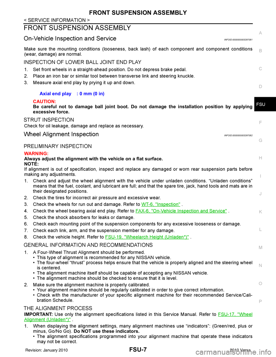
INSPECTION OF LOWER BALL JOINT END PLAY
1. Set front wheels in a straight-ahead position. Do not depress brake pedal.
2. Place an iron bar or similar tool between transverse link and steering knuckle.
3. Measure axial end play by prying it up and down.
CAUTION:
Be careful not to damage ball joint boot. Do not damage the installation position by applying
excessive force.
STRUT INSPECTION
Check for oil leakage, damage and replace as necessary.
Wheel Alignment InspectionINFOID:0000000005397062
PRELIMINARY INSPECTION
WARNING:
Always adjust the alignment with the vehicle on a flat surface.
NOTE:
If alignment is out of specification, inspect and replace any damaged or worn rear suspension parts before
making any adjustments.
1. Check and adjust the wheel alignment with the vehicle under unladen conditions. “Unladen conditions”
means that the fuel, coolant, and lubricant are full; and that the spare tire, jack, hand tools and mats are in
their designated positions.
2. Check the tires for incorrect air pressure and excessive wear.
3. Check the wheels for run out and damage. Refer to WT-6, "
Inspection" .
4. Check the wheel bearing axial end play. Refer to FAX-6, "
On-Vehicle Inspection and Service" .
5. Check the shock absorbers for leaks or damage.
6. Check each mounting point of the suspension components for any excessive looseness or damage.
7. Check each link, arm, and the suspension member for any damage.
8. Check the vehicle height. Refer to FSU-19, "
Wheelarch Height (Unladen*)" .
GENERAL INFORMATION AND RECOMMENDATIONS
1. A Four-Wheel Thrust Alignment should be performed.
• This type of alignment is re commended for any NISSAN vehicle.
• The four-wheel “thrust” process helps ensure that the vehicle is properly aligned and the steering wheel
is centered.
• The alignment machine itself should be ca pable of accepting any NISSAN vehicle.
• The alignment machine should be checked to ensure that it is level.
2. Make sure the alignment machine is properly calibrated. • Your alignment machine should be regularly calibrated in order to give correct information.
• Check with the manufacturer of your specific a lignment machine for their recommended Service/Cali-
bration Schedule.
THE ALIGNMENT PROCESS
IMPORTANT: Use only the alignment specifications listed in this Service Manual. Refer to FSU-17, "Wheel
Alignment (Unladen*)" .
1. When displaying the alignment settings, many alignm ent machines use “indicators”: (Green/red, plus or
minus, Go/No Go). Do NOT use these indicators.
• The alignment specifications programmed into your alignment machine that operate these indicators may not be correct.Axial end play : 0 mm (0 in)
Revision: January 20102010 Versa
Page 3044 of 3745

FRONT FOG LAMPLT-49
< SERVICE INFORMATION >
C
DE
F
G H
I
J
L
M A
B
LT
N
O P
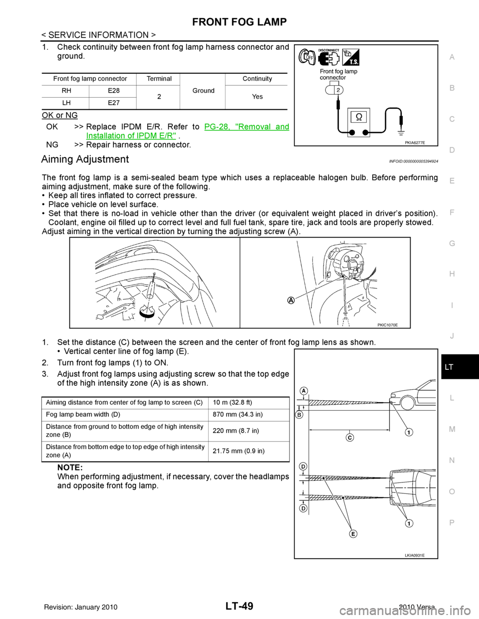
1. Check continuity between front fog lamp harness connector and ground.
OK or NG
OK >> Replace IPDM E/R. Refer to PG-28, "Removal and
Installation of IPDM E/R" .
NG >> Repair harness or connector.
Aiming AdjustmentINFOID:0000000005394924
The front fog lamp is a semi-sealed beam type whic h uses a replaceable halogen bulb. Before performing
aiming adjustment, make sure of the following.
• Keep all tires inflated to correct pressure.
• Place vehicle on level surface.
• Set that there is no-load in vehicle other than the driver (or equivalent weight placed in driver’s position). Coolant, engine oil filled up to correct level and full fuel tank, spare tire, jack and tools are properly stowed.
Adjust aiming in the vertical direction by turning the adjusting screw (A).
1. Set the distance (C) between the screen and the c enter of front fog lamp lens as shown.
• Vertical center line of fog lamp (E).
2. Turn front fog lamps (1) to ON.
3. Adjust front fog lamps using adjusting screw so that the top edge of the high intensity zone (A) is as shown.
NOTE:
When performing adjustment, if necessary, cover the headlamps
and opposite front fog lamp.
Front fog lamp connector Terminal
Ground Continuity
RH E28
2Y es
LH E27
PKIA6277E
PKIC1070E
Aiming distance from center of fog lamp to screen (C) 10 m (32.8 ft)
Fog lamp beam width (D) 870 mm (34.3 in)
Distance from ground to bottom edge of high intensity
zone (B) 220 mm (8.7 in)
Distance from bottom edge to top edge of high intensity
zone (A) 21.75 mm (0.9 in)
LKIA0931E
Revision: January 20102010 Versa
Page 3144 of 3745

PERIODIC MAINTENANCEMA-9
< SERVICE INFORMATION >
C
DE
F
G H
I
J
K
M A
B
MA
N
O P
PERIODIC MAINTENANCE
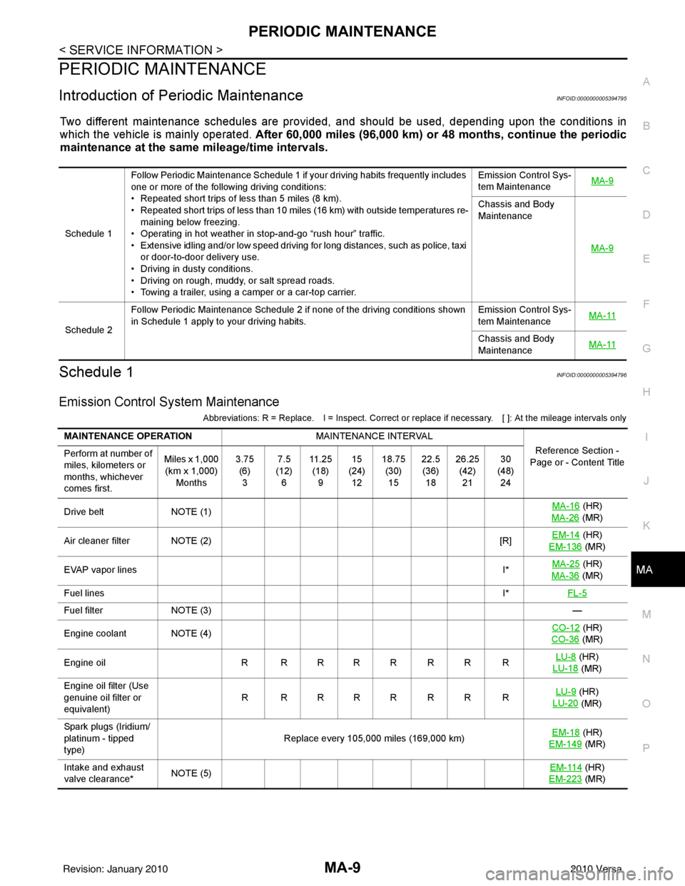
Introduction of Periodic MaintenanceINFOID:0000000005394795
Two different maintenance schedules are provi ded, and should be used, depending upon the conditions in
which the vehicle is mainly operated. After 60,000 miles (96,000 km) or 48 months, continue the periodic
maintenance at the same mileage/time intervals.
Schedule 1INFOID:0000000005394796
Emission Control System Maintenance
Abbreviations: R = Replace. I = Inspect. Correct or r eplace if necessary. [ ]: At the mileage intervals only
Schedule 1Follow Periodic Maintenance Schedule 1 if your driving habits frequently includes
one or more of the following driving conditions:
• Repeated short trips of less than 5 miles (8 km).
• Repeated short trips of less than 10 miles (16 km) with outside temperatures re-
maining below freezing.
• Operating in hot weather in stop-and-go “rush hour” traffic.
• Extensive idling and/or low speed driving for long distances, such as police, taxi
or door-to-door delivery use.
• Driving in dusty conditions.
• Driving on rough, muddy, or salt spread roads.
• Towing a trailer, using a camper or a car-top carrier. Emission Control Sys-
tem Maintenance
MA-9
Chassis and Body
Maintenance
MA-9
Schedule 2Follow Periodic Maintenance Schedule 2 if none of the driving conditions shown
in Schedule 1 apply to your driving habits.
Emission Control Sys-
tem Maintenance
MA-11Chassis and Body
Maintenance
MA-11
MAINTENANCE OPERATION
MAINTENANCE INTERVAL
Reference Section -
Page or - Content Title
Perform at number of
miles, kilometers or
months, whichever
comes first. Miles x 1,000
(km x 1,000) Months 3.75
(6)3 7.5
(12) 6 11 . 2 5
(18) 9 15
(24) 12 18.75
(30)15 22.5
(36) 18 26.25
(42)21 30
(48) 24
Drive belt NOTE (1) MA-16
(HR)
MA-26
(MR)
Air cleaner filter NOTE (2) [R]EM-14
(HR)
EM-136
(MR)
EVAP vapor lines I*MA-25
(HR)
MA-36
(MR)
Fuel lines I*FL-5
Fuel filter NOTE (3) —
Engine coolant NOTE (4) CO-12
(HR)
CO-36
(MR)
Engine oil R R R R R R R R LU-8
(HR)
LU-18
(MR)
Engine oil filter (Use
genuine oil filter or
equivalent) RRRRRRRR
LU-9
(HR)
LU-20
(MR)
Spark plugs (Iridium/
platinum - tipped
type) Replace every 105,000 miles (169,000 km)
EM-18
(HR)
EM-149
(MR)
Intake and exhaust
valve clearance* NOTE (5) EM-114
(HR)
EM-223
(MR)
Revision: January 20102010 Versa
Page 3145 of 3745
![NISSAN TIIDA 2010 Service Repair Manual MA-10
< SERVICE INFORMATION >
PERIODIC MAINTENANCE
Abbreviations: R = Replace. I = Inspect. Correct or replace if necessary. [ ]: At the mileage intervals only
(1) After 60,000 miles (96,000 km) or 48 NISSAN TIIDA 2010 Service Repair Manual MA-10
< SERVICE INFORMATION >
PERIODIC MAINTENANCE
Abbreviations: R = Replace. I = Inspect. Correct or replace if necessary. [ ]: At the mileage intervals only
(1) After 60,000 miles (96,000 km) or 48](/manual-img/5/57397/w960_57397-3144.png)
MA-10
< SERVICE INFORMATION >
PERIODIC MAINTENANCE
Abbreviations: R = Replace. I = Inspect. Correct or replace if necessary. [ ]: At the mileage intervals only
(1) After 60,000 miles (96,000 km) or 48 months, inspect every 15,000 miles (24,000 km) or 12 months. Replace the drive belts i f found
damaged.
(2) If operating mainly in dusty conditions, more frequent maintenance may be required.
(3) Maintenance-free item. For service procedures, go to the FL section.
(4) After 60,000 miles (96,000 km) or 48 months, replace every 30,000 miles (48,000 km) or 24 months.
(5) Periodic maintenance is not required. However, if valve noise increases, inspect valve clearance.
* Maintenance items and intervals with “*” are recommended by NISSAN for reliable vehicle operation. The owner need not perform
such maintenance in order to maintain the emission warranty or manufacturer recall liability. Other maintenance items and inter vals are
required.
Chassis and Body Maintenance
Abbreviations: R = Replace. I = Inspect. Corr ect or replace if necessary. L = Lubricate.
MAINTENANCE OPERATIONMAINTENANCE INTERVAL
Reference Section -
Page or - Content Title
Perform at number of
miles, kilometers or
months, whichever
comes first. Miles x
1,000
(km x
1,000)
Months 33.75
(54)27 37.5
(60) 30 41.25
(66)33 45
(72) 36 48.75
(78)39 52.5
(84) 42 56.25
(90)45 60
(96) 48
Drive belt NOTE
(1) I*EM-14
(HR)
EM-132
(MR)
Air cleaner filter NOTE
(2) [R]
EM-17
(HR)
EM-135
(MR)
EVAP vapor lines I*MA-25
(HR)
MA-36
(MR)
Fuel lines I*FL-5
Fuel filter NOTE
(3) —
Engine coolant NOTE
(4) R*
CO-12
(HR)
CO-36
(MR)
Engine oil R R R R R R R R LU-8
(HR)
LU-18
(MR)
Engine oil filter (Use
genuine oil filter or
equivalent) R R R R RRRR
LU-9
(HR)
LU-20
(MR)
Spark plugs (Iridium/
platinum - tipped type) Replace every 105,000 miles (169,000 km) EM-18
(HR)
EM-149
(MR)
Intake and exhaust
valve clearance* NOTE
(5) EM-114
(HR)
EM-223
(MR)
MAINTENANCE OPERATION MAINTENANCE INTERVAL
Reference Section -
Page or -
Content Title
Perform at number of
miles, kilometers or
months, whichever
comes first. Miles x
1,000
(km x
1,000)
Months 3.75
(6)3 7.5
(12) 6 11 . 2 5
(18) 9 15
(24) 12 18.75
(30)15 22.5
(36) 18 26.25
(42)21 30
(48) 24
Brake lines & cables IIMA-45
Brake pads, rotors,
drums & linings IIII MA-45
MA-46
Manual transaxle oil or
automatic transaxle
fluid IIMT-11
(RS5F91R) MT-54
(RS6F94R)
AT- 1 7
(A/T)
CVT fluid NOTE (1) IICVT-14
(RE0F08B)
Revision: January 20102010 Versa
Page 3147 of 3745
![NISSAN TIIDA 2010 Service Repair Manual MA-12
< SERVICE INFORMATION >
PERIODIC MAINTENANCE
Abbreviations: R = Replace. I = Inspect. Correct or replace if necessary. [ ]: At the mileage intervals only
(1) After 60,000 miles (96,000 km) or 48 NISSAN TIIDA 2010 Service Repair Manual MA-12
< SERVICE INFORMATION >
PERIODIC MAINTENANCE
Abbreviations: R = Replace. I = Inspect. Correct or replace if necessary. [ ]: At the mileage intervals only
(1) After 60,000 miles (96,000 km) or 48](/manual-img/5/57397/w960_57397-3146.png)
MA-12
< SERVICE INFORMATION >
PERIODIC MAINTENANCE
Abbreviations: R = Replace. I = Inspect. Correct or replace if necessary. [ ]: At the mileage intervals only
(1) After 60,000 miles (96,000 km) or 48 months, inspect every 15,000 miles (24,000 km) or 12 months. Replace the drive belt if found
damaged or if the auto belt tensioner reading reaches the maximum limit.
(2) Maintenance-free item.
(3) After 60,000 miles (96,000 km) or 48 months, replace every 30,000 miles (48,000 km) or 24 months.
(4) Periodic maintenance is not required. However, if valve noise increases, inspect valve clearance.
Maintenance items and intervals with “*” are recommended by NISSAN for reliab le vehicle operation. The owner need not perform such
maintenance in order to maintain the emission warranty or manufacturer recall liability. Other maintenance items and intervals are
required.
Chassis and Body Maintenance
Abbreviations: R = Replace. I = Inspect. Correct or replace if necessary. L = Lubricate.
MAINTENANCE OPERATION MAINTENANCE INTERVAL
Reference
Section - Page
or - Content Ti- tle
Perform at number of miles,
kilometers or months, which-
ever comes first. Miles x
1,000
(km x
1,000)
Months 7.5
(12) 6 15
(24) 12 22.5
(36) 18 30
(48) 24 37.5
(60) 30 45
(72) 36 52.5
(84) 42 60
(96) 48
Drive belt NOTE (1) I*EM-14
(HR)
EM-132
(MR)
Air cleaner filter [R][R]EM-17
(HR)
EM-136
(MR)
EVAP vapor lines I*I*MA-25
(HR)
MA-36
(MR)
Fuel lines I*I*FL-5
Fuel filter NOTE (2) —
Engine coolant NOTE (3) R*CO-12
(HR)
CO-36
(MR)
Engine oil RR R RRRRR LU-8
(HR)
LU-18
(MR)
Engine oil filter (Use genuine
oil filter or equivalent.) RR R RRRRR LU-9
(HR)
LU-20
(MR)
Spark plugs (Iridium/plati-
num - tipped type) Replace every 105,000 miles (169,000 km) EM-18
(HR)
EM-149
(MR)
Intake and exhaust valve
clearance* NOTE (4)
EM-114
(HR)
EM-223
(MR)
MAINTENANCE OPERATION MAINTENANCE INTERVAL
Reference Sec-
tion - Page or -
Content Title
Perform at number of miles, kilo-
meters or months, whichever
comes first. Miles x 1,000
(km x 1,000)
Months 7.5
(12)
6 15
(24)
12 22.5
(36)
18 30
(48)
24 37.5
(60)
30 45
(72)
36 52.5
(84)
42 60
(96)
48
B ra ke lin e s & cab le s IIII MA-45
Brake pads, rotors, drums & lin-
ings IIII
MA-45
MA-46
Manual transaxle oil or automatic
transaxle fluid IIIIMT-11
(RS5F91R)
MT-54
(RS6F94R)
AT- 1 7
(A/T)
C VT flu id NO TE (1) IIII CVT-15
(RE0F08B)
Steering gear & linkage, axle &
suspension parts II
PS-12
, MA-47
Tire rotation NOTE (2) WT-7
Fro n t d riv e s ha ft b oo ts IIII MA-47
Revision: January 20102010 Versa
Page 3149 of 3745

MA-14
< SERVICE INFORMATION >
RECOMMENDED FLUIDS AND LUBRICANTS
RECOMMENDED FLUIDS AND LUBRICANTS
Fluids and LubricantsINFOID:0000000005394798
*1: For further details, see “Engine Oil Recommendation”.
*2: If genuine NISSAN gear oil is not available, API GL-4, Viscosity SAE 75W-80 may be used as a temporary replacement. However
use Genuine NISSAN gear oil as soon as it is possible.
*3: Using transaxle fluid other than Genuine NISSAN CVT Fluid NS-2 will damage the CVT, which is not covered by the NISSAN
new vehicle limited warranty.
*4: Available in mainland U.S.A. through a NISSAN dealer.
*5: For further details, see “Air conditioner specification label”.
*6: If Genuine NISSAN Matic S ATF is not available, Genuine NISSIAN Matic D ATF may also be used. Using automatic transmission
other than Genuine NISSAN Matic S or Genuine NISSIAN Matic D ATF will cause deteri oration in driveability and automatic transmis-
sion durability, and may damage the automatic transmission, which is not covered by NISSAN new vehicle limited warranty.
SAE Viscosity NumberINFOID:0000000005394799
NISSAN recommends the use of an energy conservi ng oil in order to improve fuel economy.
DescriptionCapacity (Approximate)
Recommended Fluids/Lubricants
Liter US measure Imp measure
Fuel 50.0 13 1/4 gal 11 galUnleaded gasoline with an octane rat-
ing of at least 87 AKI (RON 91)
Engine oil
Drain and refill With oil filter
change
HR16DE 3.0 3 1/8 qt 2 5/8 qt
• Engine oil with API Certification Mark *1
• Viscosity SAE 5W-30
MR18DE 4.1 4 3/8 qt 3 5/8 qt
Without oil
filter change HR16DE 2.8
3 qt 2 1/2 qt
MR18DE 3.9 4 1/8 qt 3 3/8 qt
Dry engine (engine overhaul) HR16DE 3.5 3 3/4 qt 3 1/8 qt
MR18DE 4.9 5 1/8 qt 4 3/8 qt
Cooling system
(with reservoir at max level) HR16DE 6.3 6 5/8 qt 5 1/2 qt Genuine
NISSAN Long Life Anti-freeze
Coolant or equivalent
MR18DE 6.8 7 1/4 qt 6 qt
Manual transaxle fluid (MTF) 5MT
2.6 5 1/2 pt 4 5/8 pt Genuine NISSAN Manual Transmis-
sion Fluid (MTF) HQ Multi 75W-85 or
API GL-4, Viscosity SAE 75W-85
6MT 2.0 4 1/4 pt 3 1/2 pt Genuine NISSAN gear oil (XT4447
M+) 75W-80, Genuine NISSAN gear oil
(ETL8997B) 75W-80, or equivalent *2
Automatic transaxle fluid (ATF) HR16DE 7.7 8 1/8 qt 6 3/4 qt
Genuine NISSAN Matic S ATF recom-
mended *6
MR18DE 7.9 8 3/8 qt 7 qt
CVT fluid RE0F08B 7.4 7 7/8 qt 6 1/2 qt Genuine NISSAN CVT Fluid NS-2 *3
Brake and clutch fluid ———Genuine NISSAN Su
per Heavy Duty
Brake Fluid*4 or equivalent DOT 3 (US
FMVSS No. 116)
Multi-purpose grease ——— NLGI No. 2 (Lithium soap base)
Windshield washer fluid 4.5 4 3/4 qt 4 qtGenuine NISSAN Windshield Washer
Concentrate Cleaner & Anti-Freeze or
equivalent
Air conditioning system refrigerant 0.45 ± 0.05 kg 0.99 ± 0.11 lb 0.99 ± 0.11 lb HFC-134a (R-134a) *5
Air conditioning system oil MR18DE
Type 1 and
HR16DE
120 m
4.1 fl oz 4.2 fl oz NISSAN A/C System Lubricant Type R
or equivalent *5
MR18DE
Typ e 2 100 m
3.4 fl oz 3.5 fl oz NISSAN A/C System Lubricant Type S
or equivalent *5
Revision: January 20102010 Versa
Page 3339 of 3745

MTC-60
< SERVICE INFORMATION >
A/C UNIT ASSEMBLY
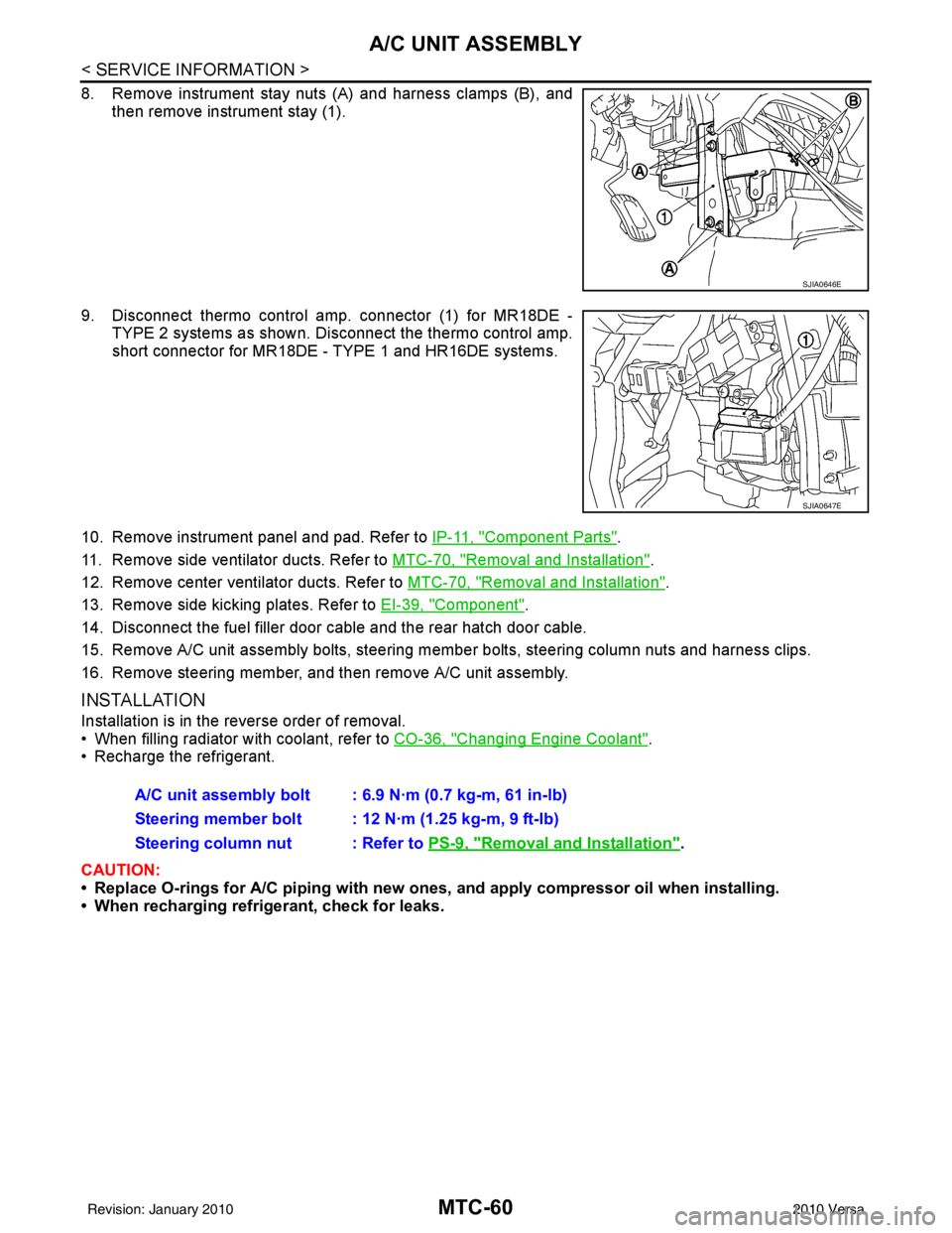
8. Remove instrument stay nuts (A) and harness clamps (B), andthen remove instrument stay (1).
9. Disconnect thermo control amp. connector (1) for MR18DE - TYPE 2 systems as shown. Di sconnect the thermo control amp.
short connector for MR18DE - TYPE 1 and HR16DE systems.
10. Remove instrument panel and pad. Refer to IP-11, "
Component Parts".
11. Remove side ventilator ducts. Refer to MTC-70, "
Removal and Installation".
12. Remove center ventilator ducts. Refer to MTC-70, "
Removal and Installation".
13. Remove side kicking plates. Refer to EI-39, "
Component".
14. Disconnect the fuel filler door cable and the rear hatch door cable.
15. Remove A/C unit assembly bolts, steering member bolts, steering column nuts and harness clips.
16. Remove steering member, and then remove A/C unit assembly.
INSTALLATION
Installation is in the reverse order of removal.
• When filling radiator with coolant, refer to CO-36, "
Changing Engine Coolant".
• Recharge the refrigerant.
CAUTION:
• Replace O-rings for A/C piping with new ones, and apply compressor oil when installing.
• When recharging refrigerant, check for leaks.
SJIA0646E
SJIA0647E
A/C unit assembly bolt : 6.9 N·m (0.7 kg-m, 61 in-lb)
Steering member bolt : 12 N·m (1.25 kg-m, 9 ft-lb)
Steering column nut : Refer to PS-9, "
Removal and Installation".
Revision: January 20102010 Versa