2010 NISSAN TIIDA coolant
[x] Cancel search: coolantPage 2575 of 3745
![NISSAN TIIDA 2010 Service Repair Manual EM-216
< SERVICE INFORMATION >[MR18DE]
CYLINDER BLOCK
Measure the outer diameter of piston pin with a micrometer (A).
Connecting Rod Bushing Oil Clearance
(Connecting rod bushing oil clearance) = (Con NISSAN TIIDA 2010 Service Repair Manual EM-216
< SERVICE INFORMATION >[MR18DE]
CYLINDER BLOCK
Measure the outer diameter of piston pin with a micrometer (A).
Connecting Rod Bushing Oil Clearance
(Connecting rod bushing oil clearance) = (Con](/manual-img/5/57397/w960_57397-2574.png)
EM-216
< SERVICE INFORMATION >[MR18DE]
CYLINDER BLOCK
Measure the outer diameter of piston pin with a micrometer (A).
Connecting Rod Bushing Oil Clearance
(Connecting rod bushing oil clearance) = (Connecting rod bus
hing inner diameter) – (Piston pin outer diame-
ter)
• If the measured value is out of the standard, repl ace connecting rod assembly and/or piston and piston pin
assembly.
• If replacing piston and piston pin assembly, follow the "PISTON TO PISTON PIN OIL CLEARANCE" proce-
dure.
• If replacing connecting rod assembly, follow the "Connecting Rod Bushing Oil Clearance" procedure to select connecting rod bearing.
CYLINDER BLOCK TOP SURFACE DISTORTION
• Using a scraper, remove gasket on the cylinder block su rface, and also remove engine oil, scale, carbon, or
other contamination.
CAUTION:
Be careful not to allow gasket flakes to en ter engine oil or engine coolant passages.
• Measure the distortion on the cylinder block upper face at some
different points in six directions with a straight edge (A) and feeler
gauge (B).
• If it exceeds the limit, replace cylinder block.
MAIN BEARING HOUSING INNER DIAMETER
• Install main bearing cap without main bearings install ed, and tighten main bearing cap bolts to the specified
torque. Refer to EM-196, "
Disassembly and Assembly" for the tightening procedure.
• Measure the inner diameter of main bearing housing with a bore gauge.
• Measure the position shown [5 mm (0.20 in)] backward from main bearing housing front side in the 2 directions as shown. The
smaller one is the measured value.
• If out of the standard, replace cylinder block and main bearing caps assembly.
NOTE: Standard: 19.989 - 19.995 mm (0.7870 - 0.7872 in)
PBIC3266J
Standard : 0.005 - 0.023 mm (0.0002 - 0.0009 in)
Limit : 0.03 mm (0.0012 in)
Limit: 0.1 mm (0.004 in)
PBIC3250J
1 : Cylinder block
2 : Main bearing cap
: Engine front
Standard: 55.997 - 56.017 mm (2.2046 - 2.2054 in)
PBIC4005E
Revision: January 20102010 Versa
Page 2650 of 3745
PRECAUTIONSFSU-3
< SERVICE INFORMATION >
C
DF
G H
I
J
K L
M A
B
FSU
N
O P
5. When the repair work is completed, return the ignition switch to the ″LOCK ″ position before connecting
the battery cables. (At this time, the steering lock mechanism will engage.)
6. Perform a self-diagnosis check of al l control units using CONSULT-III.
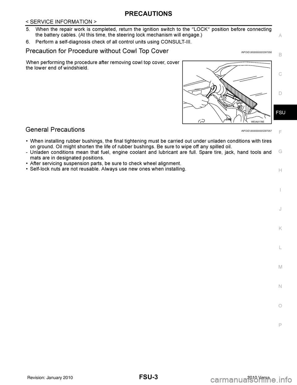
Precaution for Procedure without Cowl Top CoverINFOID:0000000005397056
When performing the procedure after removing cowl top cover, cover
the lower end of windshield.
General PrecautionsINFOID:0000000005397057
• When installing rubber bushings, the final tightening mu st be carried out under unladen conditions with tires
on ground. Oil might shorten the life of rubber bushings. Be sure to wipe off any spilled oil.
- Unladen conditions mean that fuel, engine coolant and l ubricant are full. Spare tire, jack, hand tools and
mats are in designated positions.
• After servicing suspension parts, be sure to check wheel alignment.
• Self-lock nuts are not reusable. A lways use new ones when installing.
WEIA0178E
Revision: January 20102010 Versa
Page 2654 of 3745
FRONT SUSPENSION ASSEMBLYFSU-7
< SERVICE INFORMATION >
C
DF
G H
I
J
K L
M A
B
FSU
N
O P
FRONT SUSPENSION ASSEMBLY
On-Vehicle Inspection and ServiceINFOID:0000000005397061
Make sure the mounting conditions (looseness, back lash) of each component and component conditions
(wear, damage) are normal.
INSPECTION OF LOWER BALL JOINT END PLAY
1. Set front wheels in a straight-ahead position. Do not depress brake pedal.
2. Place an iron bar or similar tool between transverse link and steering knuckle.
3. Measure axial end play by prying it up and down.
CAUTION:
Be careful not to damage ball joint boot. Do not damage the installation position by applying
excessive force.
STRUT INSPECTION
Check for oil leakage, damage and replace as necessary.
Wheel Alignment InspectionINFOID:0000000005397062
PRELIMINARY INSPECTION
WARNING:
Always adjust the alignment with the vehicle on a flat surface.
NOTE:
If alignment is out of specification, inspect and replace any damaged or worn rear suspension parts before
making any adjustments.
1. Check and adjust the wheel alignment with the vehicle under unladen conditions. “Unladen conditions”
means that the fuel, coolant, and lubricant are full; and that the spare tire, jack, hand tools and mats are in
their designated positions.
2. Check the tires for incorrect air pressure and excessive wear.
3. Check the wheels for run out and damage. Refer to WT-6, "
Inspection" .
4. Check the wheel bearing axial end play. Refer to FAX-6, "
On-Vehicle Inspection and Service" .
5. Check the shock absorbers for leaks or damage.
6. Check each mounting point of the suspension components for any excessive looseness or damage.
7. Check each link, arm, and the suspension member for any damage.
8. Check the vehicle height. Refer to FSU-19, "
Wheelarch Height (Unladen*)" .
GENERAL INFORMATION AND RECOMMENDATIONS
1. A Four-Wheel Thrust Alignment should be performed.
• This type of alignment is re commended for any NISSAN vehicle.
• The four-wheel “thrust” process helps ensure that the vehicle is properly aligned and the steering wheel
is centered.
• The alignment machine itself should be ca pable of accepting any NISSAN vehicle.
• The alignment machine should be checked to ensure that it is level.
2. Make sure the alignment machine is properly calibrated. • Your alignment machine should be regularly calibrated in order to give correct information.
• Check with the manufacturer of your specific a lignment machine for their recommended Service/Cali-
bration Schedule.
THE ALIGNMENT PROCESS
IMPORTANT: Use only the alignment specifications listed in this Service Manual. Refer to FSU-17, "Wheel
Alignment (Unladen*)" .
1. When displaying the alignment settings, many alignm ent machines use “indicators”: (Green/red, plus or
minus, Go/No Go). Do NOT use these indicators.
• The alignment specifications programmed into your alignment machine that operate these indicators may not be correct.Axial end play : 0 mm (0 in)
Revision: January 20102010 Versa
Page 2664 of 3745
SERVICE DATA AND SPECIFICATIONS (SDS)FSU-17
< SERVICE INFORMATION >
C
DF
G H
I
J
K L
M A
B
FSU
N
O P
SERVICE DATA AND SPECIFICATIONS (SDS)
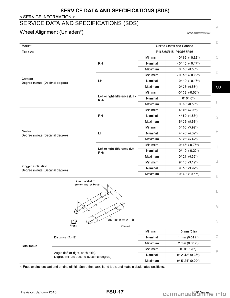
Wheel Alignment (Unladen*)INFOID:0000000005397069
*: Fuel, engine coolant and engine oil full. Spare tire, jack, hand tools and mats in designated positions. Market
United States and Canada
Tire size P185/65R15, P195/55R16
Camber
Degree minute (Decimal degree) RH
Minimum - 0
° 55 ′ (- 0.92 °)
Nominal - 0 ° 10 ′ (- 0.17 °)
Maximum 0 ° 35 ′ (0.58 °)
LH Minimum
- 0° 55 ′ (- 0.92 °)
Nominal - 0° 10 ′ (- 0.17 °)
Maximum 0° 35 ′ (0.58 °)
Left or right difference (LH -
RH) Minimum
-0° 33 ′ (-0.55 °)
Nominal 0° 0 ′ (0 °)
Maximum 0° 33 ′ (0.55 °)
Caster
Degree minute (Decimal degree) RH
Minimum
4° 05 ′ (4.08 °)
Nominal 4° 50 ′ (4.83 °)
Maximum 5° 35 ′ (5.58 °)
LH Minimum
3° 55 ′ (3.92 °)
Nominal 4
° 40 ′ (4.67 °)
Ma
ximum 5° 25 ′ (5.42 °)
Left or right difference (LH -
RH) Minimum
-0° 45 ′ (-0.75 °)
Nominal -0° 12 ′ (-0.20 °)
Maximum 0° 21 ′ (0.35 °)
Kingpin inclination
Degree minute (Decimal degree) Minimum
9° 10 ′ (9.17 °)
Nominal 9° 55 ′ (9.92 °)
Maximum 10° 40 ′ (10.67 °)
Total toe-in Distance (A - B)
Minimum
0 mm (0 in)
Nominal 1 mm (0.04 in)
Maximum 2 mm (0.08 in)
Angle (left or right, each side)
Degree minute second (Decimal degree) Minimum
0° 0 ′ 0" (0 °)
Nominal 0° 2 ′ 42" (0.05 °)
Maximum 0° 5 ′ 24" (0.09 °)
SFA234AC
Revision: January 20102010 Versa
Page 2665 of 3745
FSU-18
< SERVICE INFORMATION >
SERVICE DATA AND SPECIFICATIONS (SDS)
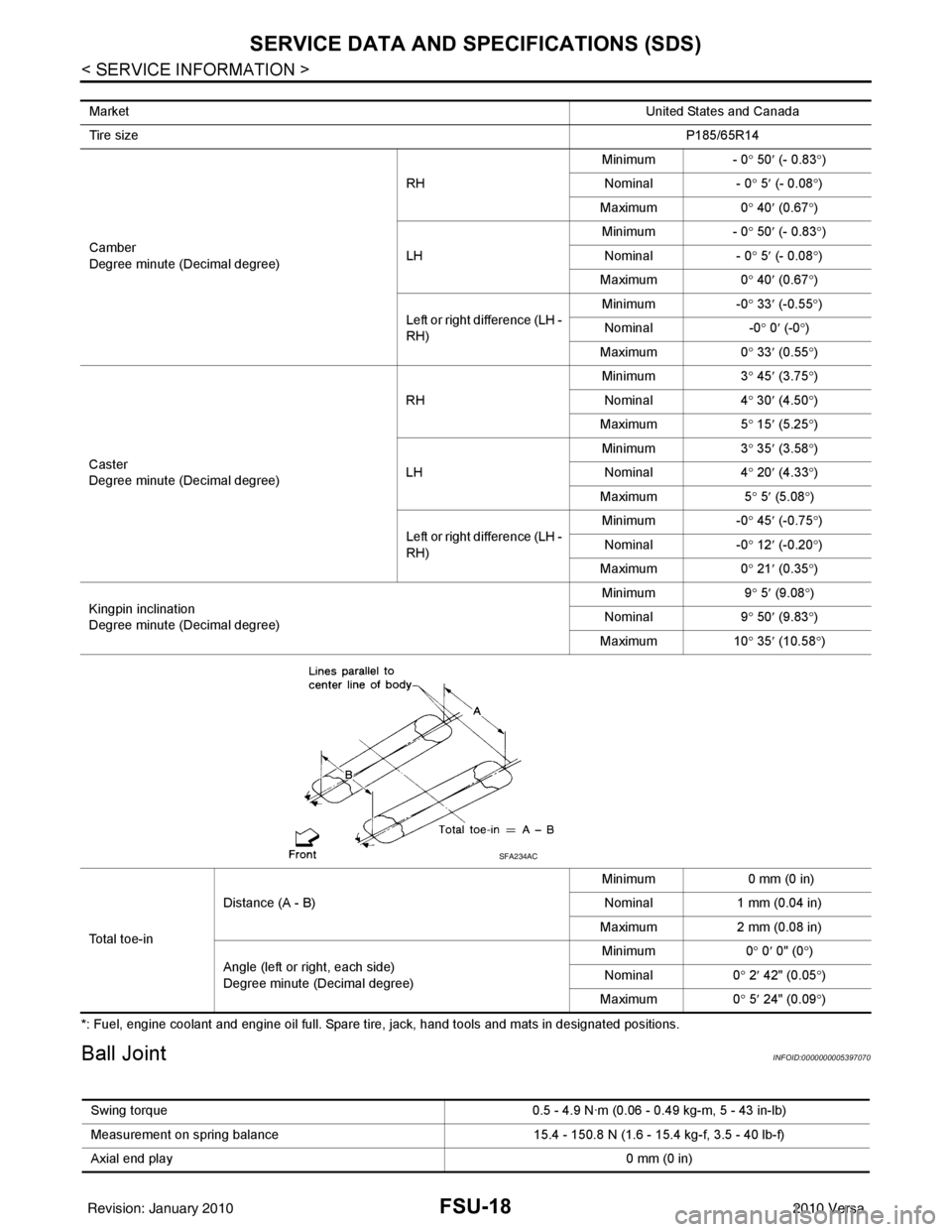
*: Fuel, engine coolant and engine oil full. Spare tire, jack, hand tools and mats in designated positions.
Ball JointINFOID:0000000005397070
MarketUnited States and Canada
Tire size P185/65R14
Camber
Degree minute (Decimal degree) RH
Minimum
- 0° 50 ′ (- 0.83 °)
Nominal - 0° 5 ′ (- 0.08 °)
Maximum 0° 40 ′ (0.67 °)
LH Minimum
- 0° 50 ′ (- 0.83 °)
Nominal - 0° 5 ′ (- 0.08 °)
Maximum 0° 40 ′ (0.67 °)
Left or right difference (LH -
RH) Minimum
-0° 33 ′ (-0.55 °)
Nominal -0° 0 ′ (-0 °)
Maximum 0° 33 ′ (0.55 °)
Caster
Degree minute (Decimal degree) RH
Minimum
3° 45 ′ (3.75 °)
Nominal 4° 30 ′ (4.50 °)
Maximum 5° 15 ′ (5.25 °)
LH Minimum
3° 35 ′ (3 .58
°)
Nominal 4° 20 ′ (4
.33°)
Maximum 5° 5 ′ (5.08 °)
Left or right difference (LH -
RH) Minimum
-0° 45 ′ (-0.75 °)
Nominal -0° 12 ′ (-0.20 °)
Maximum 0° 21 ′ (0.35 °)
Kingpin inclination
Degree minute (Decimal degree) Minimum
9° 5 ′ (9.08 °)
Nominal 9° 50 ′ (9.83 °)
Maximum 10° 35 ′ (10.58 °)
To t a l t o e - i n Distance (A - B)
Minimum
0 mm (0 in)
Nominal 1 mm (0.04 in)
Maximum 2 mm (0.08 in)
Angle (left or right, each side)
Degree minute (Decimal degree) Minimum
0° 0 ′ 0" (0 °)
Nominal 0° 2 ′ 42" (0.05 °)
Maximum 0° 5 ′ 24" (0.09 °)
SFA234AC
Swing torque 0.5 - 4.9 N·m (0.06 - 0.49 kg-m, 5 - 43 in-lb)
Measurement on spring balance 15.4 - 150.8 N (1.6 - 15.4 kg-f, 3.5 - 40 lb-f)
Axial end play 0 mm (0 in)
Revision: January 20102010 Versa
Page 2666 of 3745
SERVICE DATA AND SPECIFICATIONS (SDS)FSU-19
< SERVICE INFORMATION >
C
DF
G H
I
J
K L
M A
B
FSU
N
O P
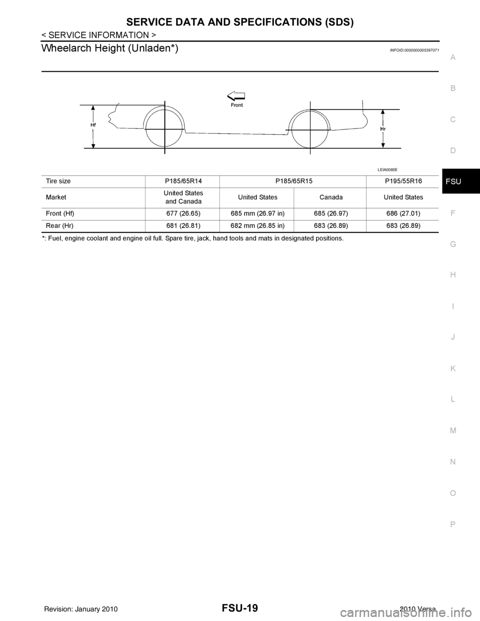
Wheelarch Height (Unladen*)INFOID:0000000005397071
*: Fuel, engine coolant and engine oil full. Spare tire, jack, hand tools and mats in designated positions. Tire size
P185/65R14P185/65R15P195/55R16
Market United States
and Canada United States
CanadaUnited States
Front (Hf) 677 (26.65) 685 mm (26.97 in) 685 (26.97) 686 (27.01)
Rear (Hr) 681 (26.81) 682 mm (26.85 in) 683 (26.89) 683 (26.89)
LEIA0085E
Revision: January 20102010 Versa
Page 2714 of 3745

GI-48
< SERVICE INFORMATION >
TERMINOLOGY
TERMINOLOGY
SAE J1930 Terminology ListINFOID:0000000005399867
All emission related terms used in this publication in accordance with SAE J1930 are listed. Accordingly, new
terms, new acronyms/abbreviations and old terms are listed in the following chart.
NEW TERMNEW ACRONYM /
ABBREVIATION OLD TERM
Air cleaner ACL Air cleaner
Barometric pressure BARO ***
Barometric pressure sensor-BCDD BAROS-BCDD BCDD
Camshaft position CMP ***
Camshaft position sensor CMPSCrank angle sensor
Canister *** Canister
Carburetor CARBCarburetor
Charge air cooler CACIntercooler
Closed loop CLClosed loop
Closed throttle position switch CTP switchIdle switch
Clutch pedal position switch CPP switch Clutch switch
Continuous fuel injection system CFI system***
Continuous trap oxidizer system CTOX system ***
Crankshaft position CKP***
Crankshaft position sensor CKPS***
Data link connector DLC***
Data link connector for CONSULT-III DLC for CONSULT-IIIDiagnostic connector for CONSULT-III
Diagnostic test mode DTMDiagnostic mode
Diagnostic test mode selector DTM selectorDiagnostic mode selector
Diagnostic test mode I DTM I Mode I
Diagnostic test mode II DTM IIMode II
Diagnostic trouble code DTCMalfunction code
Direct fuel injection system DFI system ***
Distributor ignition system DI system Ignition timing control
Early fuel evaporation-mixture heater EFE-mixture heater Mixture heater
Early fuel evaporation system EFE system Mixture heater control
Electrically erasable programmable read
only memory EEPROM
***
Electronic ignition system EI systemIgnition timing control
Engine control EC ***
Engine control module ECM ECCS control unit
Engine coolant temperature ECT Engine temperature
Engine coolant temperature sensor ECTS Engine temperature sensor
Engine modification EM ***
Engine speed RPM Engine speed
Erasable programmable read only memory EPROM ***
Evaporative emission canister EVAP canister Canister
Evaporative emission system EVAP system Canister control solenoid valve
Exhaust gas recirculation valve EGR valve EGR valve
Revision: January 20102010 Versa
Page 2836 of 3745
![NISSAN TIIDA 2010 Service Repair Manual CAN COMMUNICATION SYSTEMLAN-27
< SERVICE INFORMATION > [CAN]
C
D
E
F
G H
I
J
L
M A
B
LAN
N
O P
CAN Communication Signal ChartINFOID:0000000005395135
Refer to LAN-16, "How to Use CAN Communication Sig NISSAN TIIDA 2010 Service Repair Manual CAN COMMUNICATION SYSTEMLAN-27
< SERVICE INFORMATION > [CAN]
C
D
E
F
G H
I
J
L
M A
B
LAN
N
O P
CAN Communication Signal ChartINFOID:0000000005395135
Refer to LAN-16, "How to Use CAN Communication Sig](/manual-img/5/57397/w960_57397-2835.png)
CAN COMMUNICATION SYSTEMLAN-27
< SERVICE INFORMATION > [CAN]
C
D
E
F
G H
I
J
L
M A
B
LAN
N
O P
CAN Communication Signal ChartINFOID:0000000005395135
Refer to LAN-16, "How to Use CAN Communication Signal Chart" for how to use CAN communication signal
chart.
NOTE:
Refer to LAN-22, "
Abbreviation List" for the abbreviations of the connecting units.
T: Transmit R: Receive
Signal name/Connecting unitECM
BCM
EPS
I-KEY M&A
STRG ABS
TCM
*1
TCM
*2
IPDM-E
A/C compressor request signal T R
Accelerator pedal position signal T
R
*3RR
ASCD CRUISE lamp signal T R
ASCD SET lamp signal T R
Closed throttle position signal T R R
Cooling fan motor operation signal T R
Engine coolant temperature signal TR
Engine speed signal TR
R
*3R
Engine status signal T R R R
Fuel consumption monitor signal T R
Malfunction indicator lamp signal TR
Wide open throttle position signal T R R
A/C switch signal R T
Blower fan motor switch signal R T
Buzzer output signal TR
TR
Day time running light request signal
*4TR
Door lock/unlock status signal TR
Door switch signal TR R R
Front wiper request signal T R
High beam request signal TR R
Horn chirp signal T R
Ignition switch signal T R
Low beam request signal T R
Position lights request signal TR R
Rear window defogger switch signal T R
Sleep/wake up signal TRR
R
RT
Theft warning horn request signal T R
Tire pressure signal
*5TR
Trunk open/close status signal TR
Turn indicator signal TR
EPS operation signal TR
EPS warning lamp signal TR
Door lock/unlock/trunk open request signal RT
Hazard request signal RT
Ignition knob switch signal RT
Revision: January 20102010 Versa