2010 NISSAN TIIDA ignition
[x] Cancel search: ignitionPage 561 of 3745
BL-52
< SERVICE INFORMATION >
POWER DOOR LOCK SYSTEM
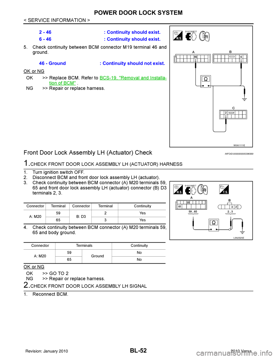
5. Check continuity between BCM connector M19 terminal 46 andground.
OK or NG
OK >> Replace BCM. Refer to BCS-19, "Removal and Installa-
tion of BCM" .
NG >> Repair or replace harness.
Front Door Lock Assembly LH (Actuator) CheckINFOID:0000000005396569
1.CHECK FRONT DOOR LOCK ASSEMBLY LH (ACTUATOR) HARNESS
1. Turn ignition switch OFF.
2. Disconnect BCM and front door lock assembly LH (actuator).
3. Check continuity between BCM connector (A) M20 terminals 59, 65 and front door lock assembly LH (actuator) connector (B) D3
terminals 2, 3.
4. Check continuity between BCM connector (A) M20 terminals 59, 65 and body ground.
OK or NG
OK >> GO TO 2
NG >> Repair or replace harness.
2.CHECK FRONT DOOR LOCK ASSEMBLY LH SIGNAL
1. Reconnect BCM. 2 - 46
: Continuity should exist.
6 - 46 : Continuity should exist.
46 - Ground : Continuity should not exist.
WIIA1111E
Connector Terminal Connector Terminal Continuity
A: M20 59
B: D3 2Y
es
65 3Yes
Connector Terminals Continuity
A: M20 59
Ground No
65 No
LIIA2525E
Revision: January 20102010 Versa
Page 562 of 3745
POWER DOOR LOCK SYSTEMBL-53
< SERVICE INFORMATION >
C
DE
F
G H
J
K L
M A
B
BL
N
O P
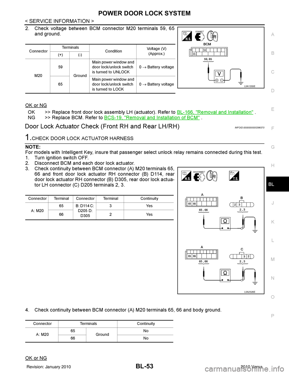
2. Check voltage between BCM connector M20 terminals 59, 65 and ground.
OK or NG
OK >> Replace front door lock assembly LH (actuator). Refer to BL-166, "Removal and Installation" .
NG >> Replace BCM. Refer to BCS-19, "
Removal and Installation of BCM" .
Door Lock Actuator Check (Front RH and Rear LH/RH)INFOID:0000000005396570
1.CHECK DOOR LOCK ACTUATOR HARNESS
NOTE:
For models with Intelligent Key, insure that passenger select unlock relay remains connected during this test.
1. Turn ignition switch OFF.
2. Disconnect BCM and each door lock actuator.
3. Check continuity between BCM connector (A) M20 terminals 65, 66 and front door lock actuator RH connector (B) D114, rear
door lock actuator RH connector (B ) D305, rear door lock actua-
tor LH connector (C) D205 terminals 2, 3.
4. Check continuity between BCM connecto r (A) M20 terminals 65, 66 and body ground.
OK or NG
Connector Te r m i n a l s
ConditionVoltage (V)
(Approx.)
(+) (-)
M20 59
Ground Main power window and
door lock/unlock switch
is turned to UNLOCK
0
→ Battery voltage
65 Main power window and
door lock/unlock switch
is turned to LOCK 0
→ Battery voltage
LIIA1355E
Connector Terminal Connector Terminal Continuity
A: M20 65 B: D114 C:
D205 D:
D305 3Y
es
66 2Yes
LIIA2526E
Connector Terminals Continuity
A: M20 65
Ground No
66 No
Revision: January 20102010 Versa
Page 564 of 3745
POWER DOOR LOCK SYSTEMBL-55
< SERVICE INFORMATION >
C
DE
F
G H
J
K L
M A
B
BL
N
O P
1. Turn ignition switch OFF.
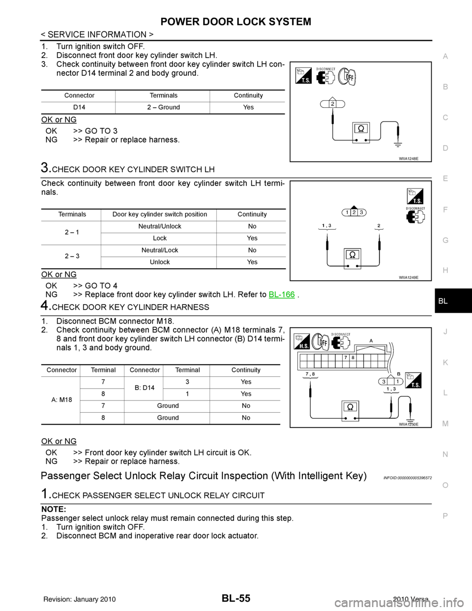
2. Disconnect front door key cylinder switch LH.
3. Check continuity between front door key cylinder switch LH con- nector D14 terminal 2 and body ground.
OK or NG
OK >> GO TO 3
NG >> Repair or replace harness.
3.CHECK DOOR KEY CYLINDER SWITCH LH
Check continuity between front door key cylinder switch LH termi-
nals.
OK or NG
OK >> GO TO 4
NG >> Replace front door key cylinder switch LH. Refer to BL-166
.
4.CHECK DOOR KEY CYLINDER HARNESS
1. Disconnect BCM connector M18.
2. Check continuity between BCM connector (A) M18 terminals 7, 8 and front door key cylinder switch LH connector (B) D14 termi-
nals 1, 3 and body ground.
OK or NG
OK >> Front door key cylinder switch LH circuit is OK.
NG >> Repair or replace harness.
Passenger Select Unlock Relay Circuit Inspection (With Intelligent Key)INFOID:0000000005396572
1.CHECK PASSENGER SELECT UNLOCK RELAY CIRCUIT
NOTE:
Passenger select unlock relay must remain connected during this step.
1. Turn ignition switch OFF.
2. Disconnect BCM and inoperative rear door lock actuator.
Connector TerminalsContinuity
D14 2 – Ground Yes
WIIA1248E
Terminals Door key cylinder switch position Continuity
2 – 1 Neutral/Unlock
No
Lock Yes
2 – 3 Neutral/Lock
No
Unlock Yes
WIIA1249E
Connector Terminal Connector Terminal Continuity
A: M18 7
B: D14 3Y
es
81Y es
7G ro un d N o
8G ro un d N o
WIIA1250E
Revision: January 20102010 Versa
Page 567 of 3745
BL-58
< SERVICE INFORMATION >
REMOTE KEYLESS ENTRY SYSTEM
REMOTE KEYLESS ENTRY SYSTEM
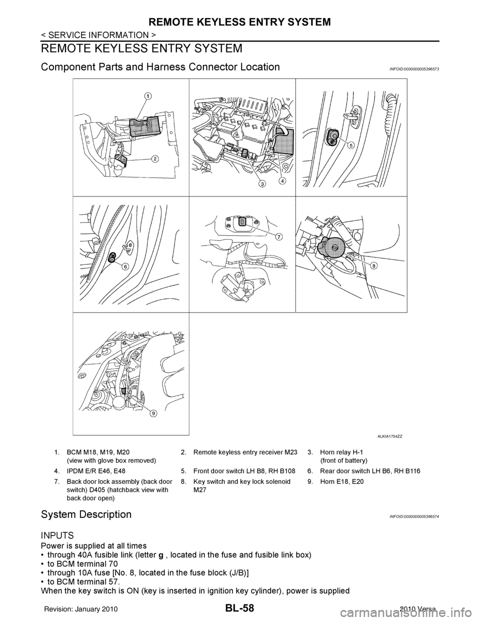
Component Parts and Harness Connector LocationINFOID:0000000005396573
System DescriptionINFOID:0000000005396574
INPUTS
Power is supplied at all times
• through 40A fusible link (letter g , located in the fuse and fusible link box)
• to BCM terminal 70
• through 10A fuse [No. 8, located in the fuse block (J/B)]
• to BCM terminal 57.
When the key switch is ON (key is inserted in ignition key cylinder), power is supplied
ALKIA1754ZZ
1. BCM M18, M19, M20
(view with glove box removed) 2. Remote keyless entry receiver M23 3. Horn relay H-1
(front of battery)
4. IPDM E/R E46, E48 5. Front door switch LH B8, RH B108 6. Rear door switch LH B6, RH B116
7. Back door lock assembly (back door switch) D405 (hatchback view with
back door open) 8. Key switch and key lock solenoid
M27 9. Horn E18, E20
Revision: January 20102010 Versa
Page 568 of 3745
![NISSAN TIIDA 2010 Service Repair Manual REMOTE KEYLESS ENTRY SYSTEMBL-59
< SERVICE INFORMATION >
C
DE
F
G H
J
K L
M A
B
BL
N
O P
• through 10A fuse [No. 14, located in the fuse block (J/B)]
• through key switch terminals 2 and 1
• to NISSAN TIIDA 2010 Service Repair Manual REMOTE KEYLESS ENTRY SYSTEMBL-59
< SERVICE INFORMATION >
C
DE
F
G H
J
K L
M A
B
BL
N
O P
• through 10A fuse [No. 14, located in the fuse block (J/B)]
• through key switch terminals 2 and 1
• to](/manual-img/5/57397/w960_57397-567.png)
REMOTE KEYLESS ENTRY SYSTEMBL-59
< SERVICE INFORMATION >
C
DE
F
G H
J
K L
M A
B
BL
N
O P
• through 10A fuse [No. 14, located in the fuse block (J/B)]
• through key switch terminals 2 and 1
• to BCM terminal 37.
When the ignition switch is ACC or ON, power is supplied
• through 10A fuse [No. 20, located in the fuse block (J/B)]
• to BCM terminal 11.
Ground is supplied
• to BCM terminal 67
• through body grounds M57 and M61.
When the front door switch LH is ON (door is OPEN), ground is supplied
• to BCM terminal 47
• through front door switch LH terminal 2
• through front door switch LH case ground.
When the front door switch RH is ON (door is OPEN), ground is supplied
• to BCM terminal 12
• through front door switch RH terminal 2
• through front door switch RH case ground.
When the rear door switch LH is ON (door is OPEN), ground is supplied
• to BCM terminal 48
• through rear door switch LH terminal 1
• through rear door switch LH case ground.
When the rear door switch RH is ON (door is OPEN), ground is supplied
• to BCM meter terminal 13
• through rear door switch RH terminal 1
• through rear door switch RH case ground.
When the back door lock assembly (back door switch) (hat chback) is ON (back door is OPEN), ground is sup-
plied
• to BCM terminal 43
• through back door lock assembly (back door switch) terminals 3 and 4
• through body grounds B117, B132 and D402.
Keyfob signal is inputted to BCM from remote keyless entry receiver.
The remote keyless entry system controls operation of the
• power door lock
• hazard reminder
• auto door lock
• panic alarm
• room lamp
OPERATED PROCEDURE
Power Door Lock Operation
BCM receives a LOCK signal from keyfob. BCM locks all doors with input of LOCK signal from keyfob.
BCM receives a UNLOCK signal from keyfob. BCM unlocks all doors with input of UNLOCK signal from key-
fob.
Hazard and Horn Reminder
When the doors are locked or unlocked by keyfob, power is supplied to sound horn and flash hazard warning
lamps as follows
• LOCK operation: 3 or 4 mode (lamps flash twice)
• UNLOCK operation: 2 or 4 mode (lamps flash once)
• Horn sounds once with LOCK function when this feature is set ON.
The hazard reminder has modes 1, 2, 3 or 4. The hor n reminder can be turned ON/OFF with any LOCK mode.
Operating function of hazard reminder
Hazard and horn reminders do not operate if any door switch is ON (any door is OPEN).
How to change hazard and horn reminder modes
Mode 1Mode 2Mode 3 Mode 4
Keyfob operation Lock Unlock Lock Unlock Lock Unlock Lock Unlock
Hazard warning lamp
flash — — — Twice Once — Once Twice
Horn sound (ON/OFF) ON: once — O N: once — ON: once — ON: once —
Revision: January 20102010 Versa
Page 569 of 3745
BL-60
< SERVICE INFORMATION >
REMOTE KEYLESS ENTRY SYSTEM
With CONSULT-III
Hazard reminder can be changed using “HAZARD LAMP SET” mode in “WORK SUPPORT”.
Horn reminder can be changed using “HORN CHIRP SET” mode in “WORK SUPPORT”.
Refer to BL-69, "
CONSULT-III Function (BCM)" .
Without CONSULT-III
Refer to Owner's Manual for instructions.
Auto Door Lock Operation
Auto lock function signal is sent for operation when any of the following signals are not sent within 1 minute
after the unlock signal is sent from the keyfob:
• when door switch is turned ON for open.
• when the key switch is turned ON.
• when the lock signal is sent from the keyfob.
Auto door lock mode can be changed using “AUT O LOCK SET” mode in “WORK SUPPORT”.
Refer to BL-69, "
CONSULT-III Function (BCM)" .
Panic Alarm Operation
When key switch is OFF (when ignition key is not inserted in key cylinder), BCM turns on and off horn intermit-
tently with input of PANIC ALARM signal from keyfob.
BCM outputs to IPDM E/R for panic alarm signal (horn signal) as DATA LINE (CAN H line and CAN L line).
The alarm automatically turns off after 25 seconds or when BCM receives any signal from keyfob.
Panic alarm operation mode can be changed using “P ANIC ALARM SET” mode in “WORK SUPPORT”.
Refer to BL-69, "
CONSULT-III Function (BCM)" .
Interior Lamp Operation
When the following conditions come:
• condition of interior lamp switch is in the DOOR position;
• door switch OFF (when all the doors are closed);
Remote keyless entry system turns on interior lamp (for 30 seconds) with input of UNLOCK signal from key-
fob. For detailed description, refer to LT- 9 4
.
CAN Communication System DescriptionINFOID:0000000005396575
Refer to LAN-7 .
Revision: January 20102010 Versa
Page 574 of 3745
REMOTE KEYLESS ENTRY SYSTEMBL-65
< SERVICE INFORMATION >
C
DE
F
G H
J
K L
M A
B
BL
N
O P
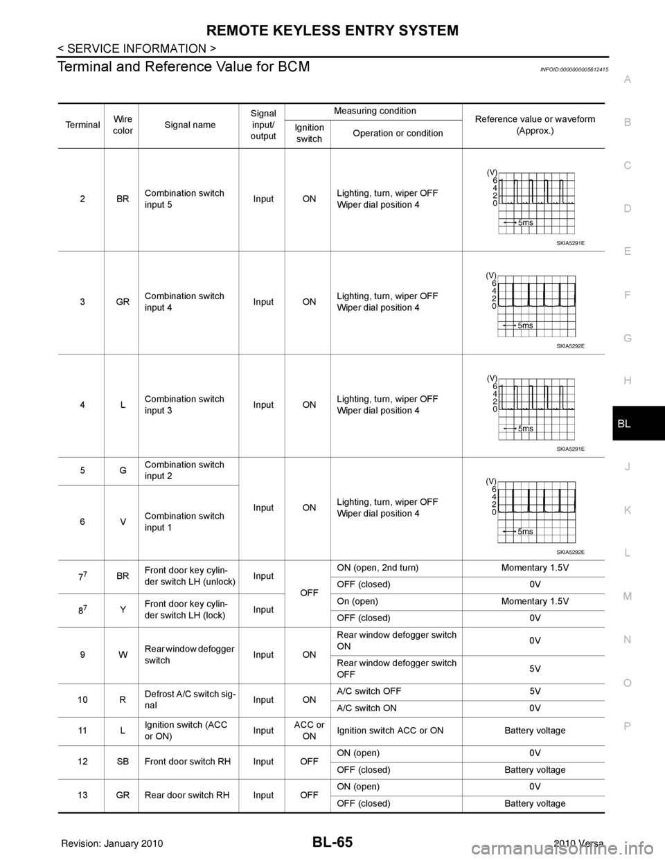
Terminal and Reference Value for BCMINFOID:0000000005612415
Te r m i n a l Wire
color Signal name Signal
input/
output Measuring condition
Reference value or waveform
(Approx.)
Ignition
switch Operation or condition
2BR Combination switch
input 5
Input ONLighting, turn, wiper OFF
Wiper dial position 4
3GR Combination switch
input 4 Input ONLighting, turn, wiper OFF
Wiper dial position 4
4L Combination switch
input 3
Input ONLighting, turn, wiper OFF
Wiper dial position 4
5G Combination switch
input 2
Input ONLighting, turn, wiper OFF
Wiper dial position 4
6V Combination switch
input 1
7
7BR Front door key cylin-
der switch LH (unlock) Input
OFFON (open, 2nd turn)
Momentary 1.5V
OFF (closed) 0V
8
7Y Front door key cylin-
der switch LH (lock) InputOn (open)
Momentary 1.5V
OFF (closed) 0V
9W Rear window defogger
switch Input ONRear window defogger switch
ON
0V
Rear window defogger switch
OFF 5V
10 R Defrost A/C switch sig-
nal
Input ONA/C switch OFF
5V
A/C switch ON 0V
11 L Ignition switch (ACC
or ON) InputACC or
ON Ignition switch ACC or ON
Battery voltage
12 SB Front door switch RH Input OFF ON (open)
0V
OFF (closed) Battery voltage
13 GR Rear door switch RH Input OFF ON (open)
0V
OFF (closed) Battery voltage
SKIA5291E
SKIA5292E
SKIA5291E
SKIA5292E
Revision: January 20102010 Versa
Page 575 of 3745
BL-66
< SERVICE INFORMATION >
REMOTE KEYLESS ENTRY SYSTEM
15 WTire pressure warning
check connector
Input OFF
—5V
18 V Remote keyless entry
receiver (ground) Output OFF
—0V
19 BR Remote keyless entry
receiver (power sup-
ply) Output OFF Ignition switch OFF
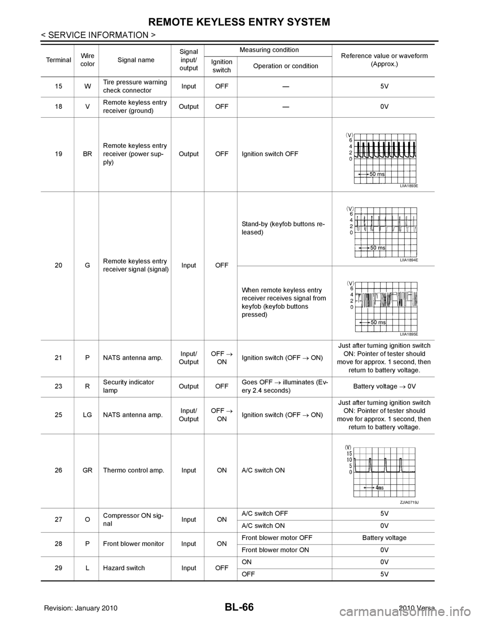
20 G Remote keyless entry
receiver signal (signal)
Input OFFStand-by (keyfob buttons re-
leased)
When remote keyless entry
receiver receives signal from
keyfob (keyfob buttons
pressed)
21 P NATS antenna amp. Input/
Output OFF
→
ON Ignition switch (OFF
→ ON)Just after turning ignition switch
ON: Pointer of tester should
move for approx. 1 second, then
return to battery voltage.
23 R Security indicator
lamp Output OFF
Goes OFF
→ illuminates (Ev-
ery 2.4 seconds) Battery voltage
→ 0V
25 LG NATS antenna amp. Input/
Output OFF
→
ON Ignition switch (OFF
→ ON)Just after turning ignition switch
ON: Pointer of tester should
move for approx. 1 second, then return to battery voltage.
26 GR Thermo control amp. Input ON A/C switch ON
27 O Compressor ON sig-
nal Input ONA/C switch OFF
5V
A/C switch ON 0V
28 P Front blower monitor Input ON Front blower motor OFF
Battery voltage
Front blower motor ON 0V
29 L Hazard switch Input OFFON
0V
OFF 5V
Te r m i n a l
Wire
color Signal name Signal
input/
output Measuring condition
Reference value or waveform
(Approx.)
Ignition
switch Operation or condition
LIIA1893E
LIIA1894E
LIIA1895E
ZJIA0719J
Revision: January 20102010 Versa