Page 523 of 3745
BL-14
< SERVICE INFORMATION >
HOOD
5. After adjustment tighten lock bolts to the specified torque.
6. Install the front grille. Refer to EI-21
.
Removal and InstallationINFOID:0000000005396548
HOOD ASSEMBLY
Removal
1. Remove hinge nuts on hood and remove hood assembly.
CAUTION:
Two technicians should be used to avoid damaging the
hood during removal.
1. Hood striker 2. Primary latch 3. Secondary striker
4. Secondary latch
A : 20 mm (0.79 in)
B : 6.8 mm (0.268 in) min.
PIIB5794E
1. Hood hinge 2. Hood stay3. Radiator core seal rubber
4. Hood assembly 5. Hood insulator 6. Hood stay holder
PIIB2528J
12.7 N·m (1.3 kg-m, 9.4 ft-lb)
PIIB2529J
Revision: January 20102010 Versa
Page 525 of 3745

BL-16
< SERVICE INFORMATION >
HOOD
Hood Lock Reinforcement
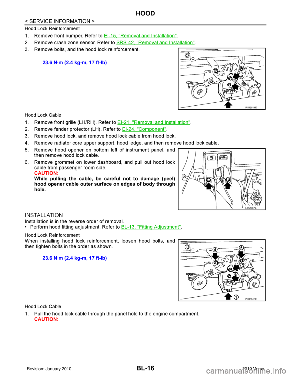
1. Remove front bumper. Refer to EI-15, "Removal and Installation".
2. Remove crash zone sensor. Refer to SRS-42, "
Removal and Installation".
3. Remove bolts, and the hood lock reinforcement.
Hood Lock Cable
1. Remove front grille (LH/RH). Refer to EI-21, "Removal and Installation".
2. Remove fender protector (LH). Refer to EI-24, "
Component".
3. Remove hood lock, and remove hood lock cable from hood lock.
4. Remove radiator core upper support, hood ledge, and then remove hood lock cable.
5. Remove hood opener on bottom left of instrument panel, and then remove hood lock cable.
6. Remove grommet on lower dashboard, and pull out hood lock cable from passenger room side.
CAUTION:
While pulling the cable, be car eful not to damage (peel)
hood opener cable outer surface on edges of body through
hole.
INSTALLATION
Installation is in the reverse order of removal.
• Perform hood fitting adjustment. Refer to BL-13, "
Fitting Adjustment".
Hood Lock Reinforcement
When installing hood lock reinforcement, loosen hood bolts, and
then tighten bolts in the order as shown.
Hood Lock Cable
1. Pull the hood lock cable through the panel hole to the engine compartment. CAUTION: 23.6 N·m (2.4 kg-m, 17 ft-lb)
PIIB6511E
LIIA2667E
23.6 N·m (2.4 kg-m, 17 ft-lb)
PIIB6513E
Revision: January 20102010 Versa
Page 528 of 3745

RADIATOR CORE SUPPORTBL-19
< SERVICE INFORMATION >
C
DE
F
G H
J
K L
M A
B
BL
N
O P
RADIATOR CORE SUPPORT
Removal and InstallationINFOID:0000000005396551
REMOVAL
Radiator Core Support Upper
1. Remove the air duct. Refer to EM-135, "Removal and Installation" .
2. Remove the headlamp (LH/RH). Refer to LT-26, "
Removal and Installation" .
3. Remove the hood lock assembly, and remove hood lock cable. Refer to BL-15
.
4. Remove the air guide and hood lock cable clip.
5. Remove the washer tank inlet. Refer to WW-24, "
Removal and Installation of Washer Tank" .
6. Remove the radiator core support upper.
Radiator Core Support Lower
1. Remove the air duct. Refer to EM-135, "Removal and Installation" .
2. Remove the front bumper. Refer to EI-15, "
Removal and Installation" .
3. Remove the headlamp (LH/RH). Refer to LT-26, "
Removal and Installation" .
4. Remove the hood lock assembly, and remove hood lock cable. Refer to BL-15
.
5. Remove the air guide and hood lock cable mounting clip.
6. Remove the front bumper reinforcement. Refer to EI-15, "
Removal and Installation" .
7. Remove the radiator core lower stay.
8. Remove the undercover.
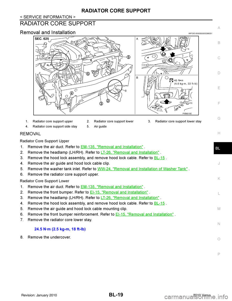
PIIB6515E
1. Radiator core support upper 2. Radiator core support lower 3. Radiator core support lower stay
4. Radiator core support side stay 5. Air guide
24.5 N·m (2.5 kg-m, 18 ft-lb)
Revision: January 20102010 Versa
Page 529 of 3745
BL-20
< SERVICE INFORMATION >
RADIATOR CORE SUPPORT
9. Remove radiator core support lower side stay.
10. Tie a cord to all radiator core upper supports of the radiator andcondenser.
NOTE:
To prevent the condensor and radiator from being dropped when
the radiator core lower support is removed.
11. Remove the bolts, and lower radiator core lower supports.
12. Remove the radiator core lower supports.
INSTALLATION
Installation is in the reverse order of removal. 55.0 N·m (5.6 kg-m, 41 ft-lb)
PIIB2800J
PIIB2799J
Revision: January 20102010 Versa
Page 779 of 3745

BL-270
< SERVICE INFORMATION >
BODY REPAIR
4. Front pillar inner reinforcement (RH&LH)
5. Lower dash reinforcement
6. 4th crossmember (RH&LH)
7. Front side member rear extension (RH&LH)
8. 3rd crossmember (RH&LH)
9. Front seat outer rear bracket (RH&LH)
10. Front seat inner rear bracket (RH&LH)
11. 2nd crossmember (RH&LH)
12. Front seat outer front bracket (RH&LH)
13. Front seat inner front bracket (RH&LH)
14. Fender bracket (RH&LH)
15. Strut housing assembly RH
16. Cowl top side upper (RH&LH)
17. Front strut housing (RH&LH)
18. Upper torque rod reinforcement
19. Closing plate assembly RH
20. Engine mount reinforcement
21. Strut tower front reinforcement RH
22. Front hoodledge lower RH
23. Frame bracket outer (RH&LH)
24. Front bumper support bracket (RH&LH)
25. Closing plate (RH&LH)
26. Front suspension rear bracket (RH&LH)
27. Front side member outrigger (RH&LH)
28. Front side member assembly (RH&LH)
29. Front side member (RH&LH)
30. Frame bracket (RH&LH)
31. Closing plate assembly LH
32. Hoodledge connector (RH&LH)
33. Radiator core side support (RH&LH)
34. Radiator core support upper (RH&LH)
35. Hoodledge upper (RH&LH)
36. Hoodledge reinforcement assembly (RH&LH)
37. Dash side (RH&LH)
38. Dash side assembly (RH& LH)
39. Front floor reinforcement (RH&LH)
40. Front floor front (RH&LH)
41. Front floor center
42. Rear seat crossmember
43. Rear center crossmember
44. Rear seat upper crossmember
45. Rear side member (RH&LH)
46. Sill inner extension (RH&LH)
47. Rear side member extension (RH&LH)
48. Rear side member assembly (RH & LH)
49. Rear floor front
50. Rear floor front assembly
51. Rear floor side (RH&LH)
52. Rear floor rear
Revision: January 20102010 Versa
Page 825 of 3745

BL-316
< SERVICE INFORMATION >
BODY REPAIR
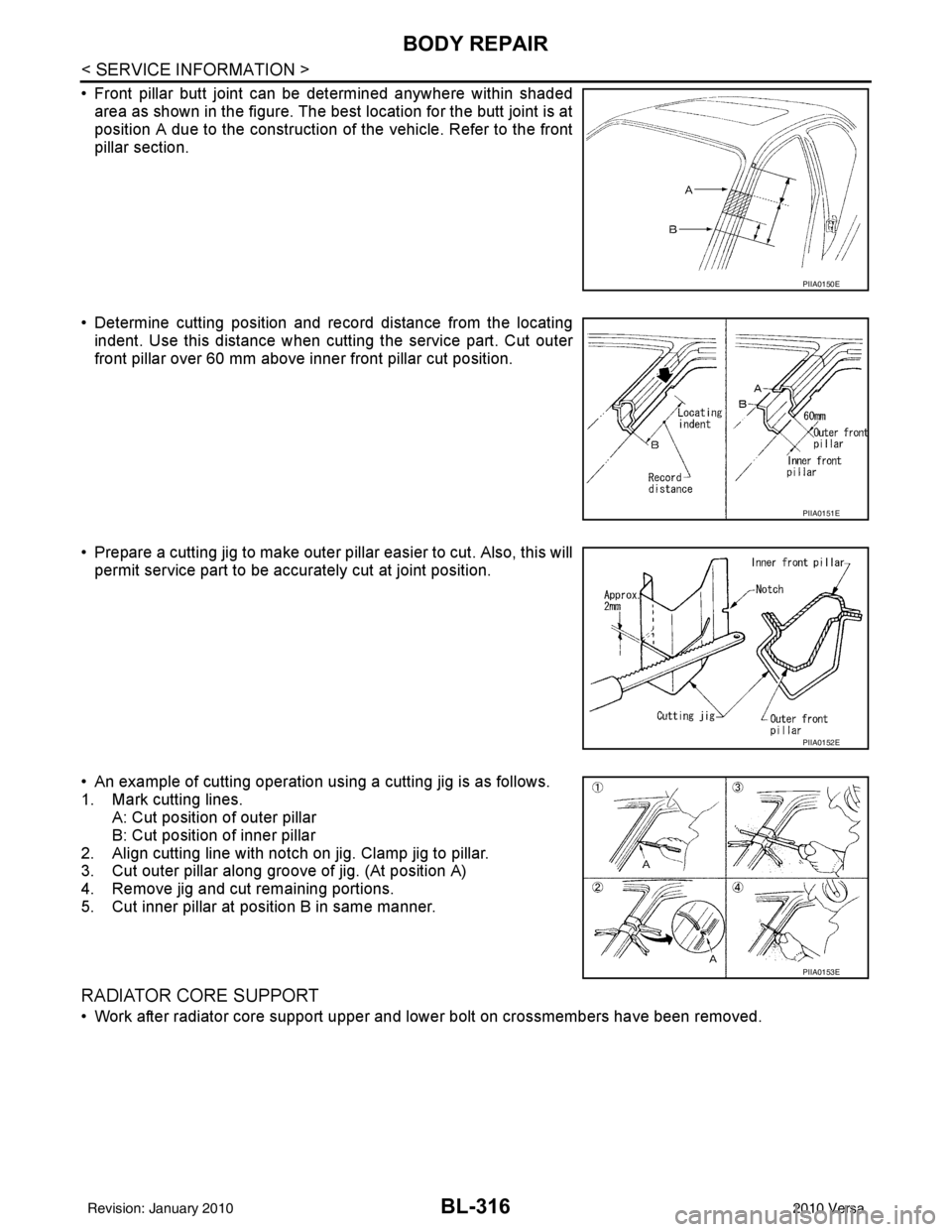
• Front pillar butt joint can be determined anywhere within shadedarea as shown in the figure. The best location for the butt joint is at
position A due to the construction of the vehicle. Refer to the front
pillar section.
• Determine cutting position and record distance from the locating indent. Use this distance when cutt ing the service part. Cut outer
front pillar over 60 mm above inner front pillar cut position.
• Prepare a cutting jig to make outer pillar easier to cut. Also, this will permit service part to be accurately cut at joint position.
• An example of cutting operation using a cutting jig is as follows.
1. Mark cutting lines. A: Cut position of outer pillar
B: Cut position of inner pillar
2. Align cutting line with notch on jig. Clamp jig to pillar.
3. Cut outer pillar along groove of jig. (At position A)
4. Remove jig and cut remaining portions.
5. Cut inner pillar at position B in same manner.
RADIATOR CORE SUPPORT
• Work after radiator core support upper and lower bolt on crossmembers have been removed.
PIIA0150E
PIIA0151E
PIIA0152E
PIIA0153E
Revision: January 20102010 Versa
Page 826 of 3745
BODY REPAIRBL-317
< SERVICE INFORMATION >
C
DE
F
G H
J
K L
M A
B
BL
N
O P
HOODLEDGE LH
• Work after radiator core support upper and lower have been removed.
Change Parts �z Radiator core side support �z Radiator core support upper
LIIA2892E
Revision: January 20102010 Versa
Page 827 of 3745
BL-318
< SERVICE INFORMATION >
BODY REPAIR
HOODLEDGE RH
• Work after radiator core support upper and lower have been removed.
Change Parts�z Hoodledge reinforcement assembly �zFront strut housing �zFender bracket
�z Cowl top side upper �zHoodledge upper �zHoodledge connector
LIIA2893E
Revision: January 20102010 Versa