Page 28 of 3745

PREPARATIONAT-11
< SERVICE INFORMATION >
DE
F
G H
I
J
K L
M A
B
AT
N
O P
PREPARATION
Special Service ToolINFOID:0000000005397214
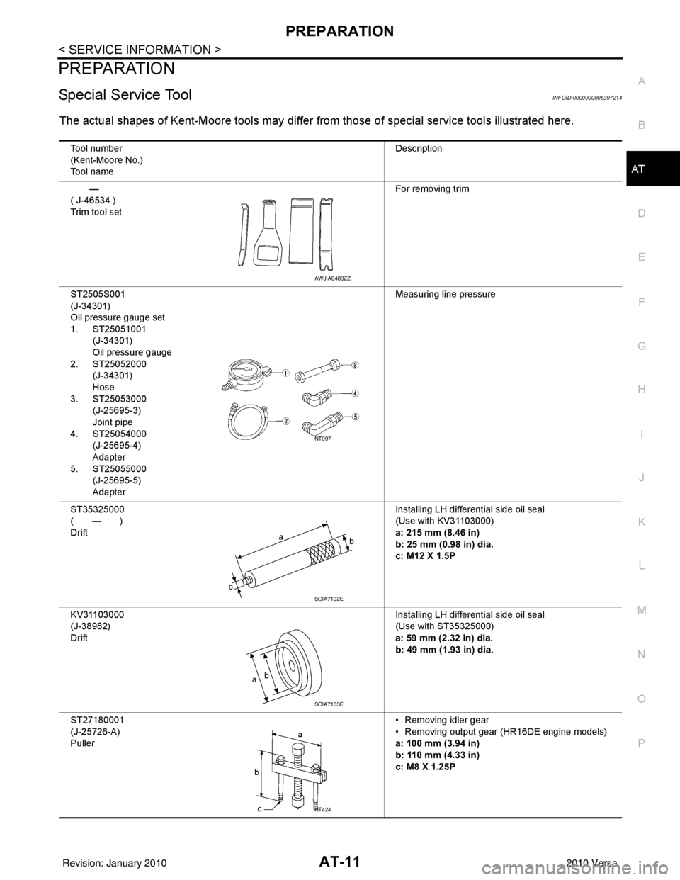
The actual shapes of Kent-Moore tools may differ from those of special service tools illustrated here.
Tool number
(Kent-Moore No.)
Tool name Description
—
( J-46534 )
Trim tool set For removing trim
ST2505S001
(J-34301)
Oil pressure gauge set
1. ST25051001 (J-34301)
Oil pressure gauge
2. ST25052000 (J-34301)
Hose
3. ST25053000 (J-25695-3)
Joint pipe
4. ST25054000 (J-25695-4)
Adapter
5. ST25055000 (J-25695-5)
Adapter Measuring line pressure
ST35325000
( — )
Drift Installing LH differential side oil seal
(Use with KV31103000)
a: 215 mm (8.46 in)
b: 25 mm (0.98 in) dia.
c: M12 X 1.5P
KV31103000
(J-38982)
Drift Installing LH differential side oil seal
(Use with ST35325000)
a: 59 mm (2.32 in) dia.
b: 49 mm (1.93 in) dia.
ST27180001
(J-25726-A)
Puller • Removing idler gear
• Removing output gear (HR16DE engine models)
a: 100 mm (3.94 in)
b: 110 mm (4.33 in)
c: M8 X 1.25P
AWJIA0483ZZ
NT097
SCIA7102E
SCIA7103E
NT424
Revision: January 20102010 Versa
Page 29 of 3745

AT-12
< SERVICE INFORMATION >
PREPARATION
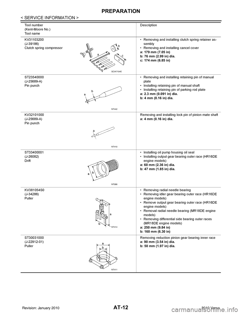
KV31103200
(J-39186)
Clutch spring compressor• Removing and installing clutch spring retainer as-
sembly
• Removing and installing cancel cover
a: 179 mm (7.05 in)
b: 76 mm (2.99 in) dia.
c: 174 mm (6.85 in)
ST23540000
(J-25689-A)
Pin punch • Removing and installing retaining pin of manual
plate
• Installing retaining pin of manual shaft
• Installing retaining pin of parking rod plate
a: 2.3 mm (0.091 in) dia.
b: 4 mm (0.16 in) dia.
KV32101000
(J-25689-A)
Pin punch Removing and installing lock pin of pinion mate shaft
a: 4 mm (0.16 in) dia.
ST33400001
(J-26082)
Drift • Installing oil pump housing oil seal
• Installing output gear bearing outer race (HR16DE
engine models)
a: 60 mm (2.36 in) dia.
b: 47 mm (1.85 in) dia.
KV381054S0
(J-34286)
Puller • Removing radial needle bearing
• Removing idler gear bearing outer race (HR16DE
engine models)
• Remove output gear bearing outer race (HR16DE engine models)
• Removal radial needle bearing (MR18DE engine models)
• Removing differential side bearing outer races
(MR18DE engine models)
a: 250 mm (9.84 in)
b: 160 mm (6.30 in)
ST30031000
(J-22912-01)
Puller Removing reduction pinion gear bearing inner race
a: 90 mm (3.54 in) dia.
b: 50 mm (1.97 in) dia.
Tool number
(Kent-Moore No.)
Tool name
Description
SCIA7104E
NT442
NT410
NT086
NT414
NT411
Revision: January 20102010 Versa
Page 31 of 3745

AT-14
< SERVICE INFORMATION >
PREPARATION
Commercial Service Tool
INFOID:0000000005397215
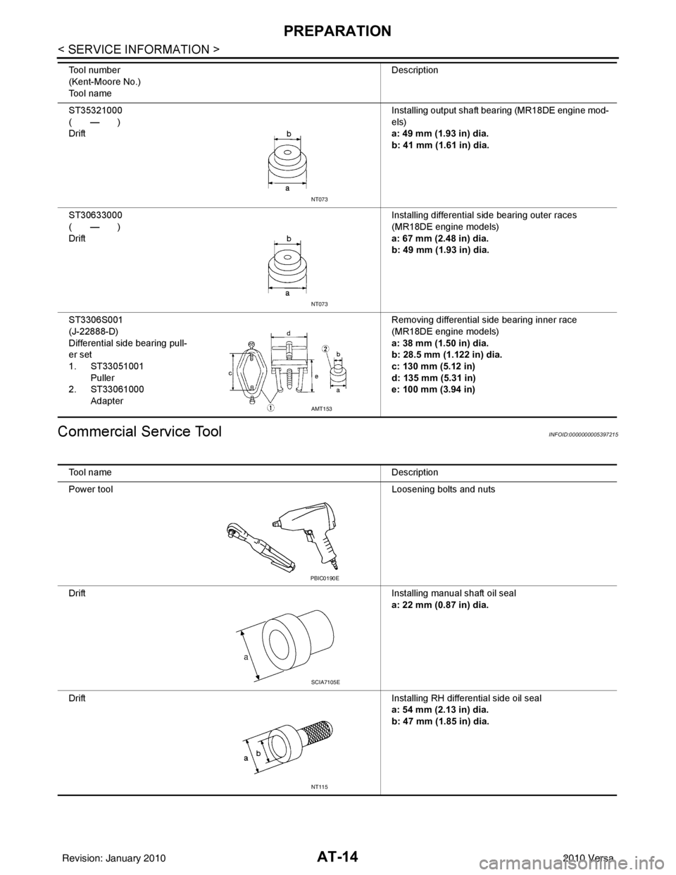
ST35321000
( — )
Drift Installing output shaft bearing (MR18DE engine mod-
els)
a: 49 mm (1.93 in) dia.
b: 41 mm (1.61 in) dia.
ST30633000
( — )
Drift Installing differential side bearing outer races
(MR18DE engine models)
a: 67 mm (2.48 in) dia.
b: 49 mm (1.93 in) dia.
ST3306S001
(J-22888-D)
Differential side bearing pull-
er set
1. ST33051001 Puller
2. ST33061000 Adapter Removing differential side bearing inner race
(MR18DE engine models)
a: 38 mm (1.50 in) dia.
b: 28.5 mm (1.122 in) dia.
c: 130 mm (5.12 in)
d: 135 mm (5.31 in)
e: 100 mm (3.94 in)
Tool number
(Kent-Moore No.)
Tool name
Description
NT073
NT073
AMT153
Tool name
Description
Power tool Loosening bolts and nuts
Drift Installing manual shaft oil seal
a: 22 mm (0.87 in) dia.
Drift Installing RH differential side oil seal
a: 54 mm (2.13 in) dia.
b: 47 mm (1.85 in) dia.
PBIC0190E
SCIA7105E
NT115
Revision: January 20102010 Versa
Page 35 of 3745

AT-18
< SERVICE INFORMATION >
A/T FLUID
5. Run engine at idle speed for 5 minutes.
6. Check A/T fluid level and condition. Refer to AT-17, "
Checking A/T Fluid".
A/T Fluid Cooler CleaningINFOID:0000000005397218
Whenever the A/T is repaired, overhauled, or replaced, the A/T fluid cooler mounted in the radiator must be
inspected and cleaned.
Metal debris and friction material, if present, can becom e trapped in the A/T fluid cooler. This debris can con-
taminate the newly serviced A/T or, in severe cases, can bloc k or restrict the flow of A/T fluid. In either case,
malfunction of the newly serviced A/T may result.
Debris, if present, may build up as A/T fluid enters the c ooler inlet. It will be necessary to back flush the cooler
through the cooler outlet in order to flush out any built up debris.
A/T FLUID COOLER CLEANING PROCEDURE
1. Identify the A/T inlet and outlet fluid cooler hoses.
2. Position an oil pan under the A/T inlet and outlet fluid cooler hoses.
3. Disconnect the A/T fluid cooler inlet and outlet rubber hoses from the steel cooler tubes or bypass valve.
NOTE:
Replace the cooler hoses if rubber material from the hose
remains on the tube fitting.
4. Allow any A/T fluid that remains in the cooler hoses to drain into the oil pan.
5. Insert the extension adapter hose of a can of Transmission
Cooler Cleaner (Nissan P/N 999MP-AM006) into the cooler out-
let hose.
CAUTION:
• Wear safety glasses and rubber gloves when spraying the Transmission Cooler Cleaner.
• Spray Transmission Cooler Cleaner only with adequate
ventilation.
• Avoid contact with eyes and skin.
• Do not breathe vapors or spray mist.
6. Hold the hose and can as high as possible and spray Transmis- sion Cooler Cleaner in a continuous stream into the cooler outlet
hose until A/T fluid flows out of t he cooler inlet hose for 5 seconds.
7. Insert the tip of an air gun into the end of the cooler outlet hose.
8. Wrap a shop rag around the air gun tip and end of cooler outlet hose.
9. Blow compressed air regulated to 5 - 9 kg/cm
2 (490 - 883 kPa, 71 - 128 psi) through the cooler outlet hose
for 10 seconds to force out any remaining A/T fluid.
10. Repeat steps 5 through 9 three additional times.
11. Position an oil pan under the banjo bolts that connec t the A/T fluid cooler steel lines to the A/T.
12. Remove the banjo bolts. Fluid grade and capacity: Refer to
MA-14
.
SCIA5628E
SCIA5629E
SCIA5630E
Revision: January 20102010 Versa
Page 36 of 3745

A/T FLUIDAT-19
< SERVICE INFORMATION >
DE
F
G H
I
J
K L
M A
B
AT
N
O P
13. Flush each steel line from the cooler side back toward the A/T by spraying Transmission Cooler Cleaner in a continuous stream for 5 seconds.
14. Blow compressed air regulated to 5 - 9 kg/cm
2 (490 - 883 kPa, 71 - 128 psi) through each steel line from
the cooler side back toward the A/T for 10 seconds to force out any remaining A/T fluid.
15. Ensure all debris is removed from the steel cooler lines.
16. Ensure all debris is removed from the banjo bolts and fittings.
17. Perform "A/T FLUID COOL ER DIAGNOSIS PROCEDURE".
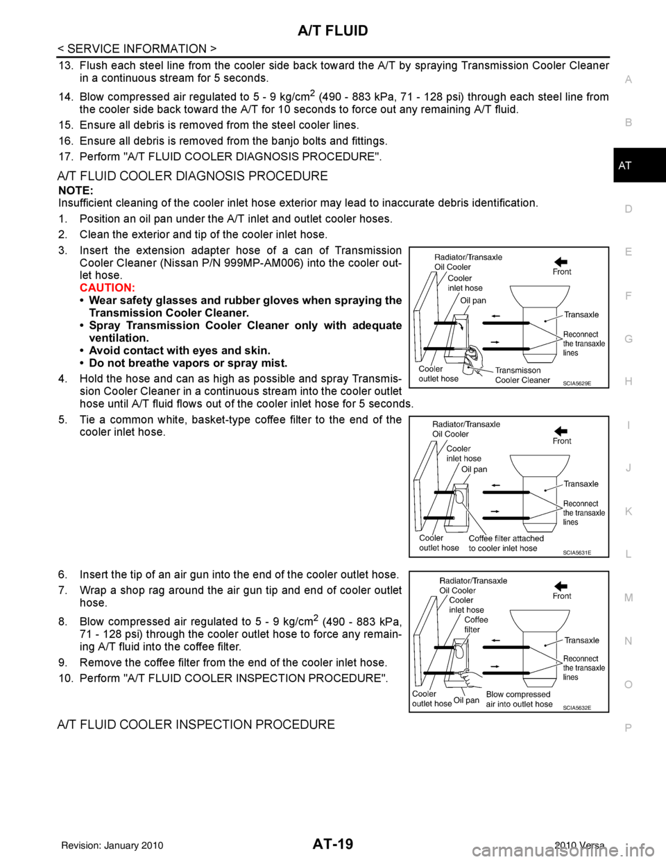
A/T FLUID COOLER DIAGNOSIS PROCEDURE
NOTE:
Insufficient cleaning of the cooler inlet hose exte rior may lead to inaccurate debris identification.
1. Position an oil pan under the A/T inlet and outlet cooler hoses.
2. Clean the exterior and tip of the cooler inlet hose.
3. Insert the extension adapter hose of a can of Transmission Cooler Cleaner (Nissan P/N 999MP-AM006) into the cooler out-
let hose.
CAUTION:
• Wear safety glasses and rubber gloves when spraying the
Transmission Cooler Cleaner.
• Spray Transmission Cooler Cleaner only with adequate
ventilation.
• Avoid contact with eyes and skin.
• Do not breathe vapors or spray mist.
4. Hold the hose and can as high as possible and spray Transmis- sion Cooler Cleaner in a continuous stream into the cooler outlet
hose until A/T fluid flows out of t he cooler inlet hose for 5 seconds.
5. Tie a common white, basket-type coffee filter to the end of the cooler inlet hose.
6. Insert the tip of an air gun into the end of the cooler outlet hose.
7. Wrap a shop rag around the air gun tip and end of cooler outlet hose.
8. Blow compressed air regulated to 5 - 9 kg/cm
2 (490 - 883 kPa,
71 - 128 psi) through the cooler outlet hose to force any remain-
ing A/T fluid into the coffee filter.
9. Remove the coffee filter from the end of the cooler inlet hose.
10. Perform "A/T FLUID COOL ER INSPECTION PROCEDURE".
A/T FLUID COOLER INSPECTION PROCEDURE
SCIA5629E
SCIA5631E
SCIA5632E
Revision: January 20102010 Versa
Page 37 of 3745
AT-20
< SERVICE INFORMATION >
A/T FLUID
1. Inspect the coffee filter for debris.
a. If small metal debris less than 1mm (0.040 in) in size or metalpowder is found in the coffee filter, this is normal. If normal
debris is found, the A/T fluid cooler/radiator can be re-used and
the procedure is ended.
b. If one or more pieces of debris are found that are over 1mm (0.040 in) in size and/or peeled clutch facing material is found in
the coffee filter, the A/T fluid cooler is not serviceable. The A/T
fluid cooler/radiator must be replaced and the inspection proce-
dure is ended. Refer to CO-40, "
Component".
A/T FLUID COOLER FINAL INSPECTION
After performing all procedures, ensure that all remaining oil is cleaned from all components.
SCIA2967E
SCIA5659E
Revision: January 20102010 Versa
Page 38 of 3745
A/T CONTROL SYSTEMAT-21
< SERVICE INFORMATION >
DE
F
G H
I
J
K L
M A
B
AT
N
O P
A/T CONTROL SYSTEM
Cross-Sectional ViewINFOID:0000000005397219
HR16DE engine models
SCIA7651J
1. Converter housing 2. Oil pump3. Brake band
4. Reverse clutch 5. High clutch6. Front planetary gear
7. Low one-way clutch 8. Rear planetary gear9. Forward clutch
10. Overrun clutch 11. Low & reverse brake12. Output gear
13. Band servo piston 14. Reverse clutch drum15. Side cover
16. Idler gear 17. Forward one-way clutch 18. Transaxle case
19. Reduction pinion gear 20. Final gear 21. Differential case
22. Input shaft 23. Torque converter
Revision: January 20102010 Versa
Page 39 of 3745
AT-22
< SERVICE INFORMATION >
A/T CONTROL SYSTEM
MR18DE engine models
Shift MechanismINFOID:0000000005397220
CONSTRUCTION
SCIA7938E
1. Converter housing2. Oil pump3. Brake band
4. Reverse clutch 5. High clutch6. Front planetary gear
7. Low one-way clutch 8. Rear planetary gear9. Forward clutch
10. Overrun clutch 11. Low & reverse brake12. Output gear
13. Band servo piston 14. Reverse clutch drum15. Side cover
16. Idler gear 17. Forward one-way clutch 18. Transaxle case
19. Reduction pinion gear 20. Final gear21. Differential case
22. Input shaft 23. Torque converter
Revision: January 20102010 Versa