2010 NISSAN TIIDA drain bolt
[x] Cancel search: drain boltPage 876 of 3745

BR-28
< SERVICE INFORMATION >
FRONT DISC BRAKE
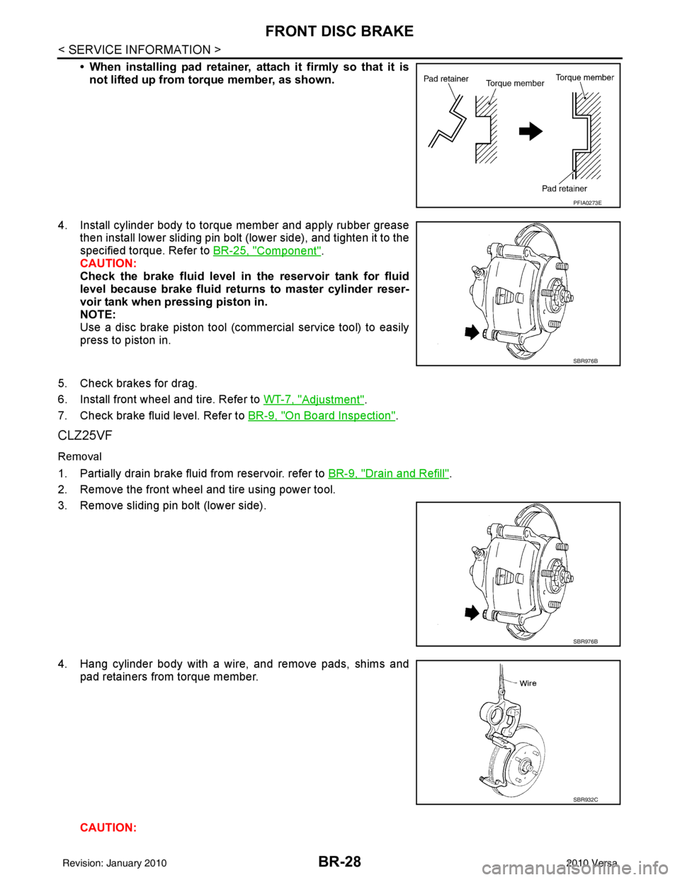
• When installing pad retainer, attach it firmly so that it isnot lifted up from torque member, as shown.
4. Install cylinder body to torque member and apply rubber grease then install lower sliding pin bolt (lower side), and tighten it to the
specified torque. Refer to BR-25, "
Component".
CAUTION:
Check the brake fluid level in the reservoir tank for fluid
level because brake fluid returns to master cylinder reser-
voir tank when pressing piston in.
NOTE:
Use a disc brake piston tool (commercial service tool) to easily
press to piston in.
5. Check brakes for drag.
6. Install front wheel and tire. Refer to WT-7, "
Adjustment".
7. Check brake fluid level. Refer to BR-9, "
On Board Inspection".
CLZ25VF
Removal
1. Partially drain brake fluid from reservoir. refer to BR-9, "Drain and Refill".
2. Remove the front wheel and tire using power tool.
3. Remove sliding pin bolt (lower side).
4. Hang cylinder body with a wire, and remove pads, shims and pad retainers from torque member.
CAUTION:
PFIA0273E
SBR976B
SBR976B
SBR932C
Revision: January 20102010 Versa
Page 878 of 3745

BR-30
< SERVICE INFORMATION >
FRONT DISC BRAKE
Removal and Installation of Brake Caliper Assembly
INFOID:0000000005397000
REMOVAL
1. Remove front wheel and tire.
2. Secure the disc rotor using wheel nuts.
CAUTION:
Put matching marks on wheel hub assembly and disc rotor,
if it is necessary to remove the disc rotor.
3. Drain brake fluid. Refer to BR-9, "
Drain and Refill".
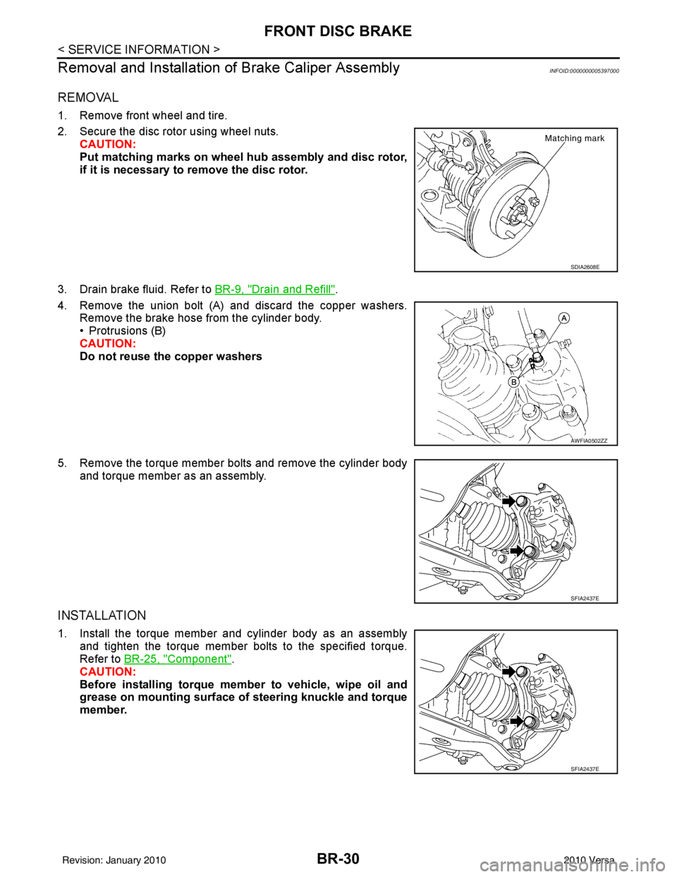
4. Remove the union bolt (A) and discard the copper washers. Remove the brake hose from the cylinder body.
• Protrusions (B)
CAUTION:
Do not reuse the copper washers
5. Remove the torque member bolts and remove the cylinder body and torque member as an assembly.
INSTALLATION
1. Install the torque member and cylinder body as an assemblyand tighten the torque member bolts to the specified torque.
Refer to BR-25, "
Component".
CAUTION:
Before installing torque member to vehicle, wipe oil and
grease on mounting surface of steering knuckle and torque
member.
SDIA2608E
AWFIA0502ZZ
SFIA2437E
SFIA2437E
Revision: January 20102010 Versa
Page 887 of 3745

REAR DRUM BRAKEBR-39
< SERVICE INFORMATION >
C
DE
G H
I
J
K L
M A
B
BR
N
O P
5. Connect the parking brake rear cable to the operating lever.
6. Install the shoe assembly. After assembly, be sure that each part is installed properly. CAUTION:
Do not damage the wheel cylinder piston boot.
7. Install the brake drum.
8. Depress brake pedal for several times (approximately 2 or 3 times).
9. Adjust clearance of brake shoe. Refer to PB-5, "
On-Vehicle Service".
10. Install rear wheel and tire. Refer to WT-7, "
Adjustment".
Removal and Installati on of Wheel CylinderINFOID:0000000005397005
REMOVAL
1. Drain the brake fluid. Refer to BR-9, "Drain and Refill".
2. Remove the rear brake shoe assembly. Refer to BR-36, "
Removal and Installation of Drum Brake Assem-
bly".
3. Remove the bleed valve.
4. Disconnect the brake tube from the wheel cylinder.
5. Remove the wheel cylinder bolts and then remove the wheel cylinder from the back plate.
INSTALLATION
Installation is in the reverse order of removal.
• Tighten bolts and bleed valve to the specified torque. Refer to BR-35, "
Component".
• Refill with new brake fluid and bleed the air. Refer to BR-9, "
Bleeding Brake System".
Disassembly and Assembly of Wheel CylinderINFOID:0000000005397006
DISASSEMBLY
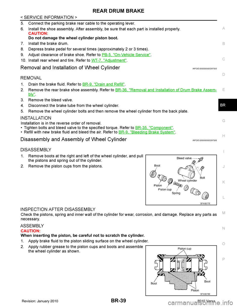
1. Remove boots at the right and left of the wheel cylinder, and pull
the pistons and spring out of the cylinder.
2. Remove the piston cups from the pistons.
INSPECTION AFTER DISASSEMBLY
Check the pistons, spring and inner wall of the cylinder for wear, corrosion, and damage. Replace any parts as
necessary.
ASSEMBLY
CAUTION:
When inserting the piston, be caref ul not to scratch the cylinder.
1. Apply brake fluid to the piston sliding surface on the wheel cylinder.
2. Apply rubber grease to the piston cups and boots and assemble the wheel cylinder as shown.
SFIA3077E
SFIA3078E
Revision: January 20102010 Versa
Page 1000 of 3745
![NISSAN TIIDA 2010 Service Repair Manual CO-18
< ON-VEHICLE REPAIR >[HR16DE]
RADIATOR
Do not remove radiator cap when
the engine is hot. Serious burns could occur from high-pressure
engine coolant escaping from radiator. Wrap a thick cloth NISSAN TIIDA 2010 Service Repair Manual CO-18
< ON-VEHICLE REPAIR >[HR16DE]
RADIATOR
Do not remove radiator cap when
the engine is hot. Serious burns could occur from high-pressure
engine coolant escaping from radiator. Wrap a thick cloth](/manual-img/5/57397/w960_57397-999.png)
CO-18
< ON-VEHICLE REPAIR >[HR16DE]
RADIATOR
Do not remove radiator cap when
the engine is hot. Serious burns could occur from high-pressure
engine coolant escaping from radiator. Wrap a thick cloth around the cap. Slowly turn it a quarter of a
turn to release built-up pressure. Ca refully remove radiator cap by turning it all the way.
REMOVAL
1. Remove engine under cover. Refer to EI-15, "Removal and Installation".
2. Drain engine coolant from radiator. Refer to CO-12, "
Changing Engine Coolant".
CAUTION:
• Perform this step when engine is cold.
• Do not spill engine coolant on drive belt.
3. Remove air duct (inlet). Refer to EM-26, "
Exploded View".
4. Remove reservoir tank as follows:
a. Disconnect reservoir tank hose.
b. Release the tab (A) in the direction shown by the arrow ( ).
c. Lift up while removing the reservoir tank hose, and remove it.
5. Disconnect harness connector from fan motor, and move harness aside.
6. Disconnect A/T fluid cooler hoses if equipped. • Install plug to avoid leakage of A/T fluid if equipped.
7. Remove radiator hoses (upper and lower).
8. Remove radiator core support cover.
9. Remove cooling fan assembly.
10. Remove radiator core support (upper) bolts, bolts of stationary part on the radiator core support side and clip. Lift radiator
assembly (1) from radiator (upper) mount part of radiator core
support (upper) (2).
11. Move radiator assembly (1) to the rearward direction of vehicle, and then lift it upward to remove.
CAUTION:
Do not damage or scratch A/ C condenser if equipped and
radiator core when removing.
INSTALLATION
Installation is in the reverse order of removal.
CAUTION:
Do not damage or scratch A/C condenser if equipped and radiator core when removing.
INSPECTION AFTER INSTALLATION
• Check for leaks of engine coolant. Refer to CO-12, "Inspection".
• Start and warm up engine. Visually check if there is no leaks of engine coolant and A/T fluid if equipped. Refer to CO-12, "
Inspection" and AT-17, "Checking A/T Fluid".
PBIC3800E
PBIC3805E
Revision: January 20102010 Versa
Page 1003 of 3745
![NISSAN TIIDA 2010 Service Repair Manual WATER PUMPCO-21
< ON-VEHICLE REPAIR > [HR16DE]
C
D
E
F
G H
I
J
K L
M A
CO
NP
O
WATER PUMP
Exploded ViewINFOID:0000000005398192
Removal and InstallationINFOID:0000000005398193
REMOVAL
1. Drain engine c NISSAN TIIDA 2010 Service Repair Manual WATER PUMPCO-21
< ON-VEHICLE REPAIR > [HR16DE]
C
D
E
F
G H
I
J
K L
M A
CO
NP
O
WATER PUMP
Exploded ViewINFOID:0000000005398192
Removal and InstallationINFOID:0000000005398193
REMOVAL
1. Drain engine c](/manual-img/5/57397/w960_57397-1002.png)
WATER PUMPCO-21
< ON-VEHICLE REPAIR > [HR16DE]
C
D
E
F
G H
I
J
K L
M A
CO
NP
O
WATER PUMP
Exploded ViewINFOID:0000000005398192
Removal and InstallationINFOID:0000000005398193
REMOVAL
1. Drain engine coolant from radiator. Refer to
CO-12, "Changing Engine Coolant".
CAUTION:
• Perform this step when the engine is cold.
• Never spill engine coolant on drive belts.
2. Partially remove front fender protector (RH). Refer to EI-24, "
Removal and Installation".
3. Loosen mounting bolts of water pump pulley before loosening belt tension of drive belt.
4. Remove drive belt. Refer to EM-15, "
Removal and Installation".
5. Remove water pump pulley.
6. Remove water pump. • Loosen mounting bolts in reverse order as shown.
• Engine coolant will leak from cylinder block, so have a recep-tacle ready below.
CAUTION:
• Handle water pump vane so that it does not contact any other parts.
• Water pump cannot be disassembled and should be replaced as a unit.
INSTALLATION
Installation is in the reverse order of removal.
Water pump.
1. Gasket 2. Water pump3. Water pump pulley
PBIC3807E
KBIA3393J
Revision: January 20102010 Versa
Page 1023 of 3745
![NISSAN TIIDA 2010 Service Repair Manual RADIATORCO-41
< SERVICE INFORMATION > [MR18DE]
C
D
E
F
G H
I
J
K L
M A
CO
NP
O
Removal and InstallationINFOID:0000000005398215
WARNING:
Do not remove radiator cap when the engine is
hot. Serious burn NISSAN TIIDA 2010 Service Repair Manual RADIATORCO-41
< SERVICE INFORMATION > [MR18DE]
C
D
E
F
G H
I
J
K L
M A
CO
NP
O
Removal and InstallationINFOID:0000000005398215
WARNING:
Do not remove radiator cap when the engine is
hot. Serious burn](/manual-img/5/57397/w960_57397-1022.png)
RADIATORCO-41
< SERVICE INFORMATION > [MR18DE]
C
D
E
F
G H
I
J
K L
M A
CO
NP
O
Removal and InstallationINFOID:0000000005398215
WARNING:
Do not remove radiator cap when the engine is
hot. Serious burns could occur from high-pressure
engine coolant escaping from radiator. Wrap a thick cl oth around the cap. Slowly turn it a quarter of a
turn to release built-up pressure. Carefully remove radiator cap by turning it all the way.
REMOVAL
1. Remove engine under cover. Refer to EI-15, "Removal and Installation".
2. Drain engine coolant from radiator. Refer to CO-36, "
Changing Engine Coolant".
CAUTION:
• Perform this step when engine is cold.
• Do not spill engine coolant on drive belt.
3. Remove air duct (inlet). Refer to EM-135
.
4. Remove reservoir tank as follows:
a. Disconnect reservoir tank hose.
b. Release the tab (A) in the direction shown by the arrow ( ).
c. Lift up while removing the reservoir tank hose, and remove it.
5. Disconnect harness connector from fan motor, and move harness aside.
6. Disconnect CVT or A/T fluid cooler hoses if equipped. • Install plug to avoid leakage of CVT or A/T fluid if equipped.
7. Remove radiator hoses (upper and lower).
8. Remove radiator core support cover. Refer to BL-19
.
9. Remove cooling fan assembly.
10. Remove radiator core support (upper) bolts, bolts of stationary part on the radiator core support side and clip. Lift radiator from
radiator (upper) mount part of radiator core support (upper) (2).
11. Move radiator assembly (1) to the rearward direction of vehicle, and then lift it upward to remove.
CAUTION:
Do not damage or scratch A/C condenser if equipped and
radiator core when removing.
INSTALLATION
Installation is in the reverse order of removal.
CAUTION:
Do not damage or scratch A/C condenser if eq uipped and radiator core when installing.
INSPECTION AFTER INSTALLATION
• Check for leaks of engine coolant. Refer to CO-36, "Inspection".
• Start and warm up engine. Visually check for leaks of engine coolant and CVT or A/T fluid if equipped. Refer
to CVT-14
or AT- 1 7.
PBIC3800E
PBIC3805E
Revision: January 20102010 Versa
Page 1049 of 3745
![NISSAN TIIDA 2010 Service Repair Manual CVT-16
< SERVICE INFORMATION >[RE0F08B]
CVT FLUID
3. Disconnect the fluid cooler inlet and outlet rubber hoses from the
steel cooler tubes.
NOTE:
Replace the cooler hoses if rubber material from the h NISSAN TIIDA 2010 Service Repair Manual CVT-16
< SERVICE INFORMATION >[RE0F08B]
CVT FLUID
3. Disconnect the fluid cooler inlet and outlet rubber hoses from the
steel cooler tubes.
NOTE:
Replace the cooler hoses if rubber material from the h](/manual-img/5/57397/w960_57397-1048.png)
CVT-16
< SERVICE INFORMATION >[RE0F08B]
CVT FLUID
3. Disconnect the fluid cooler inlet and outlet rubber hoses from the
steel cooler tubes.
NOTE:
Replace the cooler hoses if rubber material from the hose
remains on the tube fitting.
4. Allow any CVT fluid that remains in the cooler hoses to drain into the oil pan.
5. Insert the extension adapter hose of a can of Transmission
Cooler Cleaner (Nissan P/N 999MP-AM006) into the cooler out-
let hose.
CAUTION:
• Wear safety glasses and rubber gloves when spraying the Transmission Cooler Cleaner.
• Spray Transmission Cooler Cleaner only with adequate
ventilation.
• Avoid contact with eyes and skin.
• Do not breath vapors or spray mist.
6. Hold the hose and can as high as possible and spray Transmis- sion Cooler Cleaner in a continuous stream into the cooler outlet
hose until CVT fluid flows out of the cooler inlet hose for 5 seconds.
7. Insert the tip of an air gun into the end of the cooler outlet hose.
8. Wrap a shop rag around the air gun tip and of the cooler outlet hose.
9. Blow compressed air regulated to 5 to 9 kg/cm
2 (71 to 128 psi)
through the cooler outlet hose for 10 seconds to force out any
remaining CVT fluid.
10. Repeat steps 5 through 9 three additional times.
11. Position an oil pan under the banjo bolts that connect the CVT fluid cooler steel lines to the transaxle.
12. Remove the banjo bolts.
13. Flush each steel line from the cooler side back toward the tran- saxle by spraying Transmission Cooler Cleaner in a continuous stream for 5 seconds.
14. Blow compressed air regulated to 5 to 9 kg/cm
2 (71 to 128 psi) through each steel line from the cooler
side back toward the transaxle for 10 seconds to force out any remaining CVT fluid.
15. Ensure all debris is removed from the steel cooler lines.
16. Ensure all debris is removed from the banjo bolts and fittings.
17. Perform "CVT FLUID COOLER DIAGNOSIS PROCEDURE".
CVT FLUID COOLER DIAGNOSIS PROCEDURE
NOTE:
Insufficient cleaning of the cooler inlet hose exterior may lead to inaccurate debris identification.
1. Position an oil pan under the transaxle's inlet and outlet cooler hoses.
2. Clean the exterior and tip of the cooler inlet hose.
SCIA4421E
SCIA4422E
SCIA4423E
Revision: January 20102010 Versa
Page 2364 of 3745
![NISSAN TIIDA 2010 Service Repair Manual PRECAUTIONSEM-5
< PRECAUTION > [HR16DE]
C
D
E
F
G H
I
J
K L
M A
EM
NP
O
5. When the repair work is completed, return the ignition switch to the
″LOCK ″ position before connecting
the battery cabl NISSAN TIIDA 2010 Service Repair Manual PRECAUTIONSEM-5
< PRECAUTION > [HR16DE]
C
D
E
F
G H
I
J
K L
M A
EM
NP
O
5. When the repair work is completed, return the ignition switch to the
″LOCK ″ position before connecting
the battery cabl](/manual-img/5/57397/w960_57397-2363.png)
PRECAUTIONSEM-5
< PRECAUTION > [HR16DE]
C
D
E
F
G H
I
J
K L
M A
EM
NP
O
5. When the repair work is completed, return the ignition switch to the
″LOCK ″ position before connecting
the battery cables. (At this time, the steering lock mechanism will engage.)
6. Perform a self-diagnosis check of al l control units using CONSULT-III.
Precaution for Procedure without Cowl Top CoverINFOID:0000000005398025
When performing the procedure after removing cowl top cover, cover
the lower end of windshield.
Precaution for Drain CoolantINFOID:0000000005398026
• Drain coolant when engine is cooled.
Precaution for Disconnecting Fuel PipingINFOID:0000000005398027
• Before starting work, make sure no fire or spark producing items are in the work area.
• Release fuel pressure before disassembly.
• After disconnecting pipes, plug openings to stop fuel leakage.
Precaution for Removal and DisassemblyINFOID:0000000005398028
• When instructed to use special service tools, use the spec ified tools. Always be careful to work safely, avoid
forceful or uninstructed operations.
• Exercise maximum care to avoid damage to mating or sliding surfaces.
• Cover openings of engine system with tape or the equiva lent, if necessary, to seal out foreign materials.
• Mark and arrange disassembly parts in an organized way for easy troubleshooting and assembly.
• When loosening nuts and bolts, as a basic rule, start with the one furthest outside, then the one diagonally
opposite, and so on. If the order of loosening is specif ied, do exactly as specified. Power tools may be used
where noted in the step.
Precaution for Inspection, Repair and ReplacementINFOID:0000000005398029
• Before repairing or replacing, thoroughly inspect parts. Inspect new replacement parts in the same way, and
replace if necessary.
Precaution for Assembly and InstallationINFOID:0000000005398030
• Use torque wrench to tighten bolts or nuts to specification.
• When tightening nuts and bolts, as a basic rule, equally tighten in several different steps starting with the ones in center, then ones on inside and outside diagonally in this order. If the order of tightening is specified,
do exactly as specified.
• Replace with new gasket, packing, oil seal or O-ring.
• Thoroughly wash, clean, and air-blow each part. Carefully check oil or coolant passages for any restriction
and blockage.
• Avoid damaging sliding or mating surfaces. Completely remove foreign materials such as cloth lint or dust. Before assembly, oil sliding surfaces well.
• Release air within route after draining coolant.
• Before starting engine, apply fuel pressure to fuel lines with turning ignition switch ON (with engine stopped). Then make sure that there are no leaks at fuel line connections.
• After repairing, start engine and increase engine speed to check coolant, fuel, oil, and exhaust systems for leakage.
PIIB3706J
Revision: January 20102010 Versa