2010 NISSAN TIIDA check engine light
[x] Cancel search: check engine lightPage 3563 of 3745

SC-24
< SERVICE INFORMATION >
CHARGING SYSTEM
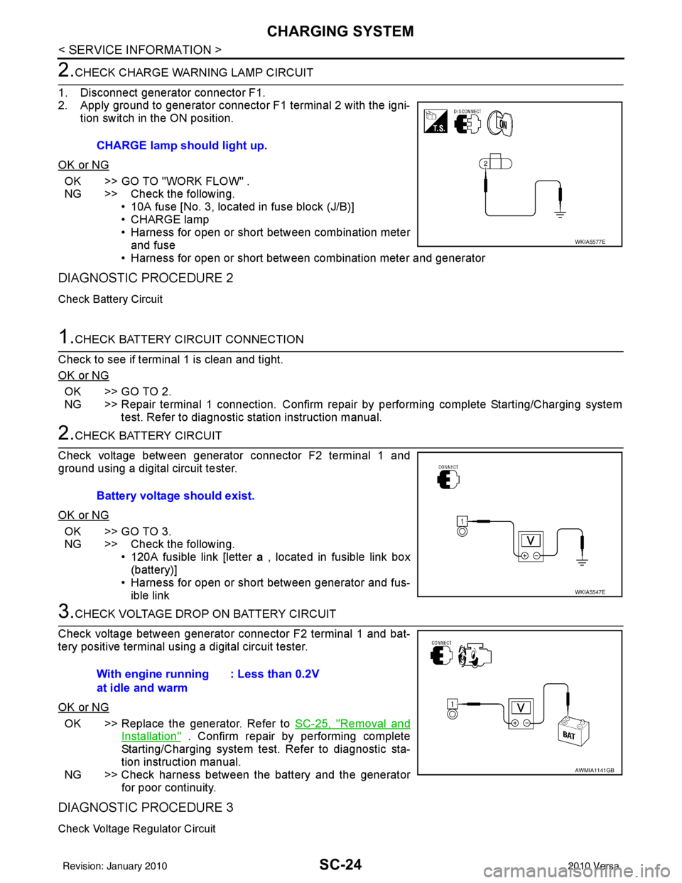
2.CHECK CHARGE WARNING LAMP CIRCUIT
1. Disconnect generator connector F1.
2. Apply ground to generator connector F1 terminal 2 with the igni- tion switch in the ON position.
OK or NG
OK >> GO TO "WORK FLOW" .
NG >> Check the following. • 10A fuse [No. 3, located in fuse block (J/B)]
• CHARGE lamp
• Harness for open or short between combination meterand fuse
• Harness for open or short between combination meter and generator
DIAGNOSTIC PROCEDURE 2
Check Battery Circuit
1.CHECK BATTERY CIRCUIT CONNECTION
Check to see if terminal 1 is clean and tight.
OK or NG
OK >> GO TO 2.
NG >> Repair terminal 1 connection. Confirm repair by performing complete Starting/Charging system test. Refer to diagnostic station instruction manual.
2.CHECK BATTERY CIRCUIT
Check voltage between generator connector F2 terminal 1 and
ground using a digital circuit tester.
OK or NG
OK >> GO TO 3.
NG >> Check the following. • 120A fusible link [letter a , located in fusible link box
(battery)]
• Harness for open or short between generator and fus- ible link
3.CHECK VOLTAGE DROP ON BATTERY CIRCUIT
Check voltage between generator connector F2 terminal 1 and bat-
tery positive terminal using a digital circuit tester.
OK or NG
OK >> Replace the generator. Refer to SC-25, "Removal and
Installation" . Confirm repair by performing complete
Starting/Charging system test. Refer to diagnostic sta-
tion instruction manual.
NG >> Check harness between the battery and the generator for poor continuity.
DIAGNOSTIC PROCEDURE 3
Check Voltage Regulator Circuit
CHARGE lamp should light up.
WKIA5577E
Battery voltage should exist.
WKIA5547E
With engine running
at idle and warm : Less than 0.2V
AWMIA1141GB
Revision: January 20102010 Versa
Page 3572 of 3745

SE-6
< SERVICE INFORMATION >
SQUEAK AND RATTLE TROUBLE DIAGNOSES
If the noise can be duplicated easily during the test drive, to help identify the source of the noise, try to dupli-
cate the noise with the vehicle stopped by doing one or all of the following:
1) Close a door.
2) Tap or push/pull around the area where the noise appears to be coming from.
3) Rev the engine.
4) Use a floor jack to recreate vehicle “twist”.
5) At idle, apply engine load (electrical load, half-clutch on M/T model, drive position on A/T model).
6) Raise the vehicle on a hoist and hit a tire with a rubber hammer.
• Drive the vehicle and attempt to duplicate the conditions the customer states exist when the noise occurs.
• If it is difficult to duplicate the noise, drive the v ehicle slowly on an undulating or rough road to stress the
vehicle body.
CHECK RELATED SERVICE BULLETINS
After verifying the customer concern or symptom, chec k ASIST for Technical Service Bulletins (TSBs) related
to that concern or symptom.
If a TSB relates to the symptom, follo w the procedure to repair the noise.
LOCATE THE NOISE AND IDENTIFY THE ROOT CAUSE
1. Narrow down the noise to a general area.To help pinpoint the source of the noise, use a listening tool
(Chassis Ear: J-39570, Engine Ear: J-39565 and mechanic's stethoscope).
2. Narrow down the noise to a more specific area and identify the cause of the noise by:
• removing the components in the area that you suspect the noise is coming from.
Do not use too much force when removing clips and fasteners, otherwise clips and fasteners can be broken
or lost during the repair, resulting in the creation of new noise.
• tapping or pushing/pulling the component that you suspect is causing the noise.
Do not tap or push/pull the component with excessive force, otherwise the noise will be eliminated only tem-
porarily.
• feeling for a vibration with your hand by touching the component(s) that you suspect is (are) causing the
noise.
• placing a piece of paper between components that you suspect are causing the noise.
• looking for loose components and contact marks. Refer to SE-7, "
Generic Squeak and Rattle Troubleshooting" .
REPAIR THE CAUSE
• If the cause is a loose component, tighten the component securely.
• If the cause is insufficient clearance between components:
- separate components by repositioning or loos ening and retightening the component, if possible.
- insulate components with a suitable insulator such as urethane pads, foam blocks, felt cloth tape or urethane tape. A NISSAN Squeak and Rattle Kit (J-43980) is av ailable through your authorized NISSAN Parts Depart-
ment.
CAUTION:
Do not use excessive force as many components are constructed of plastic and may be damaged.
Always check with the Parts Department for the latest parts information.
The following materials are contained in the NISSAN Squeak and Rattle Kit (J-43980). Each item can be
ordered separately as needed.
URETHANE PADS [1.5 mm (0.059 in) thick]
Insulates connectors, harness, etc.
76268-9E005: 100 ×135 mm (3.94× 5.31 in)/76884-71L01: 60 ×85 mm (2.36 ×3.35 in)/76884-71L02: 15 ×25
mm (0.59× 0.98 in)
INSULATOR (Foam blocks)
Insulates components from contact. Can be used to fill space behind a panel.
73982-9E000: 45 mm (1.77 in) thick, 50 ×50 mm (1.97 ×1.97 in)/73982-50Y00: 10 mm (0.39 in) thick,
50× 50 mm (1.97 ×1.97 in)
INSULATOR (Light foam block)
80845-71L00: 30 mm (1.18 in) thick, 30 ×50 mm (1.18 ×1.97 in)
FELT CLOTH TAPE
Used to insulate where movemen t does not occur. Ideal for instrument panel applications.
68370-4B000: 15 ×25 mm (0.59× 0.98 in) pad/68239-13E00: 5 mm (0.20 in ) wide tape roll. The following
materials not found in the kit can also be used to repair squeaks and rattles.
UHMW (TEFLON) TAPE
Insulates where slight movement is present. Ideal for inst rument panel applications.
Revision: January 20102010 Versa
Page 3647 of 3745

STC-1
STEERING
C
DE
F
H I
J
K L
M
SECTION STC
A
B
STC
N
O P
CONTENTS
STEERING CONTROL SYSTEM
EPS
BASIC INSPECTION ....... .............................
3
DIAGNOSIS AND REPAIR WORKFLOW ..... .....3
Work Flow ........................................................... ......3
SYSTEM DESCRIPTION ..............................5
EPS SYSTEM ... .............................................. .....5
System Diagram .................................................. ......5
System Description ...................................................5
Component Parts Location ........................................6
Component Description .............................................6
DIAGNOSIS SYSTEM (EPS CONTROL UNIT)
.....
8
CONSULT-III Function ........................................ ......8
DTC/CIRCUIT DIAGNOSIS ..........................9
C1601 BATTERY POWER SUPPLY ..................9
Description .......................................................... ......9
DTC Logic .................................................................9
Diagnosis Procedure .................................................9
C1604 TORQUE SENSOR .................................11
Description ..............................................................11
DTC Logic ...............................................................11
Diagnosis Procedure ...............................................11
C1606 EPS MOTOR ...........................................13
Description .......................................................... ....13
DTC Logic ...............................................................13
Diagnosis Procedure ...............................................13
Component Inspection ............................................13
C1607, C1608 EPS CONTROL UNIT ................15
Description .......................................................... ....15
DTC Logic ...............................................................15
Diagnosis Procedure ...............................................15
C1609 VEHICLE SPEED SIGNAL .....................16
Description ........................................................... ....16
DTC Logic ................................................................16
Diagnosis Procedure ...............................................16
C1610 ENGINE STATUS SIGNAL ...................17
Description ...............................................................17
DTC Logic ................................................................17
Diagnosis Procedure ...............................................17
U1000 CAN COMM CIRCUIT ...........................18
Description ...............................................................18
DTC Logic ................................................................18
Diagnosis Procedure ...............................................18
EPS WARNING LAMP ......................................19
Description ...............................................................19
Component Function Check ....................................19
Diagnosis Procedure ...............................................19
ECU DIAGNOSIS INFORMATION ..............20
EPS CONTROL UNIT .......................................20
Reference Value .................................................. ....20
Wiring Diagram - ELECTRONICALLY CON-
TROLLED POWER STEERING SYSTEM - ............
22
Fail-Safe .............................................................. ....23
DTC Inspection Priority Chart ..................................24
DTC Index ...............................................................24
SYMPTOM DIAGNOSIS ..............................25
EPS WARNING LAMP DOES NOT TURN ON ...25
Description ........................................................... ....25
Diagnosis Procedure ...............................................25
EPS WARNING LAMP DOES NOT TURN
OFF ....................................................................
26
Description ...............................................................26
Diagnosis Procedure ...............................................26
STEERING WHEEL TURNING FORCE IS
HEAVY OR LIGHT ............................................
27
Revision: January 20102010 Versa
Page 3673 of 3745
![NISSAN TIIDA 2010 Service Repair Manual STEERING WHEEL TURNING FORCE IS HEAVY OR LIGHTSTC-27
< SYMPTOM DIAGNOSIS > [EPS]
C
D
E
F
H I
J
K L
M A
B
STC
N
O P
STEERING WHEEL TURNING FO RCE IS HEAVY OR LIGHT
DescriptionINFOID:0000000005600199
St NISSAN TIIDA 2010 Service Repair Manual STEERING WHEEL TURNING FORCE IS HEAVY OR LIGHTSTC-27
< SYMPTOM DIAGNOSIS > [EPS]
C
D
E
F
H I
J
K L
M A
B
STC
N
O P
STEERING WHEEL TURNING FO RCE IS HEAVY OR LIGHT
DescriptionINFOID:0000000005600199
St](/manual-img/5/57397/w960_57397-3672.png)
STEERING WHEEL TURNING FORCE IS HEAVY OR LIGHTSTC-27
< SYMPTOM DIAGNOSIS > [EPS]
C
D
E
F
H I
J
K L
M A
B
STC
N
O P
STEERING WHEEL TURNING FO RCE IS HEAVY OR LIGHT
DescriptionINFOID:0000000005600199
Steering wheel turning force is heavy or light.
Diagnosis ProcedureINFOID:0000000005600200
1.CHECK THE ILLUMINATION OF THE EPS WARNING LAMP
Check that the EPS warning lamp turns ON when igni tion switch turns ON. Then, EPS warning lamp turns
OFF after the engine is started.
Is the inspection result normal?
YES >> GO TO 4.
NO >> GO TO 2.
2.PERFORM SELF-DIAGNOSIS
With CONSULT-III
1. Turn the ignition switch OFF to ON.
2. Perform EPS control unit self-diagnosis.
Is any DTC detected?
YES >> Check the DTC. Refer to STC-24, "DTC Index".
NO >> GO TO 3.
3.CHECK EPS CONTROL UNIT SIGNAL
With CONSULT-III
1. Start the engine. CAUTION:
Stop the vehicle.
2. Turn steering wheel from full left stop to full right stop.
3. Select “TORQUE SENSOR” of “DATA MONITOR” for EPS control unit.
Is the inspection result normal?
YES >> GO TO 5.
NO >> GO TO 4.
4.CHECK EPS MOTOR
Perform the trouble diagnosis of EPS motor. Refer to STC-13, "
Diagnosis Procedure".
Is the inspection result normal?
YES >> GO TO 5.
NO >> Repair or replace the specific malfunctioning part.
5.CHECK STEERING WH EEL TURNING FORCE
Check the steering wheel turning force. Refer to PS-6, "
On-Vehicle Inspection and Service".
Is the inspection result normal?
YES >> Inspection End
NO >> Check the steering wheel turning force for mechanical malfunction. Refer to PS-6, "
On-Vehicle
Inspection and Service".
Monitor item ConditionDisplay value
TORQUE SENSOR Steering wheel: Not steer-
ing (There is no steering
force)
Approx. 0 Nm
Steering wheel: Right turn Positive value (Nm)
Steering wheel: Left turn Negative value (Nm)
Revision: January 20102010 Versa