2010 NISSAN QASHQAI battery replacement
[x] Cancel search: battery replacementPage 62 of 297
Downloaded from www.Manualslib.com manuals search engine For more information, see “Seat belts” in the
“1. Safety — seats, seat belts and supplemental
restraint system” section
j4 Ignition knob warning (Intelligent Key
models)
The warning appears when the ignition knob is left
in the Acc or “OFF” position instead of completely
being turned to the LOCK position.
If this warning appears, turn the ignition knob to the
LOCK position.
When the ignition knob is in the ON position, a
buzzer will sound twice and the ignition knob warn-
ing shows when the ignition knob is turned to the
Acc or “OFF” position. This is to warn the driver that
the ignition knob is not in the LOCK position.
MT models:
Depress the ignition PUSH release button and turn
the ignition knob to the LOCK position.
AT or CVT models:
Make sure the gear selector lever is in the P (Park)
position and then turn the ignition switch to the
LOCK position.
See “Ignition knob (where fitted)” in the “5. Starting
and driving” section for further details.
CAUTION
The steering wheel can only be locked when
the ignition knob is in the LOCK position. Make
sure the ignition knob is in the LOCK position
before leaving the vehicle.
The emergency key can only be removed at
the LOCK position. Make sure the ignition
knob is in the LOCK position before removing
the emergency key.
See “Steering lock” in the “5. Starting and driving”
section for further details.
j5 Steering wheel lock warning
The warning appears when the ignition knob is
pressed, but not turned to the Acc or “OFF” posi-
tion within a short period. Move the steering wheel
to release the lock and turn the ignition knob to Acc
or ON. The warning will turn off in approximately 5
seconds.
See “Steering lock” in the “5. Starting and driving”
section for further details.
j6 Brake/Clutch warning (where fitted)
When starting your vehicle, it is necessary to oper-
ate the brake (CVT and AT models) or clutch pedal
(MT models).
For more information, see “Starting the engine” in
the “5. Starting and driving” section.
j7 Handbrake reminder
The reminder will come on if the handbrake is on
whilst the vehicle is being driven.
A buzzer will also sound.
j8 Intelligent Key detection warning
If the Intelligent Key is taken outside of the vehicle
ID recognition zone while the ignition knob is in the
Acc or ON position, the Intelligent Key detection
warning will be displayed and a buzzer will sound.
The Intelligent Key detection warning disappears
when the Intelligent Key is placed back in the pas-
senger compartment.
The message also appears when you try to start the
vehicle if the Intelligent Key is not detected within
the vehicle.
For more information, see “Integrated keyfob/re-
mote control system” in the “3. Pre-driving checks
and adjustments” section.
j9 Intelligent Key low battery warning
The Intelligent Key low battery warning may show if
a low battery voltage is detected when the ignition
knob is turned from “OFF” to the ON position.
For more information, see “Integrated keyfob/Intel-
ligent Key battery replacement” in the “8. Mainte-
nance and do-it-yourself” section.
j10Intelligent Key system fault warning
CAUTION
If the Intelligent Key system fault warning comes
on, it may indicate a system malfunction. We rec-
ommend that you contact a NISSAN dealer or
qualified workshop for repair.
Instruments and controls2-13
Page 91 of 297
Downloaded from www.Manualslib.com manuals search engine use of additional remote controllers, contact a
NISSAN dealer or qualified workshop.
The integrated keyfob will not function under the fol-
lowing conditions:
When the distance between the integrated key-
fob and vehicle is more than approximately 5 m
(15 ft).
When the integrated keyfob battery is
discharged.
When the key is in the ignition switch.
All doors can be locked or unlocked from the out-
side by pressing the “LOCK”
or “UNLOCK”button on the integrated keyfob.
For Super Lock system models only (RHD mod-
els):
When the vehicle is occupied, never lock the
doors with the integrated keyfob. Doing so will
trap the occupants, since the Super Lock system
prevents the doors from being opened from the
inside.
WARNING
Only operate the integrated keyfob lock button in
full and clear view of the vehicle to prevent any-
body being trapped inside the vehicle.
CAUTION
When locking the doors using the integrated
keyfob, be sure not to leave the key in the
vehicle.
Always remove the ignition key or Intelligent
Key, close all windows before operating the
keyfob door lock system.
Ensure that the driver’s door is securely
closed before operating the integrated keyfob
door lock system for correct operation of the
system.
Do not allow the integrated keyfob, which
contains electrical components, to come into
contact with water or salt water. This could
affect the system function.
Do not drop the integrated keyfob.
Do not strike the integrated keyfob sharply
against another object.
Do not place the integrated keyfob for an ex-
tended period in an area where temperatures
exceed 60°C (140°F).
If a integrated keyfob is lost or stolen, NISSAN rec-
ommends erasing the ID code of that integrated
keyfob from the vehicle. This may prevent the unau-
thorised use of the integrated keyfob to unlock the
vehicle. For information regarding the erasing pro-
cedure, contact a NISSAN dealer or qualified work-
shop.
For information regarding the replacement of a bat-
tery, see “Battery” in the “8. Maintenance and
do-it-yourself” section.
SWITCHING FROM CONVENIENCE
MODE TO ANTI-HIJACK MODE
Selective unlock or “Anti-hijack” mode allows the
remote unlocking of only the driver’s door to prevent
an attacker from entering the vehicle via an unlocked
passenger door.
As default, the unlock mode will be set to “Conve-
nience” mode (all doors will unlock). Follow the in-
structions below to switch between convenience
mode and anti-hijack mode.
jA Key with integrated keyfob (from
outside the vehicle)
1. Turn the ignition switch to the “OFF” position.
2. Press and hold both the “LOCK”
and “UN-
LOCK”buttons for 5 seconds.
Setting anti-hijack mode:
– The direction indicators flash once.
Setting convenience mode:
– The direction indicators flash three times.
jB Intelligent Key
1. Turn the ignition switch from ON to LOCK and
exit the vehicle.
2. From outside the vehicle, lock the vehicle using the integrated keyfob “LOCK” button
.
3. Press and hold both the “LOCK”
and “UN-
LOCK”buttons for 10 seconds.
4. Within 3 seconds, press and hold the driver’s
3-4Pre-driving checks and adjustments
Page 93 of 297
![NISSAN QASHQAI 2010 Owners Manual Downloaded from www.Manualslib.com manuals search engine – The message [Single door unlock] appears inthe vehicle information display.
– Only the driver’s door unlocks.
– The direction indicat NISSAN QASHQAI 2010 Owners Manual Downloaded from www.Manualslib.com manuals search engine – The message [Single door unlock] appears inthe vehicle information display.
– Only the driver’s door unlocks.
– The direction indicat](/manual-img/5/56766/w960_56766-92.png)
Downloaded from www.Manualslib.com manuals search engine – The message [Single door unlock] appears inthe vehicle information display.
– Only the driver’s door unlocks.
– The direction indicators flash twice, quickly.
2. Push the “UNLOCK” button
on the integrated
keyfob again.
– All doors unlock.
– The direction indicators flash twice.
Auto-relock:
An auto-relock function will operate 2 minutes after
a full or partial unlock, if no further user action is
taken. The auto-relock will be cancelled if any door
is opened or the key is inserted into the ignition.
KEYFOB OPERATION FAILURE
The keyfob may not work properly if:
The keyfob battery is low. See “Integrated key-
fob/Intelligent Key battery replacement” in the
“8. Maintenance and do-it-yourself” section for
keyfob battery replacement instructions and the
required battery type.
The locking/unlocking system has been used
continuously. An anti lock-abuse system pre-
vents the lock motors from overheating and dis-
ables the keyfob locking operation for a short
period of time if the system is used continuously.
The door handle is being pulled while the
keyfob is being operated.
The vehicle’s battery is dead. NOTE
See Intelligent Key detection warning, Intelligent
Key low battery warning or Intelligent Key system
fault warning in “Vehicle information display” ear-
lier in this section for more information.
The Intelligent Key system is a convenient keyless
entry system that allows you to operate your vehicle
without using an actual key.
WARNING
Radio waves could adversely affect electric medi-
cal equipment. Those who use a pacemaker
should contact the electric medical equipment
manufacturer for the possible influences before
use.
INTELLIGENT KEY OPERATING
RANGE
The Intelligent Key functions can only be used when
the Intelligent Key is within the specified operating
range from the request switch
j1.
When the Intelligent Key battery is discharged or
strong radio waves are present near the operating
location, the Intelligent Key system’s operating
range becomes narrower, and the Intelligent Key
may not function properly.
NPA1042NPA1018
INTELLIGENT KEY SYSTEM
(where fitted)
3-6Pre-driving checks and adjustments
Page 97 of 297
Downloaded from www.Manualslib.com manuals search engine The driver’s door can be locked/unlocked from out-
side using the key/emergency key if the vehicle’s
battery is dead.
To lock the door, insert the key into the driver’s door
key cylinder and turn it towards the front of the ve-
hicle
j1.
To unlock the door, turn the key towards the rear of
the vehicle
j2.
See “Ignition knob (where fitted)” in the “5. Starting
and driving” section for instructions on accessing
the Intelligent Key system Emergency key.
CAUTION
The alarm system will be triggered when the door
is opened using the key (NISSAN alarm equipped
models). To stop the alarm, turn the ignition key
to the ON position or press the unlock
button
on the integrated keyfob.
Initialising the system after vehicle
battery loading or replacement
After recharging or replacing the battery, you should
release (initialise) the system by:
Inserting the key into the ignition switch and then
turning it to the ON position.
Unlocking the vehicle using the integrated key-
fob.
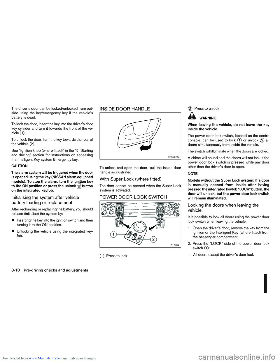
INSIDE DOOR HANDLE
To unlock and open the door, pull the inside door
handle as illustrated.
With Super Lock (where fitted)
The door cannot be opened when the Super Lock
system is activated.
POWER DOOR LOCK SWITCH
j
1 Press to lock
j2Press to unlock
WARNING
When leaving the vehicle, do not leave the key
inside the vehicle.
The power door lock switch, located on the centre
console, can be used to lock
j1 or unlockj2all
doors simultaneously from inside the vehicle.
The switch will illuminate when the doors are locked.
A chime will sound and the doors will not lock if the
power door lock switch is pressed while any door
other than the driver’s door is open.
NOTE
Models without the Super Lock system: If a door
is manually opened from inside after having
pressed the integrated keyfob “LOCK” button, the
door will unlock, but the power door lock switch
will remain illuminated.
Locking the doors when leaving the
vehicle
It is possible to lock all doors using the power door
lock switch when leaving the vehicle:
1. Open the driver’s door, remove the key from the ignition or the Intelligent Key (where fitted) from
the passenger compartment.
2. Press the “LOCK” side of the power door lock switch
j1.
– All doors except the driver’s door lock
SPA2531Z
NPA952
3-10Pre-driving checks and adjustments
Page 132 of 297
Downloaded from www.Manualslib.com manuals search engine Band select button
Press the button to change the reception
wave band as follows:
FM1 →FM 2 →FM T →MW →LW →FM1
When button is pressed while the igni-
tion switch is in the Acc or ON position, the radio
will come on at the last received radio station. If the
CD is already playing, pressing the but-
ton will switch off the CD play mode and the last
received radio station will be selected.
FM Auto store
When the button is pressed for more
than 1.5 seconds and the six strongest stations are
stored in the preset (1 to 6) of the FM T band. Dur-
ing the search, a notification message [AU-
TOSTORE] appears in the display and the sound is
muted until the operation is complete. Once com-
pleted, the radio selects preset 1.
Manual tuning buttons
WARNING
The radio should not be tuned while driving in
order for full attention to be given to the driving
operation.
Press the
orbutton repeatedly to in-
crease or decrease the frequency. The frequency increases or decreases in steps of
100 kHz on the FM band, 9kHz on the MW band,
and 3 kHz on the LW band.
If the
orbutton is held down with a long
press, the frequency will continuously increase or
decrease until the button is released.
SEEK tuning buttons
Pressing briefly on theorbutton starts the
tuning mode. The radio tuner seeks from low to high
or high to low frequencies and stops at the next
broadcasting station. During seek mode, the audio
output is muted. If no broadcasting station can be
found within the complete band cycle, it will return
to the initial frequency.
If the
orbutton is held down with a long
press, the seek mode will continuously increase or
decrease until the button is released. When the but-
ton is released, the seek mode will seek the next
broadcasting station.
Preset station buttonsj1j2j3j4j5j6
Pressing a preset button for less than 2 seconds will
select the stored radio station.
Pressing a preset button for more than 2 seconds
will cause the station currently being received to be
stored against that preset button.
Eighteen stations can be stored in the FM band.
(Six each for FM1, FM2 and FMT)
Six stations can be set for both the MW and LW
bands. If the battery is disconnected, or if the fuse blows,
the radio memory will be erased. In that case, reset
the desired stations after battery connection or fuse
replacement.
Radio data system (RDS) operation
The RDS is a system through which encoded digital
information is transmitted by FM radio station in ad-
dition to the normal FM-radio broadcasting. The
RDS provides information services such as station
name, traffic information and news.
NOTE
In some countries or regions, some of these ser-
vices may not be available.
Alternative Frequency (AF) mode:
The AF mode operates in the FM (radio) mode.
The AF mode operates both in the FM (radio)
and CD mode (if FM was previously selected in
the radio mode).
When AF mode has been set to the “ON” posi-
tion in the user set up menu mode, the [AF] indi-
cator comes on. For activation or deactivation
details, see “MENU button” later in this section.
The AF function compares signal strengths and se-
lects the station with the optimum reception condi-
tions for the currently tuned-in station.
Display screen, heater and air conditioner, and audio system4-25
Page 140 of 297

Downloaded from www.Manualslib.com manuals search engine Eighteen stations can be stored in the FM band.
(Six each for FM1, FM2 and FMT)
Six stations can be set for the AM band.
If the battery is disconnected, or if the fuse blows,
the radio memory will be erased. In that case, reset
the desired stations after battery connection or fuse
replacement.
Radio data system (RDS) operation
The RDS is a system through which encoded digital
information is transmitted by FM radio stations in
addition to the normal FM radio broadcasting. The
RDS provides information services such as station
name, traffic information, or news.
NOTE
In some countries or regions, some of these ser-
vices may not be available.
Alternative Frequency (AF) mode:
The AF mode operates in the FM (radio) mode.
The AF mode operates in the FM (radio), AUX or
CD mode (if FM was previously selected in the
radio mode).
The AF function compares signal strengths and
selects the station with the optimum reception
conditions for the currently tuned-in station.
RDS functions
Programme Service (PS) function (station name
display function):
When an RDS station is tuned in with seek or manual
tuning, the RDS data is received and the PS name
is displayed.
TA Traffic announcement
This function operates in FM (Radio), CD or AUX
mode.
Pressing the
The TA indicator is displayed while TA mode is
on.
When
switched off and the TA indicator will disappear
from the display.
Traffic announcement interrupt function:
When a traffic announcement is received, the an-
nouncement is tuned in and the display shows a
notification message with the radio station name e.g.
[TA: Radio 1].
Once the traffic announcement has finished, the unit
returns to the source that was active before the traf-
fic announcement started.
If
the traffic announcement interrupt mode is can-
celled. The TA mode returns to the standby mode
and the audio unit returns to the previous source.
SETUP BUTTON
To configure Audio, Clock, Bluetooth, Language or
Scroll direction settings, perform the following pro-
cedure:
1. Press the
2. Turn the
clockwise, the display will appear in the following
order:
[Audio] ⇔[Clock] ⇔[Bluetooth] ⇔[Language]
⇔ [Scroll Direction]
After the desired levels have been set, press either
the
(Back) button repeatedly, the
button, or wait for 8 seconds without pressing any
buttons to exit the menu screen.
Display brightness (Day/Night mode)
Press the
switch the display brightness between the daytime
and nighttime mode.
Audio adjustments
Press the
screen then select [Audio].
Each time the
will change as follows:
[Bass] →[Treble] →[Balance] →[Fade] →[AUX
VOL] →[SPD VOL] →setup menu screen [Audio]
→ [Bass]
Display screen, heater and air conditioner, and audio system4-33
Page 218 of 297
Downloaded from www.Manualslib.com manuals search engine 6. Open the bonnet. For details, see “Bonnetrelease” in the “3. Pre-driving checks and
adjustments” section.
7. Remove the vent caps (where fitted) on the bat- tery and cover the battery with an old cloth.
8. Connect the jump leads in the sequence (
j1 →j2→j3→j4 ) as illustrated.
CAUTION
Always connect positivej+ to positivej+
and negativej- to body ground (for ex-
ample, engine lift bracket, etc.) – not to
the battery’s negative
j-.
An incorrect connection could damage the
charging system.
Be sure that the jumper cables do not
touch moving parts in the engine compart-
ment.
Be careful not to allow contact between
the positive jump lead connector and the
vehicle or the negative lead during con-
nection and disconnection.
9. Start the engine of the other vehicle
jA and let it
run for a few minutes. Keep the engine speed at
about 2,000 rpm.
10. Start the engine of your vehicle
jB in the nor-
mal way. CAUTION
Do not keep the starter motor engaged for
more than 10 seconds. If the engine does not
start immediately, turn the ignition switch to
“OFF” and wait 10 seconds before trying
again.
11. After starting the engine of your vehicle, care- fully disconnect the negative lead and then the
positive lead (
j4→j3→j2→j1).
12. Remove and dispose of the cloth that was used to cover the vent holes as it may be contami-
nated with corrosive acid.
13. Install the vent caps (where fitted).
14. Close the bonnet.
NOTE
For models which incorporate the Stop/Start
System:
Ensure that the battery fitted is the special
battery that is enhanced with regard to the
charge-discharge capacity and life perfor-
mance. Avoid using any other battery for the
Stop/Start System, as this may cause early
deterioration of the battery or a malfunction
of the Stop/Start System. It is recommended
that a Genuine NISSAN battery is fitted. For
more information, contact a NISSAN dealer or
qualified workshop
If the battery terminal is disconnected (for bat-
tery replacement, etc.) and then reconnected,
there may be some delay before the Stop/
Start System reactivates.
In case of emergency6-11
Page 231 of 297

Downloaded from www.Manualslib.com manuals search engine 8Maintenance and do-it-yourself
Maintenance and do-it-yourself
Maintenance requirements ....................................... 8-2
Scheduled maintenance...................................... 8-2
General maintenance .......................................... 8-2
Where to go for service ...................................... 8-2
General maintenance ............................................... 8-2 Explanation of general maintenance items ........... 8-2
Maintenance precautions ......................................... 8-4
Engine compartment ................................................ 8-5
Engine cooling system ............................................. 8-6 Checking engine coolant level............................. 8-6
Changing engine coolant .................................... 8-6
Engine oil................................................................. 8-8 Checking engine oil level .................................... 8-8
Changing engine oil ............................................ 8-9
Changing engine oil filter .................................... 8-11
Protect the environment ...................................... 8-13
Fuel filter (Diesel engine models) ............................. 8-13 Draining water .................................................... 8-13
Bleeding the fuel system ..................................... 8-14
Automatic transmission fluid (ATF) ........................... 8-14
Continuously variable transmission (CVT) fluid ......... 8-14
Brakes ..................................................................... 8-15 Checking brake pedal......................................... 8-15
Checking handbrake........................................... 8-15
Brake and clutch fluid .............................................. 8-15
Window washer fluid/headlight cleaner fluid
(where fitted) ........................................................... 8-16
Battery..................................................................... 8-17 Vehicle battery .................................................... 8-17
Jump-starting ...................................................... 8-19 Integrated keyfob/Intelligent Key battery
replacement........................................................ 8-19
Drive belts ............................................................... 8-21
Spark plugs (Petrol engine models).......................... 8-21
Air cleaner filter........................................................ 8-21 Viscous paper type ............................................. 8-22
Dry paper type (where fitted) .............................. 8-22
Wiper blades ........................................................... 8-22 Cleaning ............................................................. 8-22
Front window wiper replacement ........................ 8-22
Back door window wiper replacement ................ 8-23
Windscreen washer nozzle ................................. 8-23
Fuses ...................................................................... 8-23 Passenger compartment ..................................... 8-23
Engine compartment ........................................... 8-24
Lights ...................................................................... 8-25 Headlights .......................................................... 8-25
Exterior lights ...................................................... 8-27
Interior lights....................................................... 8-27
Light locations .................................................... 8-27
Wheels and tyres ..................................................... 8-31 Tyre inflation pressure......................................... 8-31
Types of tyres ..................................................... 8-31
Snow chains....................................................... 8-32
Tyre rotation ....................................................... 8-32
Tyre wear and damage ....................................... 8-33
Tyre age ............................................................. 8-33
Changing tyres and wheels ................................. 8-33
Four-wheel drive (4WD) models ......................... 8-33
Wheel balance.................................................... 8-33