2010 NISSAN QASHQAI battery
[x] Cancel search: batteryPage 164 of 297
Downloaded from www.Manualslib.com manuals search engine Operating precautions ........................................ 5-35
Tyre pressure ..................................................... 5-36
Safety chains ...................................................... 5-36
Trailer brakes...................................................... 5-36
Trailer detection (where fitted) ............................ 5-36
Installation of coupling device ............................. 5-36
Vehicle security........................................................ 5-38
Power steering system............................................. 5-38
Brake system ........................................................... 5-39 Brake precautions .............................................. 5-39
Anti-lock Braking System (ABS).......................... 5-39 Electronic Stability Programme (ESP) system
(where fitted) ........................................................... 5-40
Electronic Stability Programme (ESP) OFF
switch................................................................. 5-42
Cold weather driving................................................ 5-42 Battery ............................................................... 5-43
Engine coolant .................................................... 5-43
Tyre equipment ................................................... 5-43
Special winter equipment.................................... 5-43
Corrosion protection ........................................... 5-43
Page 170 of 297
Downloaded from www.Manualslib.com manuals search engine unlock the steering wheel, insert the ignition key and
turn it gently while rotating the steering wheel slightly
right and left.
The ignition key can only be removed when the
switch is in the LOCK position (Normal parking po-
sition) (0).
AUTOMATIC TRANSMISSION OR
CONTINUOUSLY VARIABLE
TRANSMISSION
On Automatic Transmission (AT) or Continuously
Variable Transmission (CVT) models, the ignition
lock is designed so that the key cannot be turned to
LOCK and removed until the selector lever is moved
to the P (Park) position.
When removing the key from the LOCK position of
the ignition switch, make sure that the selector lever
is in the P (Park) position.
The selector lever can only be moved from the P
(Park) position when the ignition switch is in the ON
position and the footbrake pedal is depressed.
To remove the key from the ignition switch:
1. Move the selector lever into the P (Park) posi-tion.
2. Turn the key to the LOCK position.
3. Remove the key from the ignition switch.
If the key is removed from the ignition switch, the
selector lever cannot be moved from the P (Park)
position. When the key cannot be turned toward the LOCK
position, proceed as follows to remove the key:
1. Move the selector lever into the P (Park) posi-
tion.
2. Turn the key slightly in the ON direction.
3. Turn the key towards the LOCK position.
4. Remove the key.
STEERING LOCK
To lock the steering wheel
1. Turn the key to the LOCK position.
2. Remove the key from the ignition switch.
3. Turn the steering wheel 1/6 of a turn clockwise from the straight up position.
To unlock the steering wheel
1. Insert the key into the ignition switch.
2. Gently turn the key while rotating the steeringwheel slightly right and left.
KEY POSITIONS
LOCK (Normal parking position) (0)
The ignition key can only be removed when in this
position.
The steering lock can only be locked in this position.
“OFF” (1)
The engine is turned off without locking the steering
wheel.
Acc (Accessories) (2)
This position activates electrical accessories, such
as the radio, when the engine is not running.
ON (Normal operating position) (3)
This position turns on the ignition system and elec-
trical accessories.
START (4)
The engine starter activates and the engine will start.
As soon as the engine has started, release the key
immediately. It will return to the ON position.
NOTE
For vehicles fitted with Stop/Start System:
When the engine is automatically stopped by the
Stop/Start System the ignition switch can still be
operated as usual.
At the end of a journey turn the ignition OFF to
avoid a flat battery. The Stop/Start System does
not automatically turn ignition off.
NISSAN ANTI-THEFT SYSTEM (NATS)
The NISSAN Anti Theft System (NATS)* will stop
the engine if someone tries to start the engine with-
out using the registered NATS key.
* Immobilizer
If you failed to start the engine using the NATS Key,
turn the ignition knob to the LOCK position, wait for
5 seconds and turn the key to the START position
again to start the engine.
Starting and driving5-7
Page 172 of 297
Downloaded from www.Manualslib.com manuals search engine AUTOMATIC TRANSMISSION OR
CONTINUOUSLY VARIABLE
TRANSMISSION
The ignition knob is designed so that it cannot be
turned to the LOCK position until the selector lever
is moved to the P (Park) position. The selector lever
can only be moved from the P (Park) position when
the ignition knob is in the ON position and the
footbrake pedal is depressed.
NOTE
The ignition knob warning appears and a buzzer
sounds twice when the ignition knob is turned to
the “OFF” position. Make sure that the selector
lever is in the P (Park) position, then turn the igni-
tion knob to the LOCK position. See “Warnings
and alerts” in the “2. Instruments and controls”
section for further details regarding the function-
ality of the ignition knob warning.
STEERING LOCK
To lock the steering wheel
In the LOCK position, turn the steering wheel 1/6 of
a turn from the straight up position.
To unlock the steering wheel
Depress the brake pedal, push the ignition knob and
turn it towards the Acc position while gently rotating
the steering wheel right or left.
IGNITION KNOB POSITION
LOCK (Normal parking position) (0)
The steering lock can only be locked in this position.
“OFF” (1)
The engine can be turned off without locking the
steering wheel.
Acc (Accessories) (2)
This position activates electrical accessories, such
as the radio, when the engine is not running.
ON (Normal operating position) (3)
This position turns on the ignition system and the
electrical accessories.
START (4)
The engine starter activates and the engine will start.
As soon as the engine has started, release the knob
immediately. It will return to the ON position.
NOTE
For vehicles fitted with Stop/Start System:
When the engine is automatically stopped by the
Stop/Start System the ignition knob can still be
operated as usual.
At the end of a journey turn the ignition OFF to
avoid a flat battery. The Stop/Start System does
not automatically turn ignition off.
Starting and driving5-9
Page 173 of 297
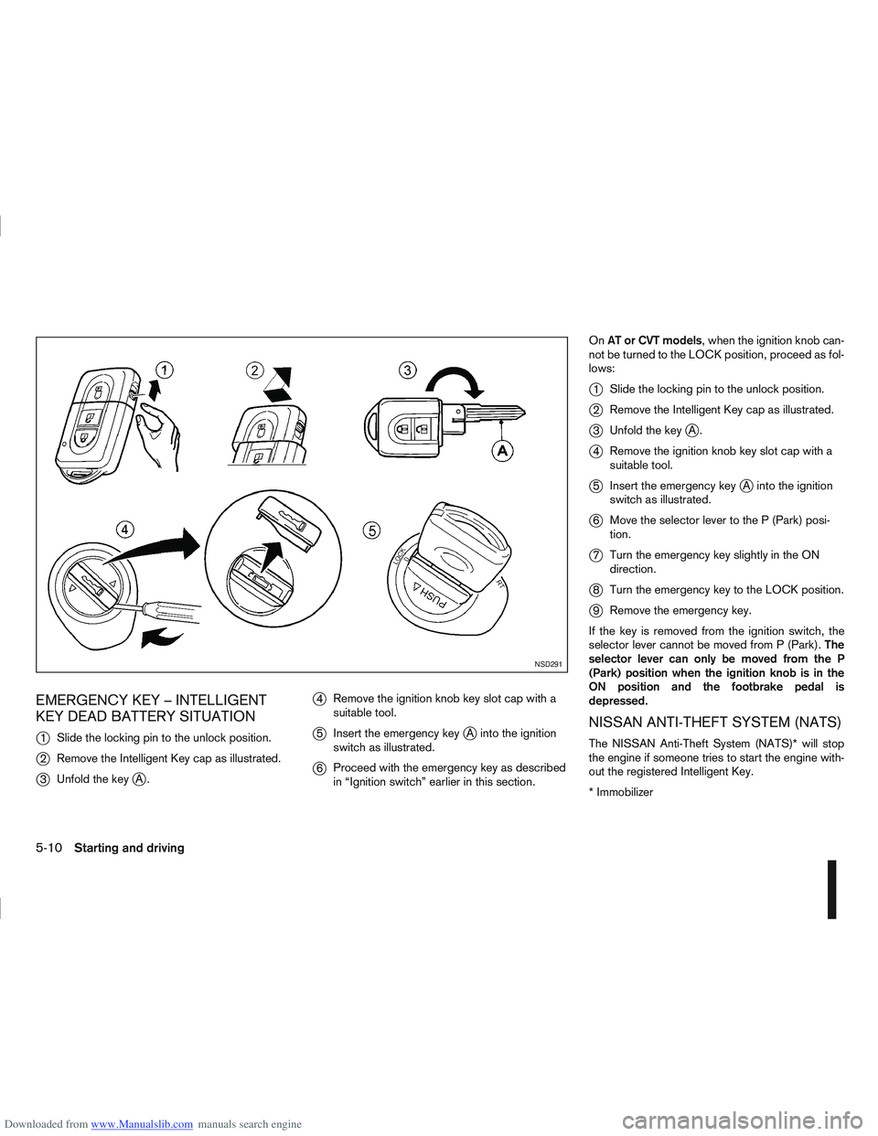
Downloaded from www.Manualslib.com manuals search engine EMERGENCY KEY – INTELLIGENT
KEY DEAD BATTERY SITUATION
j
1Slide the locking pin to the unlock position.
j2Remove the Intelligent Key cap as illustrated.
j3Unfold the keyjA.
j4Remove the ignition knob key slot cap with a
suitable tool.
j5Insert the emergency keyjA into the ignition
switch as illustrated.
j6 Proceed with the emergency key as described
in “Ignition switch” earlier in this section. On
AT or CVT models, when the ignition knob can-
not be turned to the LOCK position, proceed as fol-
lows:
j1 Slide the locking pin to the unlock position.
j2Remove the Intelligent Key cap as illustrated.
j3Unfold the keyjA.
j4Remove the ignition knob key slot cap with a
suitable tool.
j5Insert the emergency keyjA into the ignition
switch as illustrated.
j6 Move the selector lever to the P (Park) posi-
tion.
j7Turn the emergency key slightly in the ON
direction.
j8Turn the emergency key to the LOCK position.
j9Remove the emergency key.
If the key is removed from the ignition switch, the
selector lever cannot be moved from P (Park). The
selector lever can only be moved from the P
(Park) position when the ignition knob is in the
ON position and the footbrake pedal is
depressed.
NISSAN ANTI-THEFT SYSTEM (NATS)
The NISSAN Anti-Theft System (NATS)* will stop
the engine if someone tries to start the engine with-
out the registered Intelligent Key.
* Immobilizer
NSD291
5-10Starting and driving
Page 175 of 297
Downloaded from www.Manualslib.com manuals search engine mately 1/3 to the floor) and hold it then crank
the engine. Release the ignition switch and
the accelerator pedal when the engine starts.
CAUTION
Do not operate the starter for more than 15
seconds at a time. If the engine does not start,
turn the ignition switch to the “OFF” position
and wait 10 seconds (Petrol engine models)
or 20 seconds (Diesel engine models) before
cranking again, otherwise the starter could be
damaged.
If it becomes necessary to start the engine
with a booster battery and jumper leads, the
instructions and cautions contained in the
“Jump-starting” in the “6. In case of
emergency” section should be carefully fol-
lowed.
7. Warm-up
Allow the engine to idle for at least 30 seconds
after starting. Drive at moderate speed for a short
distance first, especially in cold weather.
WARNING
Do not leave the vehicle unattended while the
engine is warming up.
DRIVING WITH MANUAL
TRANSMISSION
CAUTION
Do not rest your foot on the clutch pedal while
driving. This may cause clutch damage.
Stop your vehicle completely before shifting
into the R (Reverse) position.
When you are shifting from one gear to an-
other, be certain to depress the clutch pedal
all the way to the floor to avoid clashing or
chipping the gears.
Avoid abrupt starts and acceleration for your
safety.
When quick acceleration is required for some
reason, shift to a lower gear and accelerate
until the vehicle reaches the maximum speed
in each gear. Do not exceed the speed limit of
any gear. Pay special attention when acceler-
ating or when shifting into a lower gear on
slippery surfaces. Sudden acceleration or
down shifting could cause the wheels to skid
and result in loss of control.
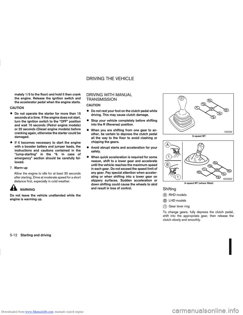
Shifting
j
A RHD models
jB LHD models
j1Gear lever ring
To change gears, fully depress the clutch pedal,
shift into the appropriate gear, then release the
clutch slowly and smoothly.
NSD340
5–speed MT
NSD292Z
6–speed MT (where fitted)
DRIVING THE VEHICLE
5-12Starting and driving
Page 179 of 297

Downloaded from www.Manualslib.com manuals search engine Manual shift mode
When the selector lever is shifted from D (Drive) to
the manual shift gate with the vehicle stopped or
while driving, the transmission enters manual shift
mode. Shift range can be selected manually.
In manual shift mode, the selected gear is displayed
on the position indicator in the combination meter.
Shift ranges up or down one by one as follows:
1st⇔2nd ⇔3rd ⇔4th ⇔5th ⇔6th
When shifting up, move the selector lever to the
+ (up) side. (Shifts to higher range).
When shifting down, move the selector lever to
the – (down) side. (Shifts to lower range).
Moving the selector lever rapidly to the same
side twice will shift the ranges in succession.
Use the 1st position when driving slowly on steep
hills, slow driving through deep snow, sand or
mud, or for maximum engine braking on steep
downhill grades.
Use the 2nd, 3rd or 4th position when driving
steep hills or for engine braking on steep down-
hill grades.
Use the 5th position for driving up or down long
slopes.
Use the 6th position for all normal forward driv-
ing. However, you need to shift down the gears
when accelerating or passing another vehicle.
When cancelling manual shift mode, return the
selector lever to the D (Drive) position. The trans-
mission returns to the normal driving mode.
In manual shift mode, the transmission may
not shift to the selected gear under certain
circumstances. This helps maintain driving
performance and reduces the chance of ve-
hicle damage or loss of control.
If the engine is revving up to a hazardous
speed in manual shift mode, the transmission
may shift up automatically. When the vehicle
speed decreases, the transmission automati-
cally shifts down and shifts to 1st gear before
the vehicle comes to a stop.
Accelerator downshift – In the D (Drive)
position
For rapid passing or driving uphill, fully depress the
accelerator pedal to the floor. This shifts the trans-
mission down into a lower gear, depending on the
vehicle speed.
Shift lock release
If the battery is discharged, the selector lever can-
not be moved from the P (Park) position even with
the brake pedal depressed and the ignition switch in
the ON position.
To move the selector lever, remove the cap
j1
(where fitted) then push the shift lock release button
jA with a suitable toolj2 (as illustrated) and press
the selector lever buttonj3 . It is now possible to
move the selector lever to the N (Neutral) position
j4.
For your safety, make sure the handbrake is applied
and the brake pedal is depressed during the opera-
tion.
If there is any problem moving the lever out of the P
(Park) position, have a NISSAN dealer or qualified
workshop to check the automatic transmission sys-
tem as soon as possible.
NSD347
Cap (where fitted)
5-16Starting and driving
Page 183 of 297
Downloaded from www.Manualslib.com manuals search engine Shift lock release
j
1LHD models
j2RHD models
jA Shift lock release button
If the battery charge is low or discharged, the selec-
tor lever may not move from the P (Park) position
even with the brake pedal depressed and the selec-
tor lever button pushed.
To move the selector lever, perform the following
procedure:
1. Models with Intelligent Key system:
Place the ignition switch in the “OFF” or LOCK
position.
Models without Intelligent Key system:
Place the ignition switch in the LOCK position,
and remove the key if it is inserted.
2. Apply the handbrake.
3. Push down the shift lock release button
jA.Use
a suitable tool.
4. Push and hold the selector lever button and move the selector lever to the N (Neutral) position while
holding down the shift lock release button.
Place the ignition switch in the ON position to un-
lock the steering wheel. The vehicle may be moved
to the desired location. For models with Intelligent Key system: If the battery
is discharged completely, the steering wheel cannot
be unlocked. Do not move the vehicle with the steer-
ing wheel locked.
If the selector lever cannot be moved out of the P
(Park) position, have a NISSAN dealer or qualified
workshop check the CVT system as soon as pos-
sible.
WARNING
If the selector lever cannot be moved from the P
(Park) position while the engine is running and
the brake pedal is depressed, the stop lights may
not work. Malfunctioning stop lights could cause
an accident injuring yourself and others.
High fluid temperature protection mode
This transmission has a high fluid temperature pro-
tection mode. If the fluid temperature becomes too
high (for example, when climbing steep grades in
high temperature with heavy loads, such as when
towing a trailer), engine power and, under some
conditions, vehicle speed will be decreased auto-
matically to reduce the chance of transmission dam-
age. Vehicle speed can be controlled with the ac-
celerator pedal, but engine and vehicle speed may
be limited.
Fail-safe
When the fail-safe operation occurs, the CVT will
not be shifted to the selected driving position.
If the vehicle is driven under extreme conditions,
such as excessive wheel spinning and subse- quent hard braking, the fail-safe system may be
activated. This will occur even if all electrical cir-
cuits are functioning properly. In this case, place
the ignition switch in the “OFF” position and wait
for 10 seconds. Then turn the ignition switch back
to the ON position. The vehicle should return to
its normal operating condition. If it does not re-
turn to its normal operating condition, have a
NISSAN dealer or qualified workshop check the
transmission and repair it if necessary.
WARNING
When the fail-safe operation occurs, vehicle
speed may be gradually reduced. The reduced
speed may be lower than other traffic, which
could increase the chance of a collision. Be es-
pecially careful when driving. If necessary, pull to
the side of the road at a safe place and allow the
transmission to return to normal operation, or
have it repaired if necessary.
5-20Starting and driving
Page 184 of 297
Downloaded from www.Manualslib.com manuals search engine NISSAN GREEN PROGRAM
The Stop/Start System is designed to prevent un-
necessary fuel consumption, exhaust emissions,
and noise during a journey:
When the vehicle comes to rest the engine is
automatically stopped*.
The engine is then automatically restarted before
you are ready to drive away**.
CAUTION
At the end of the journey the engine must be
stopped and ignition turned OFF. Lock the ve-
hicle as normal. Turning the ignition OFF will shut
down all electrical systems. Failure to do this may
result in a flat battery.
NORMAL OPERATION
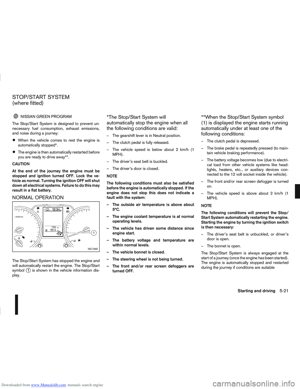
The Stop/Start System has stopped the engine and
will automatically restart the engine. The Stop/Start
symbol
j1 is shown in the vehicle information dis-
play.
*The Stop/Start System will
automatically stop the engine when all
the following conditions are valid:
– The gearshift lever is in Neutral position.
– The clutch pedal is fully released.
– The vehicle speed is below about 2 km/h (1 MPH).
– The driver’s seat belt is buckled.
– The driver’s door is closed.
NOTE
The following conditions must also be satisfied
before the engine is automatically stopped. If the
engine does not stop this does not indicate a
fault with the system:
– The outside air temperature is above about 5ºC.
– The engine coolant temperature is at normal operating levels.
– The vehicle has driven some distance since engine start.
– The battery voltage and temperature are within normal levels.
– The vehicle bonnet is closed.
– The steering wheel is not being turned.
– The front and/or rear screen defoggers are turned OFF.
**When the Stop/Start System symbol
(1) is displayed the engine starts running
automatically under at least one of the
following conditions:
– The clutch pedal is depressed.
– The brake pedal is repeatedly pressed (to main-tain vehicle braking performance).
– The battery voltage becomes low (due to electri- cal load from other vehicle systems like head-
lights, heaters, etc., or auxiliary devices con-
nected to the 12 volt socket inside the vehicle).
– The front and/or rear screen defogger is turned on.
– The vehicle speed is above about 2 km/h (1 MPH).
NOTE
The following conditions will prevent the Stop/
Start System automatically restarting the engine.
Starting the engine by turning the ignition switch
is then necessary:
– The driver’s seat belt is unbuckled, or driver’s door is open.
– The bonnet is open.
The Stop/Start System is always engaged at the
start of a journey (once the engine has been started).
The engine is automatically stopped and restarted
during the journey if conditions are suitable
NIC1640
STOP/START SYSTEM
(where fitted)
Starting and driving5-21