2010 NISSAN MURANO ignition
[x] Cancel search: ignitionPage 306 of 425
Black plate (302,1)
Model "Z51-D" EDITED: 2009/ 8/ 3
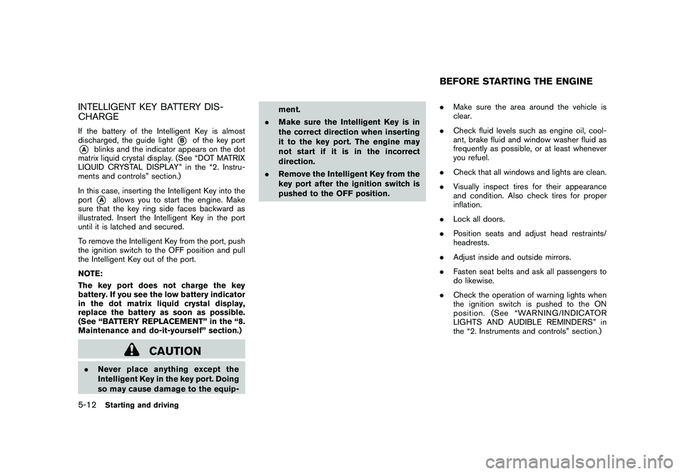
INTELLIGENT KEY BATTERY DIS-
CHARGEIf the battery of the Intelligent Key is almost
discharged, the guide light
*B
of the key port
*A
blinks and the indicator appears on the dot
matrix liquid crystal display. (See “DOT MATRIX
LIQUID CRYSTAL DISPLAY” in the “2. Instru-
ments and controls” section.)
In this case, inserting the Intelligent Key into the
port*A
allows you to start the engine. Make
sure that the key ring side faces backward as
illustrated. Insert the Intelligent Key in the port
until it is latched and secured.
To remove the Intelligent Key from the port, push
the ignition switch to the OFF position and pull
the Intelligent Key out of the port.
NOTE:
The key port does not charge the key
battery. If you see the low battery indicator
in the dot matrix liquid crystal display,
replace the battery as soon as possible.
(See “BATTERY REPLACEMENT” in the “8.
Maintenance and do-it-yourself” section.)
CAUTION
. Never place anything except the
Intelligent Key in the key port. Doing
so may cause damage to the equip- ment.
. Make sure the Intelligent Key is in
the correct direction when inserting
it to the key port. The engine may
not start if it is in the incorrect
direction.
. Remove the Intelligent Key from the
key port after the ignition switch is
pushed to the OFF position. .
Make sure the area around the vehicle is
clear.
. Check fluid levels such as engine oil, cool-
ant, brake fluid and window washer fluid as
frequently as possible, or at least whenever
you refuel.
. Check that all windows and lights are clean.
. Visually inspect tires for their appearance
and condition. Also check tires for proper
inflation.
. Lock all doors.
. Position seats and adjust head restraints/
headrests.
. Adjust inside and outside mirrors.
. Fasten seat belts and ask all passengers to
do likewise.
. Check the operation of warning lights when
the ignition switch is pushed to the ON
position. (See “WARNING/INDICATOR
LIGHTS AND AUDIBLE REMINDERS” in
the “2. Instruments and controls” section.)
BEFORE STARTING THE ENGINE
5-12
Starting and driving
Page 307 of 425
Black plate (303,1)
Model "Z51-D" EDITED: 2009/ 8/ 3
1. Apply the parking brake.
2. Move the selector lever to the P (Park) or N(Neutral) position. (P is recommended.)
The starter is designed not to operate unless
the selector lever is in either of the above
positions.
3. Push the ignition switch to the ON position. Depress the brake pedal and push the
ignition switch to start the engine.
To start the engine immediately, push and
release the ignition switch while depressing
the brake pedal with the ignition switch in
any position.
.If the engine is very hard to start in
extremely cold weather or when restart-
ing, depress the accelerator pedal a little
(approximately 1/3 to the floor) and
while holding, crank the engine. Release
the accelerator pedal when the engine
starts.
. If the engine is very hard to start
because it is flooded, depress the
accelerator pedal all the way to the floor
and hold it. Push the ignition switch to
the ON position to start cranking the
engine. After 5 or 6 seconds, stop
cranking by pushing the ignition switch
to OFF. After cranking the engine,
release the accelerator pedal. Crank the engine
with your foot off the
accelerator pedal by depressing the
brake pedal and pushing the push-
button ignition switch to start the engine.
If the engine starts, but fails to run,
repeat the above procedure.
CAUTION
Do not operate the starter for more
than 15 seconds at a time. If the engine
does not start, push the ignition switch
to OFF and wait 10 seconds before
cranking again, otherwise the starter
could be damaged.
4. Warm-up
Allow the engine to idle for at least 30
seconds after starting. Do not race the
engine while warming it up. Drive at
moderate speed for a short distance first,
especially in cold weather. In cold weather,
keep the engine running for a minimum of 2 -
3 minutes before shutting it off. Starting and
stopping the engine over a short period of
time may make the vehicle more difficult to
start.
5. To stop the engine, shift the selector lever to the P (Park) position and push the ignition
switch to the OFF position.
CONTINUOUSLY VARIABLE TRANS-
MISSION (CVT)The Continuously Variable Transmission (CVT)
in your vehicle is electronically controlled to
produce maximum power and smooth operation.
The recommended operating procedures for this
transmission are shown on the following pages.
Follow these procedures for maximum vehicle
performance and driving enjoyment.
Engine power may be automatically re-
duced to protect the CVT if the engine
speed increases quickly when driving on
slippery roads or while being tested on
some dynamometers.Starting the vehicle1. After starting the engine, fully depress thefoot brake pedal before moving the selector
lever out of the P (Park) position.
This CVT is designed so that the foot
brake pedal must be depressed before
shifting from P (Park) to any driving
position while the ignition switch is in
the ON position.
The selector lever cannot be moved out
of the P (Park) position and into any of
the other positions if the ignition
switch is pushed to the LOCK, OFF or
ACC position.
STARTING THE ENGINE DRIVING THE VEHICLE
Starting and driving
5-13
Page 310 of 425

Black plate (306,1)
Model "Z51-D" EDITED: 2009/ 8/ 3
Accelerator downshift
— In D position —For passing or hill climbing, fully depress the
accelerator pedal to the floor. This shifts the
transmission down into a lower gear, depending
on the vehicle speed.High fluid temperature protection modeThis transmission has a high fluid temperature
protection mode. If the fluid temperature be-
comes too high (for example, when climbing
steep grades in high temperature with heavy
loads, such as when towing a trailer) , engine
power and, under some conditions, vehicle
speed will be decreased automatically to reduce
the chance of transmission damage. Vehicle
speed can be controlled with the accelerator
pedal, but the engine and vehicle speed may be
limited.Fail-safeIf the vehicle is driven under extreme
conditions, such as excessive wheel spin-
ning and subsequent hard braking, the
fail-safe system may be activated. The MIL
may illuminate to indicate the fail-safe
mode is activated. (See “Malfunction In-
dicator Light (MIL)” in the “2. Instruments
and controls” section.) This will occur even
if all electrical circuits are functioning
properly. In this case, turn the ignition
switch to the OFF position and wait for 10seconds. Then turn the ignition switch
back to the ON position. The vehicle
should return to its normal operating
condition. If it does not return to its normal
operating condition, have a NISSAN dealer
check the transmission and repair if ne-
cessary.
WARNING
When the high fluid temperature pro-
tection mode or fail-safe operation
occurs, vehicle speed may be gradually
reduced. The reduced speed may be
lower than other traffic, which could
increase the chance of a collision. Be
especially careful when driving. If ne-
cessary, pull to the side of the road at a
safe place and allow the transmission
to return to normal operation, or have it
repaired if necessary.
SSD0693
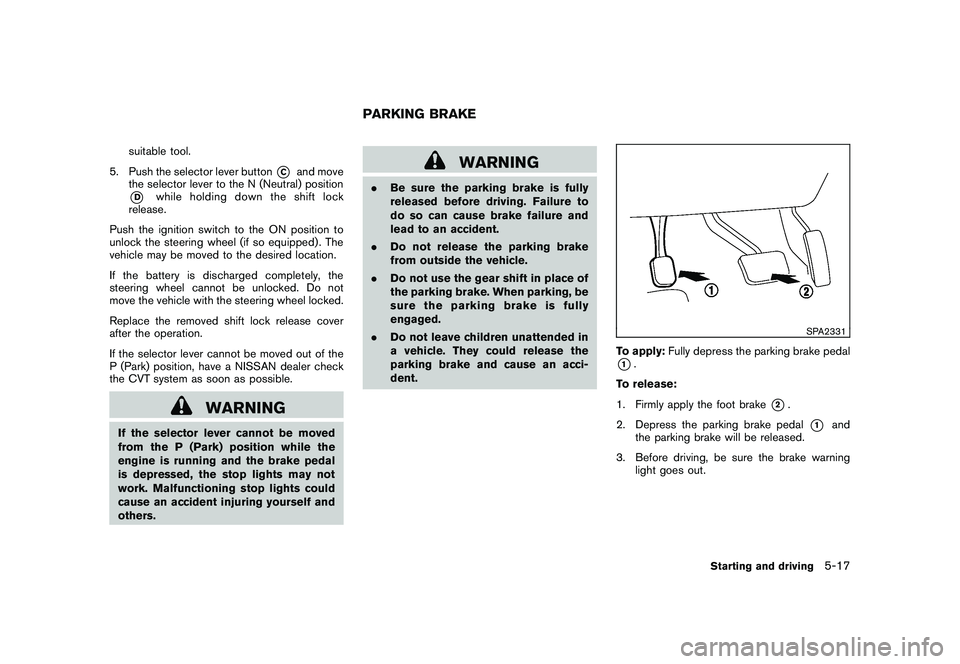
Shift lock releaseIf the battery charge is low or discharged, the
selector lever may not be moved from the P
(Park) position even with the brake pedal
depressed and the selector lever button pushed.
To move the selector lever, perform the following
procedure:
1. Push the ignition switch to the OFF or LOCK
position.
2. Apply the parking brake.
3. Remove the shift lock release cover
*A
using a suitable tool.
4. Push down the shift lock release
*B
using a
5-16
Starting and driving
Page 311 of 425
Black plate (307,1)
Model "Z51-D" EDITED: 2009/ 8/ 3
suitable tool.
5. Push the selector lever button
*C
and move
the selector lever to the N (Neutral) position
*D
while holding down the shift lock
release.
Push the ignition switch to the ON position to
unlock the steering wheel (if so equipped) . The
vehicle may be moved to the desired location.
If the battery is discharged completely, the
steering wheel cannot be unlocked. Do not
move the vehicle with the steering wheel locked.
Replace the removed shift lock release cover
after the operation.
If the selector lever cannot be moved out of the
P (Park) position, have a NISSAN dealer check
the CVT system as soon as possible.
WARNING
If the selector lever cannot be moved
from the P (Park) position while the
engine is running and the brake pedal
is depressed, the stop lights may not
work. Malfunctioning stop lights could
cause an accident injuring yourself and
others.
WARNING
. Be sure the parking brake is fully
released before driving. Failure to
do so can cause brake failure and
lead to an accident.
. Do not release the parking brake
from outside the vehicle.
. Do not use the gear shift in place of
the parking brake. When parking, be
sure the parking brake is fully
engaged.
. Do not leave children unattended in
a vehicle. They could release the
parking brake and cause an acci-
dent.
SPA2331
To apply: Fully depress the parking brake pedal*1.
To release:
1. Firmly apply the foot brake
*2.
2. Depress the parking brake pedal
*1
and
the parking brake will be released.
3. Before driving, be sure the brake warning light goes out.
PARKING BRAKE
Starting and driving
5-17
Page 316 of 425
Black plate (312,1)
Model "Z51-D" EDITED: 2009/ 8/ 3
*2: LOCK mode will change to AUTO modeautomatically when the vehicle has been
driven at a high speed. The AWD LOCK
indicator light turns off.
*3: LOCK mode will automatically be cancelled when the ignition switch is turned to the OFF
position.
. If the AWD LOCK switch is operated while
accelerating or decelerating, or if the ignition
switch is turned off, you may feel a jolt. This
is normal.
. The oil temperature of power train parts will
increase if the vehicle is continuously
operated under conditions where the differ-
ence in rotation between the front and rear
wheels is large (wheel slip) , such as when
driving the vehicle on rough roads through
sand, mud or freeing a stuck vehicle. In
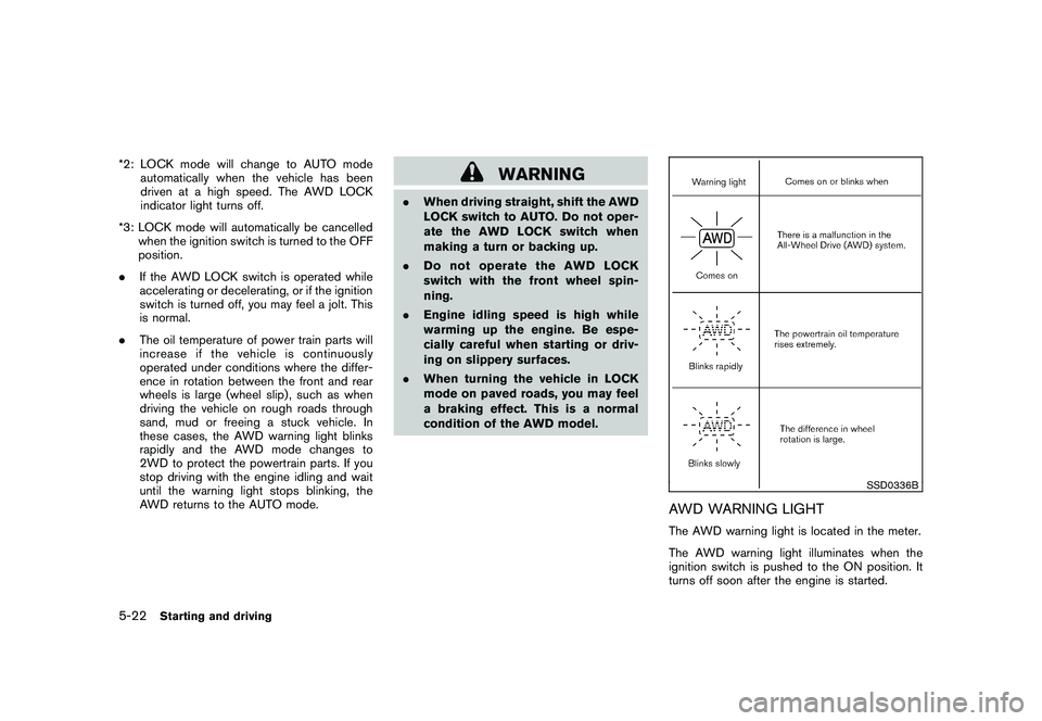
these cases, the AWD warning light blinks
rapidly and the AWD mode changes to
2WD to protect the powertrain parts. If you
stop driving with the engine idling and wait
until the warning light stops blinking, the
AWD returns to the AUTO mode.
WARNING
.When driving straight, shift the AWD
LOCK switch to AUTO. Do not oper-
ate the AWD LOCK switch when
making a turn or backing up.
. Do not operate the AWD LOCK
switch with the front wheel spin-
ning.
. Engine idling speed is high while
warming up the engine. Be espe-
cially careful when starting or driv-
ing on slippery surfaces.
. When turning the vehicle in LOCK
mode on paved roads, you may feel
a braking effect. This is a normal
condition of the AWD model.
SSD0336B
AWD WARNING LIGHTThe AWD warning light is located in the meter.
The AWD warning light illuminates when the
ignition switch is pushed to the ON position. It
turns off soon after the engine is started.
5-22
Starting and driving
Page 318 of 425
Black plate (314,1)
Model "Z51-D" EDITED: 2009/ 8/ 3
SSD0488
WARNING
.Do not stop or park the vehicle over
flammable materials such as dry
grass, waste paper or rags. They
may ignite and cause a fire.
. Safe parking procedures require
that both the parking brake be set
and the transmission placed into P
(Park) . Failure to do so could cause
the vehicle to move unexpectedly or
roll away and result in an accident.
Make sure the selector lever has
been pushed as far forward as it can go and cannot be moved without
depressing the foot brake pedal.
. Never leave the engine running
while the vehicle is unattended.
. Do not leave children unattended
inside the vehicle. They could un-
knowingly activate switches or con-
trols. Unattended children could
become involved in serious acci-
dents.
1. Firmly apply the parking brake.
2. Move the selector lever to the P (Park) position. 3. To help prevent the vehicle from rolling into
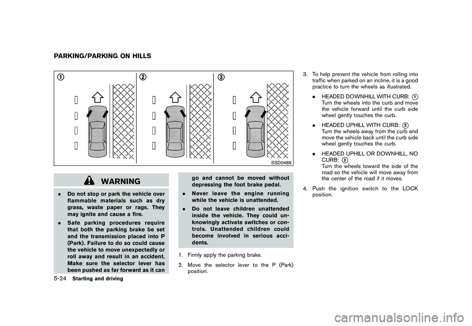
traffic when parked on an incline, it is a good
practice to turn the wheels as illustrated.
.HEADED DOWNHILL WITH CURB:
*1
Turn the wheels into the curb and move
the vehicle forward until the curb side
wheel gently touches the curb.
. HEADED UPHILL WITH CURB:
*2
Turn the wheels away from the curb and
move the vehicle back until the curb side
wheel gently touches the curb.
. HEADED UPHILL OR DOWNHILL, NO
CURB:
*3
Turn the wheels toward the side of the
road so the vehicle will move away from
the center of the road if it moves.
4. PushtheignitionswitchtotheLOCK position.
PARKING/PARKING ON HILLS5-24
Starting and driving
Page 322 of 425
Black plate (318,1)
Model "Z51-D" EDITED: 2009/ 8/ 3
The VDC OFF switch is used to turn off the VDC
system. The VDC off indicator illuminates to
indicate the VDC system is off. When the VDC
switch is used to turn off the system, the VDC
system still operates to prevent one drive wheel
from slipping by transferring power to a non
slipping drive wheel. The
indicator flashes
if this occurs. All other VDC functions are off and
the Slip indicator will not flash. The VDC System
is automatically reset to on when the ignition
switch is placed in the off position then back to
the on position.
The VDC system computer has a built-in
diagnostic feature that tests the system each
time you start the engine and move the vehicle at
a low speed forward or backward. When the
self-test occurs, you may hear a “clunk” noise
and/or feel a pulsation in the brake pedal. This is
normal and is not an indication of a malfunction.
WARNING
. The VDC system is designed to help
improve driving stability but does
not prevent accidents due to abrupt
steering operation at high speeds or
due to careless or dangerous driv-
ing techniques. Reduce vehicle
speed and be especially careful
when driving and cornering on slip-
pery surfaces and always drive care- fully.
. If engine control related parts are
not standard equipment or are ex-
tremely deteriorated, both the
and
indicator lights may illumi-
nate.
. Do not modify the vehicle’s suspen-
sion. If suspension parts such as
shock absorbers, struts, springs,
stabilizer bars, bushings and
wheels are not NISSAN approved
for your vehicle or are extremely
deteriorated the VDC system may
not operate properly. This could
adversely affect vehicle handling
performance, and the
indicator
may flash or bothand
indicator lights may illuminate.
. If brake related parts such as brake
pads, rotors and calipers are not
standard equipment or are extre-
mely deteriorated, the VDC system
may not operate properly and both
and
indicator lights may
illuminate.
. When driving on extremely inclined
surfaces such as higher banked
corners, the VDC system may not operate properly and the
in-
dicator may flash or bothand
indicator lights may illuminate.
Do not drive on these types of
roads.
. When driving on an unstable sur-
face such as a turntable, ferry,
elevator or ramp, the
indicator
may flash or bothand
indicator lights may illuminate. This
is not a malfunction. Restart the
engine after driving onto a stable
surface.
. If wheels or tires other than the
recommended ones are used, the
VDC system may not operate prop-
erly and the
indicator may flash
or bothand
indicator
lights may illuminate.
. The VDC system is not a substitute
for winter tires or tire chains on a
snow covered road.
. The ABLS system helps provide
increased traction, but will not pre-
vent accidents due to abrupt steer-
ing operation or by careless driving
or dangerous driving practices. Re-
duce vehicle speed and be espe-
5-28
Starting and driving
Page 336 of 425
Black plate (332,1)
Model "Z51-D" EDITED: 2009/ 8/ 3
unnecessary electrical systems (lights, hea-
ter, air conditioner, etc.) .
3. Remove vent caps on the battery (if so equipped) . Cover the battery with a firmly
wrung out moist cloth to reduce explosion
hazard.
4. Connect jumper cables in the sequence as illustrated (
*1
?
*2
?
*3
?
*4).
For models with a steering wheel lock
mechanism, if the battery is discon-
nected or discharged, the steering
wheel will lock and cannot be turned.
Supply power using jumper cables
before pushing the ignition switch and
disengaging the steering lock.
CAUTION
. Always connect positive (+) to posi-
tive (+) and negative ( �) to body
ground (for example, as illustrated) ,
not to the battery.
. Make sure the jumper cables do not
touch moving parts in the engine
compartment and that the cable
clamps do not contact any other
metal.
5. Start the engine of the booster vehicle
*B
and let it run for a few minutes.
6. Keep the engine speed of the booster vehicle
*B
at about 2,000 rpm, and start
the engine of the vehicle
*A
being jump
started.
CAUTION
Do not keep the starter motor engaged
for more than 10 seconds. If the engine
does not start right away, turn the
ignition switch to the OFF position
and wait 10 seconds before trying
again.
7. After starting your engine, carefully discon- nect the negative cable and then the positive
cable (
*4
?
*3
?
*2
?
*1).
8. Replace the vent caps (if so equipped) . Be sure to dispose of the cloth used to cover
the vent holes as it may be contaminated
with corrosive acid. Do not attempt to start the engine by pushing.
CAUTION
Continuously Variable Transmission
(CVT) models cannot be push-started
or tow-started. Attempting to do so may
cause transmission damage.PUSH STARTING
6-10
In case of emergency