Page 2656 of 3745
FRONT SUSPENSION ASSEMBLYFSU-9
< SERVICE INFORMATION >
C
DF
G H
I
J
K L
M A
B
FSU
N
O P
3. Put a mark on base line of the tread (rear side) of both tires at the same height of hub center. These are measuring points.
4. Measure distance (A) from rear side.
5. Push vehicle slowly ahead to rotate wheels 180 degrees (1/2 turn).
CAUTION:
If wheels have rotated more than 180 degrees (1/2 turn), try
the above procedure again from the beginning. Never push
vehicle backward.
6. Measure distance (B) from front side.
7. Use the formula below to calculate total toe-in.
• If the total toe-in is outside the specification, adjust toe-in by varying the length of between steeringouter socket and inner socket.
AFA050
SFA234AC
Total toe-in = A - B
For total toe-in specification, refer to FSU-17, "
Wheel Alignment (Unladen*)" .
Revision: January 20102010 Versa
Page 2671 of 3745

PRECAUTIONSGI-5
< SERVICE INFORMATION >
C
DE
F
G H
I
J
K L
M B
GI
N
O P
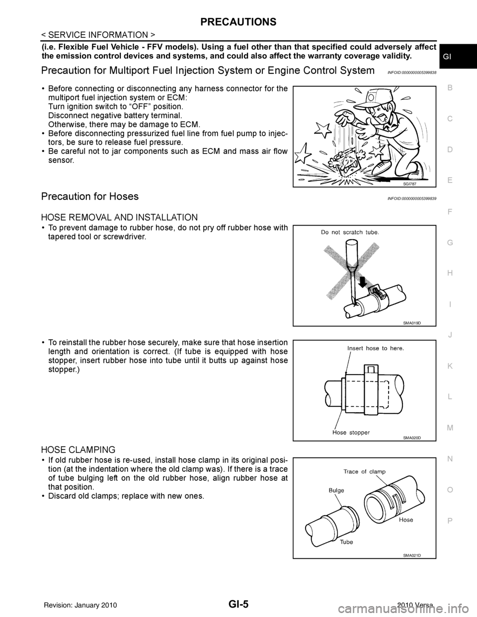
(i.e. Flexible Fuel Vehicle - FFV models). Using a fu el other than that specified could adversely affect
the emission control devices and systems, and could also affect the warranty coverage validity.
Precaution for Multiport Fuel Injection System or Engine Control SystemINFOID:0000000005399838
• Before connecting or disconnecting any harness connector for the
multiport fuel injection system or ECM:
Turn ignition switch to “OFF” position.
Disconnect negative battery terminal.
Otherwise, there may be damage to ECM.
• Before disconnecting pressurized fuel line from fuel pump to injec- tors, be sure to release fuel pressure.
• Be careful not to jar components such as ECM and mass air flow sensor.
Precaution for HosesINFOID:0000000005399839
HOSE REMOVAL AND INSTALLATION
• To prevent damage to rubber hose, do not pry off rubber hose withtapered tool or screwdriver.
• To reinstall the rubber hose securely, make sure that hose insertion length and orientation is correct. (If tube is equipped with hose
stopper, insert rubber hose into tube until it butts up against hose
stopper.)
HOSE CLAMPING
• If old rubber hose is re-used, install hose clamp in its original posi-tion (at the indentation where the old clamp was). If there is a trace
of tube bulging left on the old rubber hose, align rubber hose at
that position.
• Discard old clamps; replace with new ones.
SGI787
SMA019D
SMA020D
SMA021D
Revision: January 20102010 Versa
Page 2712 of 3745
GI-46
< SERVICE INFORMATION >
IDENTIFICATION INFORMATION
CVT NUMBER
DimensionsINFOID:0000000005399865
Unit: mm (in)
Wheels & TiresINFOID:0000000005399866
HR16DE
MR18DE
: Vehicle front
PCIB1612E
LAIA0074E
Overall lengthHatchback: 4,297 (169.2) Sedan: 4473 (176.1)
Overall width 1,695 (66.7)
Overall height 1,538 (60.5)
Front tread 1,480 (58.3)
Rear tread 1,485 (58.5)
Wheelbase 2,600 (102.4)
Road wheel St ee l
Size 14 x 5.0 JJ
Offset mm (in)40 (1.57)
Tire size
Conventional 185/65R14
Spare T125/70D15
Road wheel St ee l
Size 15 x 5.5 JJ
Offset mm (in)40 (1.57)
Road wheel Aluminum
Size 15 x 5.5 JJ
Offset mm (in)40 (1.57)
Road wheel Aluminum
Size 16 X 5.5 JJ
Offset mm (in)40 (1.57)
Revision: January 20102010 Versa
Page 3202 of 3745
![NISSAN LATIO 2010 Service Repair Manual MT-18
< SERVICE INFORMATION >[RS5F91R]
TRANSAXLE ASSEMBLY
CAUTION:
• Make sure the transaxle assembly does not interfer
e with the wire harnesses and clutch tube.
• When installing transaxle assem NISSAN LATIO 2010 Service Repair Manual MT-18
< SERVICE INFORMATION >[RS5F91R]
TRANSAXLE ASSEMBLY
CAUTION:
• Make sure the transaxle assembly does not interfer
e with the wire harnesses and clutch tube.
• When installing transaxle assem](/manual-img/5/57358/w960_57358-3201.png)
MT-18
< SERVICE INFORMATION >[RS5F91R]
TRANSAXLE ASSEMBLY
CAUTION:
• Make sure the transaxle assembly does not interfer
e with the wire harnesses and clutch tube.
• When installing transaxle assembly, do not bring input shaft into contact with clutch cover.
• If transaxle is removed from the vehicle, always replace CSC. Refer to CL-13, "
Removal and Installa-
tion".
• When installing the transaxle assembly to the engine, install the
bolts according to the following:
(A): Transaxle to engine
(B): Engine to transaxle
• After installation perform the following:
- Bleed the air from the clutch hydraulic system. Refer to CL-9, "
Air Bleeding Procedure".
- Check for oil leakage and oil level. Refer to MT-11, "
Inspection".
- Check the control linkage. Refer to MT-15, "
Inspection".
Disassembly and AssemblyINFOID:0000000005397178
COMPONENTS
Case and Housing Component
Bolt No.1234
Quantity 2213
Bolt length “ ”
mm (in) 55
(2.17) 49
(1.93) 69
(2.72) 55
(2.17)
Tightening torque
N·m (kg-m, ft-lb) 48.0
(4.9, 35)
PCIB1517E
Revision: January 20102010 Versa
Page 3246 of 3745
MT-62
< SERVICE INFORMATION >[RS6F94R]
TRANSAXLE ASSEMBLY
• When installing the transaxle assembly to the engine, install the
bolts as shown.
CAUTION:
When installing transaxle assembly, be careful not to bring
transaxle input shaft into co ntact with clutch cover.
A: M/T to engine
B: Engine to M/T
• Bleed the air from the clutch hydraulic system. Refer to CL-9, "
Air Bleeding Procedure".
• After installation, check oil level, and check for leaks and loose mechanisms. Refer to MT-54, "
Checking M/T
Oil".
Disassembly and AssemblyINFOID:0000000005716043
COMPONENTS
Case and Housing Components
Bolt No.12
Quantity 36
Bolt length “ ” mm (in) 60 (2.36)
50 (1.97)
Tightening torque
N·m (kg-m, ft-lb) 62.0 (6.3, 46)
PCIB1786E
Revision: January 20102010 Versa
Page 3468 of 3745

PS-10
< SERVICE INFORMATION >
STEERING COLUMN
6. Remove steering column assembly mounting nuts, and then remove steering column assembly from vehi-cle.
7. Remove bolt of intermediate shaft (lower side), and then remove intermediate shaft from vehicle.
8. Remove screws of bracket and EPS control unit, and then remove bracket and EPS control unit from steering column assembly.
INSPECTION AFTER REMOVAL
• Check each part of steering column assembly, EPS control unit and intermediate shaft for damage and.replace as necessary.
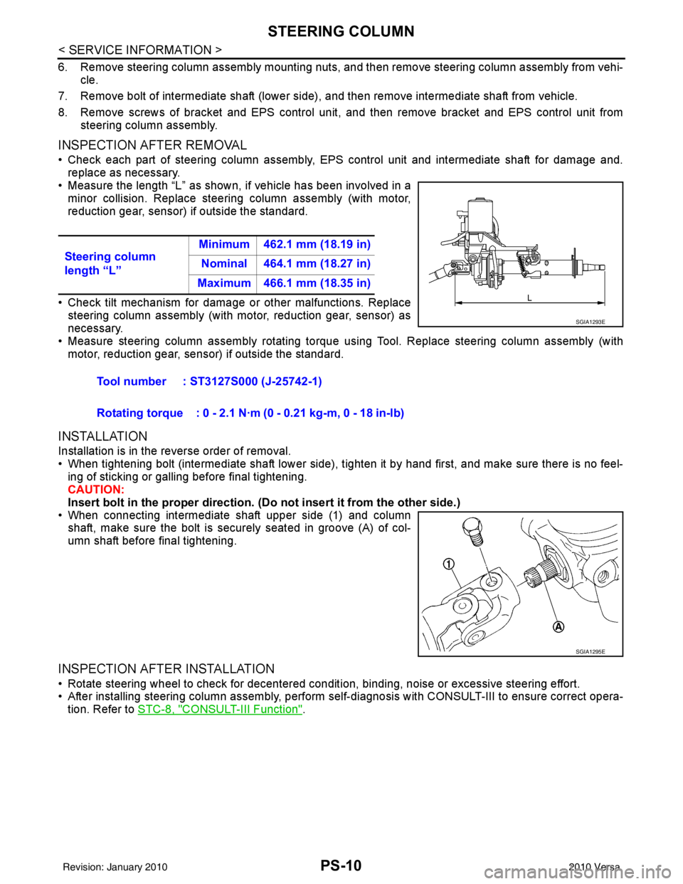
• Measure the length “L” as shown, if vehicle has been involved in a minor collision. Replace steering column assembly (with motor,
reduction gear, sensor) if outside the standard.
• Check tilt mechanism for damage or other malfunctions. Replace
steering column assembly (with motor, reduction gear, sensor) as
necessary.
• Measure steering column assembly rotating torque using Tool. Replace steering column assembly (with motor, reduction gear, sensor) if outside the standard.
INSTALLATION
Installation is in the reverse order of removal.
• When tightening bolt (intermediate shaft lower side), tighten it by hand first, and make sure there is no feel-
ing of sticking or galling before final tightening.
CAUTION:
Insert bolt in the proper direction. (Do not insert it from the other side.)
• When connecting intermediate shaft upper side (1) and column shaft, make sure the bolt is securely seated in groove (A) of col-
umn shaft before final tightening.
INSPECTION AFTER INSTALLATION
• Rotate steering wheel to check for decentered conditi on, binding, noise or excessive steering effort.
• After installing steering column assembly, perform self-diagnosis with CONSULT-III to ensure correct opera-
tion. Refer to STC-8, "
CONSULT-III Function".
Steering column
length “L”
Minimum 462.1 mm (18.19 in)
Nominal 464.1 mm (18.27 in)
Maximum 466.1 mm (18.35 in)
Tool number : ST3127S000 (J-25742-1)
Rotating torque : 0 - 2.1 N·m (0 - 0.21 kg-m, 0 - 18 in-lb)
SGIA1293E
SGIA1295E
Revision: January 20102010 Versa
Page 3474 of 3745
PS-16
< SERVICE INFORMATION >
POWER STEERING GEAR
13. Install boot clamp (1) to boot using Tool.NOTE:
Install large diameter side boot clamp (1) securely to boot
groove, and crimp it so as to have clearance of 3 mm (0.12 in) or
less as shown.
14. Install joint cover (1) to gear housing assembly (2). CAUTION:
Install joint cover so that the protrusion for locating is
securely set to gear housing groove.
15. Adjust inner socket to standard length “L”, and then tighten lock nut to the specified torque. Check length of inner socket “L”
again after tightening lock nut. Make sure that the length is the
standard.
CAUTION:
Adjust toe-in. Refer to FSU-7, "
Wheel Alignment Inspec-
tion". Length achieved after toe-in adjustment is not neces-
sarily the above value. Tool number : KV40107300 ( — )
SGIA1302E
SGIA1303E
Inner socket length “L” : 57.8 mm (2.276 in)
SGIA0167E
Revision: January 20102010 Versa
Page 3475 of 3745

SERVICE DATA AND SPECIFICATIONS (SDS)PS-17
< SERVICE INFORMATION >
C
DE
F
H I
J
K L
M A
B
PS
N
O P
SERVICE DATA AND SPECIFICATIONS (SDS)
Steering WheelINFOID:0000000005396939
Steering AngleINFOID:0000000005396940
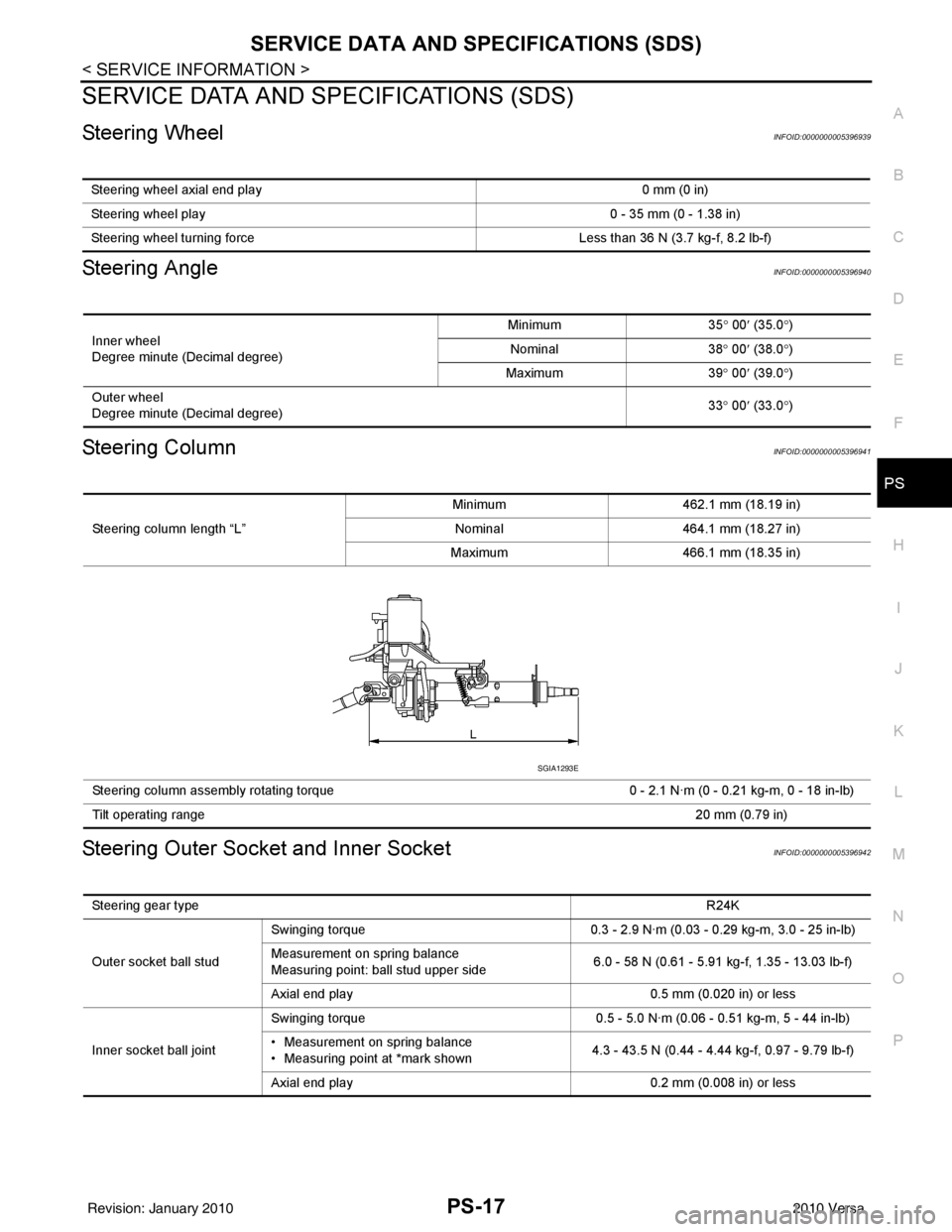
Steering ColumnINFOID:0000000005396941
Steering Outer Socket and Inner SocketINFOID:0000000005396942
Steering wheel axial end play 0 mm (0 in)
Steering wheel play 0 - 35 mm (0 - 1.38 in)
Steering wheel turning force Less than 36 N (3.7 kg-f, 8.2 lb-f)
Inner wheel
Degree minute (Decimal degree)Minimum
35° 00 ′ (35.0 °)
Nominal 38° 00 ′ (38.0 °)
Maximum 39° 00 ′ (39.0 °)
Outer wheel
Degree minute (Decimal degree) 33
° 00 ′ (33.0 °)
Steering column length “L” Minimum
462.1 mm (18.19 in)
Nominal 464.1 mm (18.27 in)
Maximum 466.1 mm (18.35 in)
Steering column assembly rotating torque 0 - 2.1 N·m (0 - 0.21 kg-m, 0 - 18 in-lb)
Tilt operating range 20 mm (0.79 in)
SGIA1293E
Steering gear type R24K
Outer socket ball stud Swinging torque
0.3 - 2.9 N·m (0.03 - 0.29 kg-m, 3.0 - 25 in-lb)
Measurement on spring balance
Measuring point: ball stud upper side 6.0 - 58 N (0.61 - 5.91 kg-f, 1.35 - 13.03 lb-f)
Axial end play 0.5 mm (0.020 in) or less
Inner socket ball joint Swinging torque
0.5 - 5.0 N·m (0.06 - 0.51 kg-m, 5 - 44 in-lb)
• Measurement on spring balance
• Measuring point at *mark shown 4.3 - 43.5 N (0.44 - 4.44 kg-f, 0.97 - 9.79 lb-f)
Axial end play 0.2 mm (0.008 in) or less
Revision: January 20102010 Versa