2010 NISSAN LATIO brake fluid
[x] Cancel search: brake fluidPage 883 of 3745

REAR DRUM BRAKEBR-35
< SERVICE INFORMATION >
C
DE
G H
I
J
K L
M A
B
BR
N
O P
REAR DRUM BRAKE
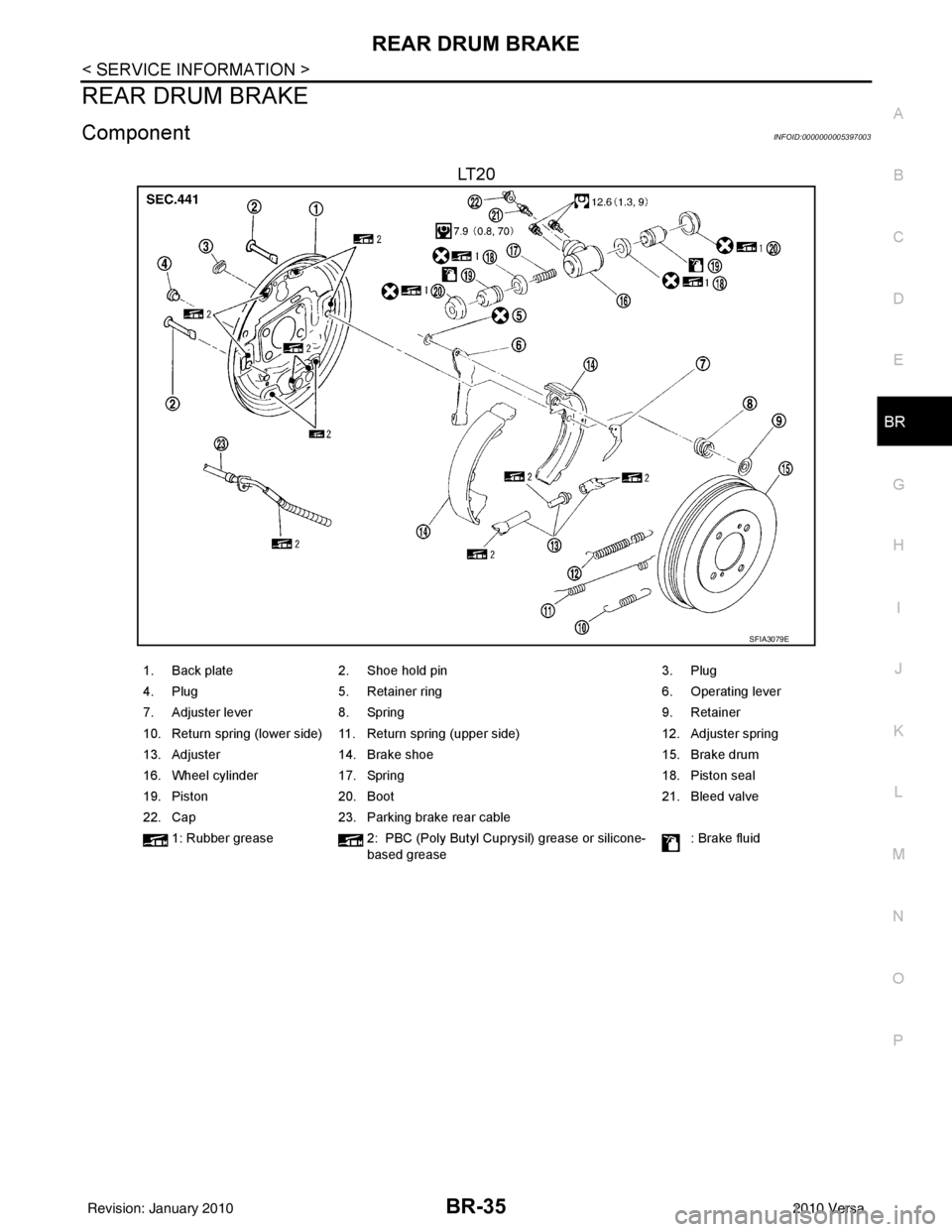
ComponentINFOID:0000000005397003
LT 2 0
SFIA3079E
1. Back plate 2. Shoe hold pin 3. Plug
4. Plug 5. Retainer ring 6. Operating lever
7. Adjuster lever 8. Spring 9. Retainer
10. Return spring (lower side) 11. Return spring (upper side) 12. Adjuster spring
13. Adjuster 14. Brake shoe 15. Brake drum
16. Wheel cylinder 17. Spring 18. Piston seal
19. Piston 20. Boot 21. Bleed valve
22. Cap 23. Parking brake rear cable
1: Rubber grease 2: PBC (Poly Butyl Cuprysil) grease or silicone-
based grease : Brake fluid
Revision: January 20102010 Versa
Page 884 of 3745

BR-36
< SERVICE INFORMATION >
REAR DRUM BRAKE
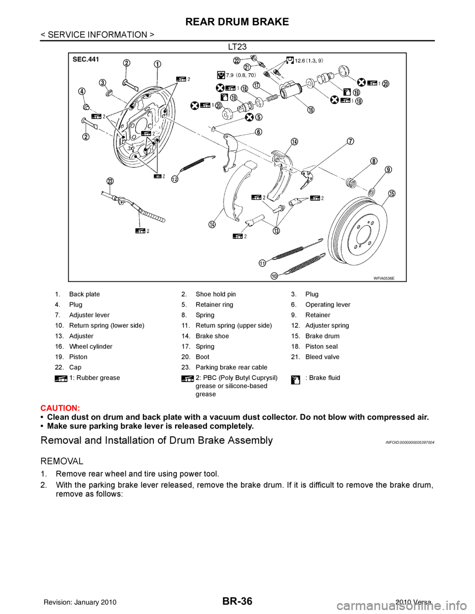
LT23
CAUTION:
• Clean dust on drum and back plate with a vacuum dust collector. Do not blow with compressed air.
• Make sure parking brake lever is released completely.
Removal and Installation of Drum Brake AssemblyINFOID:0000000005397004
REMOVAL
1. Remove rear wheel and tire using power tool.
2. With the parking brake lever released, remove the brak e drum. If it is difficult to remove the brake drum,
remove as follows:
WFIA0536E
1. Back plate 2. Shoe hold pin3. Plug
4. Plug 5. Retainer ring6. Operating lever
7. Adjuster lever 8. Spring9. Retainer
10. Return spring (lower side) 11. Return spring (upper side) 12. Adjuster spring
13. Adjuster 14. Brake shoe15. Brake drum
16. Wheel cylinder 17. Spring18. Piston seal
19. Piston 20. Boot21. Bleed valve
22. Cap 23. Parking brake rear cable
1: Rubber grease 2: PBC (Poly Butyl Cuprysil)
grease or silicone-based
grease : Brake fluid
Revision: January 20102010 Versa
Page 886 of 3745

BR-38
< SERVICE INFORMATION >
REAR DRUM BRAKE
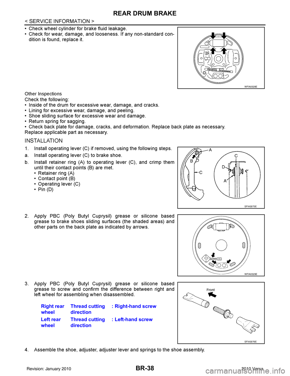
• Check wheel cylinder for brake fluid leakage.
• Check for wear, damage, and looseness. If any non-standard con-dition is found, replace it.
Other Inspections
Check the following:
• Inside of the drum for excessive wear, damage, and cracks.
• Lining for excessive wear, damage, and peeling.
• Shoe sliding surface for excessive wear and damage.
• Return spring for sagging.
• Check back plate for damage, cracks, and deformation. Replace back plate as necessary.
Replace applicable part as necessary.
INSTALLATION
1. Install operating lever (C) if removed, using the following steps.
a. Install operating lever (C) to brake shoe.
b. Install retainer ring (A) to operating lever (C), and crimp them
until their contact points (B) are met.
• Retainer ring (A)
• Contact point (B)
• Operating lever (C)
•Pin (D)
2. Apply PBC (Poly Butyl Cuprysil) grease or silicone based grease to brake shoes sliding surfaces (the shaded areas) and
other parts on the back plate as indicated by arrows.
3. Apply PBC (Poly Butyl Cuprysil) grease or silicone based grease to screw and confirm the difference between right and
left wheel for assembling when disassembled.
4. Assemble the shoe, adjuster, adjuster lever and springs to the shoe assembly.
WFIA0528E
SFIA3075E
WFIA0529E
Right rear
wheel Thread cutting
direction : Right-hand screw
Left rear
wheel Thread cutting
direction : Left-hand screw
SFIA3076E
Revision: January 20102010 Versa
Page 887 of 3745

REAR DRUM BRAKEBR-39
< SERVICE INFORMATION >
C
DE
G H
I
J
K L
M A
B
BR
N
O P
5. Connect the parking brake rear cable to the operating lever.
6. Install the shoe assembly. After assembly, be sure that each part is installed properly. CAUTION:
Do not damage the wheel cylinder piston boot.
7. Install the brake drum.
8. Depress brake pedal for several times (approximately 2 or 3 times).
9. Adjust clearance of brake shoe. Refer to PB-5, "
On-Vehicle Service".
10. Install rear wheel and tire. Refer to WT-7, "
Adjustment".
Removal and Installati on of Wheel CylinderINFOID:0000000005397005
REMOVAL
1. Drain the brake fluid. Refer to BR-9, "Drain and Refill".
2. Remove the rear brake shoe assembly. Refer to BR-36, "
Removal and Installation of Drum Brake Assem-
bly".
3. Remove the bleed valve.
4. Disconnect the brake tube from the wheel cylinder.
5. Remove the wheel cylinder bolts and then remove the wheel cylinder from the back plate.
INSTALLATION
Installation is in the reverse order of removal.
• Tighten bolts and bleed valve to the specified torque. Refer to BR-35, "
Component".
• Refill with new brake fluid and bleed the air. Refer to BR-9, "
Bleeding Brake System".
Disassembly and Assembly of Wheel CylinderINFOID:0000000005397006
DISASSEMBLY
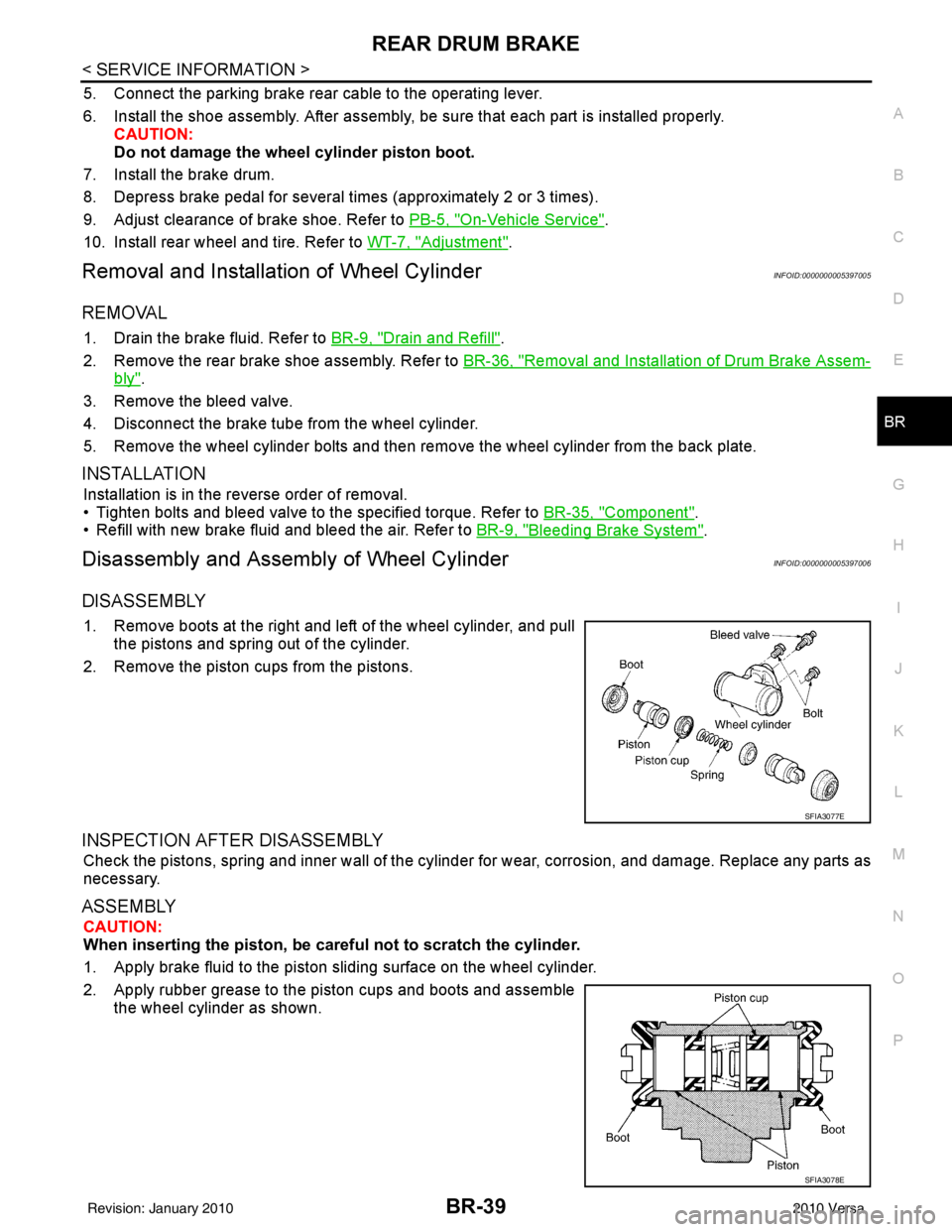
1. Remove boots at the right and left of the wheel cylinder, and pull
the pistons and spring out of the cylinder.
2. Remove the piston cups from the pistons.
INSPECTION AFTER DISASSEMBLY
Check the pistons, spring and inner wall of the cylinder for wear, corrosion, and damage. Replace any parts as
necessary.
ASSEMBLY
CAUTION:
When inserting the piston, be caref ul not to scratch the cylinder.
1. Apply brake fluid to the piston sliding surface on the wheel cylinder.
2. Apply rubber grease to the piston cups and boots and assemble the wheel cylinder as shown.
SFIA3077E
SFIA3078E
Revision: January 20102010 Versa
Page 888 of 3745

BR-40
< SERVICE INFORMATION >
SERVICE DATA AND SPECIFICATIONS (SDS)
SERVICE DATA AND SPECIFICATIONS (SDS)
General SpecificationINFOID:0000000005397007
HR16DE
MR18DE
TypeWith ABS only or VDC/TCS/ABSWithout ABS
Front brake Brake model AD22VK
Cylinder bore diameter 53.97 mm (2.125 in)
Pad
Length × width × thickness 115.0 mm ×
41.0 mm × 9.0 mm
(4.528 in × 1.614 in × 0.354 in)
Rotor outer diameter × thickness 260 mm × 22.0 mm (10.24 in × 0.866 in)
Rear brake Brake model LT20
Cylinder bore diameter 15.87 mm (0.625 in)17.46 mm (0.687 in)
Drum inner diameter 203 mm (7.992 in)
Master cylinder Cylinder bore diameter 22.22 mm (0.875 in)
Brake booster Booster model C255
Diaphragm diameter 255 mm (10.04 in)
Recommended brake fluid DOT 3
Front brake Brake modelCLZ25VF
Cylinder bore diameter 57.2 mm (2.252 in)
Pad
Length × width × thickness 125.6 mm
× 48.0 mm × 9.5 mm
(4.945 in × 1.890 in × 0.374 in)
Rotor outer diameter × thickness 280 mm × 24.0 mm (11.02 in × 0.945 in)
Rear brake Brake model LT23
Cylinder bore diameter 19.06 mm (0.750 in)
Drum inner diameter 228.6 mm (9.000 in)
Master cylinder Cylinder bore diameter 23.81 ± 0.015 mm (0.937 ± 0.001 in)
Brake booster Booster model C255
Diaphragm diameter 255 mm (10.04 in)
Recommended brake fluid DOT 3
Revision: January 20102010 Versa
Page 892 of 3745

BRC-2
SYSTEM DESCRIPTION ................................ ...43
System Component ............................................. ...43
ABS Function ....................................... ...................43
EBD Function ...................................................... ...43
TCS Function ..........................................................44
VDC Function .........................................................44
Wheel Sensors .......................................................44
Fail-Safe Function ..................................................44
Hydraulic Circuit Diagram .......................................45
CAN COMMUNICATION ...................................46
System Description .................................................46
TROUBLE DIAGNOSIS .....................................47
How to Perform Trouble Diagnosis for Quick and
Accurate Repair ................................................... ...
47
Component Parts and Harness Connector Loca-
tion ..........................................................................
50
Schematic ...............................................................51
Wiring Diagram - VDC - ..........................................52
Basic Inspection .....................................................56
Warning Lamp and Indicator Timing .......................57
Control Unit Input/Output Signal Standard .............57
CONSULT-III Function (ABS) .................................60
TROUBLE DIAGNOSIS FOR SELF-DIAG-
NOSTIC ITEMS ............................................... ...
67
Wheel Sensor System Inspection ...........................67
Engine System Inspection ................................... ...68
ABS/TCS/VDC Control Unit Inspection ..................68
Steering Angle Sensor System Inspection .......... ...69
Yaw Rate/Side/Decel G Sensor System Inspec-
tion ....................................................................... ...
70
Solenoid and VDC Change-Over Valve System
Inspection ...............................................................
72
Actuator Motor, Motor Relay, and Circuit Inspec-
tion ....................................................................... ...
73
Stop Lamp Switch System Inspection ....................74
ABS/TCS/VDC Control Unit Power and Ground
Systems Inspection .............................................. ...
75
Brake Fluid Level Switch System Inspection ..........76
Pressure Sensor System Inspection .......................77
Transmission Range Switch System Inspection .. ...78
CAN Communication System Inspection ................79
Component Inspection ............................................79
TROUBLE DIAGNOSES FOR SYMPTOMS .....81
ABS Works Frequently ............................................81
Unexpected Pedal Action ..................................... ...81
Long Stopping Distance ..........................................82
ABS Does Not Work ...............................................82
Pedal Vibration or ABS Op eration Noise ................82
ABS Warning Lamp Does Not Come On When Ig-
nition Switch Is Turned On ................................... ...
83
ABS Warning Lamp Stays On When Ignition
Switch Is Turned On ............................................ ...
83
Vehicle Jerks During TCS/VDC Activation ..............84
ON-VEHICLE SERVICE ....................................85
Adjustment of Steering Angle Sensor Neutral Po-
sition ..................................................................... ...
85
WHEEL SENSORS ............................................86
Removal and Installation .........................................86
SENSOR ROTOR ........................................... ...88
Removal and Installation .........................................88
ACTUATOR AND ELECTRIC UNIT (ASSEM-
BLY) ................................................................ ...
89
Removal and Installation .........................................89
STEERING ANGLE SENSOR ........................ ...91
Removal and Installation .........................................91
G SENSOR ........................................................92
Removal and Installation .........................................92
Revision: January 20102010 Versa
Page 894 of 3745
![NISSAN LATIO 2010 Service Repair Manual BRC-4
< SERVICE INFORMATION >[ABS]
PRECAUTIONS
5. When the repair work is completed, return the ignition switch to the
″LOCK ″ position before connecting
the battery cables. (At this time, the st NISSAN LATIO 2010 Service Repair Manual BRC-4
< SERVICE INFORMATION >[ABS]
PRECAUTIONS
5. When the repair work is completed, return the ignition switch to the
″LOCK ″ position before connecting
the battery cables. (At this time, the st](/manual-img/5/57358/w960_57358-893.png)
BRC-4
< SERVICE INFORMATION >[ABS]
PRECAUTIONS
5. When the repair work is completed, return the ignition switch to the
″LOCK ″ position before connecting
the battery cables. (At this time, the steering lock mechanism will engage.)
6. Perform a self-diagnosis check of a ll control units using CONSULT-III.
Precaution for Brake SystemINFOID:0000000005397021
CAUTION:
• Refer to MA-14
for recommended brake fluid.
• Never reuse drained brake fluid.
• Be careful not to splash brake fluid on painted areas; it may cause paint damage. If brake fluid is
splashed on painted areas, wash it away with water immediately.
• To clean or wash all parts of master cylin der and disc brake caliper, use clean brake fluid.
• Never use mineral oils such as gasoline or kerosene. They will ruin rubber parts of the hydraulic sys-
tem.
• Use flare nut wrench when removing and installing brake
tube.
• If a brake fluid leak is found, the part must be disassembled without fail. Then it has to be replaced with a new one if a
defect exists.
• Turn the ignition switch OFF an d remove the connector of the
ABS actuator and electric unit (c ontrol unit) or the battery ter-
minal before performing the work.
• Always torque brake lines when installing.
• Burnish the brake contact surf aces after refinishing or replac-
ing rotors, after replacing pads, or if a soft pedal occurs at
very low mileage. Refer to BR-34, "
Brake Burnishing Proce-
dure".
WARNING:
• Clean brake pads and shoes with a waste cloth, then wipe with a dust collector.
Precaution for Brake ControlINFOID:0000000005397022
• During ABS operation, the brake pedal may vibrate lightly and a mechanical noise may be heard. This is
normal.
• Just after starting the vehicle, the brake pedal may vibrate or motor operating noises may be heard from engine compartment. This is normal due to the self check operation.
• Stopping distance may be longer than that of vehicles without ABS when vehicle drives on rough, gravel, or
snow-covered (fresh, deep snow) roads.
• When an error is indicated by ABS or another warning la mp, collect all necessary information from customer
(what symptoms are present under what conditions) and check for simple causes before starting diagnosis.
Besides electrical system inspection, check brake booster operation, brake fluid level, and fluid leaks.
• If incorrect tire sizes or types are installed on the v ehicle or brake pads are not Genuine NISSAN parts, stop-
ping distance or steering stability may deteriorate.
• If there is a radio, antenna or related wiring near t he control module, ABS function may have a malfunction
or error.
• If aftermarket parts (car stereo, CD player, etc.) have been installed, check for incidents such as harness
pinches, open circuits or improper wiring.
Precaution for CAN SystemINFOID:0000000005397023
• Do not apply voltage of 7.0V or higher to terminal to be measured.
• Maximum open terminal voltage of test er in use must be less than 7.0V.
• Before checking harnesses, turn ignition sw itch OFF and disconnect battery negative cable.
SBR686C
Revision: January 20102010 Versa
Page 897 of 3745
![NISSAN LATIO 2010 Service Repair Manual SYSTEM DESCRIPTIONBRC-7
< SERVICE INFORMATION > [ABS]
C
D
E
G H
I
J
K L
M A
B
BRC
N
O P
SYSTEM DESCRIPTION
System ComponentINFOID:0000000005397026
ABS FunctionINFOID:0000000005397027
• The Anti-Lock NISSAN LATIO 2010 Service Repair Manual SYSTEM DESCRIPTIONBRC-7
< SERVICE INFORMATION > [ABS]
C
D
E
G H
I
J
K L
M A
B
BRC
N
O P
SYSTEM DESCRIPTION
System ComponentINFOID:0000000005397026
ABS FunctionINFOID:0000000005397027
• The Anti-Lock](/manual-img/5/57358/w960_57358-896.png)
SYSTEM DESCRIPTIONBRC-7
< SERVICE INFORMATION > [ABS]
C
D
E
G H
I
J
K L
M A
B
BRC
N
O P
SYSTEM DESCRIPTION
System ComponentINFOID:0000000005397026
ABS FunctionINFOID:0000000005397027
• The Anti-Lock Brake System detects wheel revolution while braking and improves handling stability during sudden braking by electrically preventing wheel lockup. Maneuverability is also improved for avoiding obsta-
cles during emergency braking.
• If the electrical system malfunctions, the Fail-Safe function is activated, t he ABS becomes inoperative and
the ABS warning lamp turns on.
• The electrical system can be diagnosed using CONSULT-III.
• During ABS operation, the brake pedal may vibrate lightly and a mechanical noise may be heard. This is normal.
• Just after starting the vehicle, the brake pedal may vibrate or motor operating noises may be heard from the
engine compartment. This is normal due to the self check operation.
• Stopping distance may be longer than that of vehicles without ABS when vehicle drives on rough, gravel, or
snow-covered (fresh, deep snow) roads.
EBD FunctionINFOID:0000000005397028
• Electronic Brake Distribution is a function that detects subtle slippages between the front and rear wheels during braking, and it improves handling stability by elec tronically controlling the brake fluid pressure which
results in reduced rear wheel slippage.
• If the electrical system malfunctions, the Fail-Safe function is activated, the EBD and ABS become inopera- tive, and the ABS warning lamp and brake warning lamp are turned on.
• The electrical system can be diagnosed using CONSULT-III.
• During EBD operation, the brake pedal may vibrate lightly and a mechanical noise may be heard. This is
normal.
• Just after starting the vehicle, the brake pedal may vibrate or motor operating noises may be heard from the
engine compartment. This is normal due to the self check operation.
Fail-Safe FunctionINFOID:0000000005397029
CAUTION:
If the Fail-Safe function is activated, perform the Self Diagnosis for ABS system.
ABS/EBD SYSTEM
In case of an electrical malfunction with the ABS, the ABS warning lamp wi ll turn on. In case of an electrical
malfunction with the EBD system, the brake warni ng lamp and the ABS warning lamp will turn on.
The system will revert to one of the follo wing conditions of the Fail-Safe function.
1. For ABS malfunction, only the EBD is operative and t he condition of the vehicle is the same condition of
vehicles without ABS system.
WFIA0118E
Revision: January 20102010 Versa