Page 3354 of 3745
REFRIGERANT LINESMTC-75
< SERVICE INFORMATION >
C
DE
F
G H
I
K L
M A
B
MTC
N
O P
REFRIGERANT LINES
HFC-134a (R-134a) Service ProcedureINFOID:0000000005396519
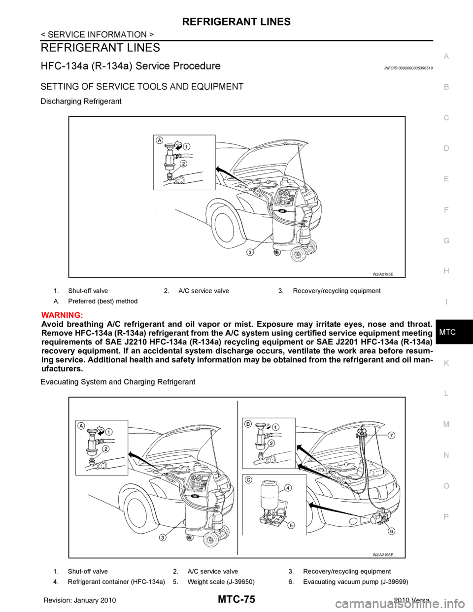
SETTING OF SERVICE TOOLS AND EQUIPMENT
Discharging Refrigerant
WARNING:
Avoid breathing A/C refrigerant and oil vapor or mist. Exposure may irritate eyes, nose and throat.
Remove HFC-134a (R-134a) refrigerant from the A/C system using certified service equipment meeting
requirements of SAE J2210 HFC-134a (R-134a) r ecycling equipment or SAE J2201 HFC-134a (R-134a)
recovery equipment. If an accidental system dischar ge occurs, ventilate the work area before resum-
ing service. Additional health and safety information may be obtain ed from the refrigerant and oil man-
ufacturers.
Evacuating System and Charging Refrigerant
1. Shut-off valve 2. A/C service valve 3. Recovery/recycling equipment
A. Preferred (best) method
WJIA2195E
1. Shut-off valve 2. A/C service valve3. Recovery/recycling equipment
4. Refrigerant container (HFC-134a) 5. Weight scale (J-39650) 6. Evacuating vacuum pump (J-39699)
WJIA2196E
Revision: January 20102010 Versa
Page 3677 of 3745

PRECAUTIONSSTC-31
< PRECAUTION > [EPS]
C
D
E
F
H I
J
K L
M A
B
STC
N
O P
5. When the repair work is completed, return the ignition switch to the ″LOCK ″ position before connecting
the battery cables. (At this time, the steering lock mechanism will engage.)
6. Perform a self-diagnosis check of al l control units using CONSULT-III.
Service Notice or Precaution for EPS SystemINFOID:0000000005602354
CAUTION:
Check or confirm the following item wh en performing the trouble diagnosis.
• Check any possible causes by interviewing the symptom and it’s condition from the customer if any
malfunction, such as EPS warn ing lamp turns ON, occurs.
• Check if air pressure and size of tires are proper, the specified part is used for the steering wheel,
and control unit is genuine part.
• Check if the connection of steer ing column assembly and steering gear assembly is proper (there is
not looseness of mounting bolts, damage of rods, boots or sealants, and leakage of grease, etc).
• Check if the wheel alignment is adjusted properly.
• Check if there is any damage or modification to su spension or body resulting in increased weight or
altered ground clearance.
• Check if installation conditions of each link and suspension are proper.
• Check if the battery voltage is proper
• Check connection conditions of each connector are proper.
• Before connecting or disconnect ing the EPS control unit har-
ness connector, turn ignition switch “OFF” and disconnect
battery ground cable. Because battery voltage is applied to
EPS control unit even if igniti on switch is turned “OFF”.
• When connecting or disconnect ing pin connectors into or
from EPS control unit, take care not to damage pin terminals
(bend or break).
When connecting pin connectors, make sure that there are no
bends or breaks on EPS control unit pin terminal.
• Before replacing EPS control unit, perform EPS control unit input/output signal inspectio n and make sure whether EPS
control unit functions properly or not. Refer to STC-20, "
Ref-
erence Value".
SEF289H
SEF291H
SDIA1848E
Revision: January 20102010 Versa
Page 3684 of 3745

ROAD WHEEL TIRE ASSEMBLYWT-7
< SERVICE INFORMATION >
C
DF
G H
I
J
K L
M A
B
WT
N
O P
ROAD WHEEL TIRE ASSEMBLY
AdjustmentINFOID:0000000005714422
BALANCING WHEELS (ADH ESIVE WEIGHT TYPE)
Preparation Before Adjustment
Remove inner and outer balance weights from the r oad wheel using releasing agent, remove double-faced
adhesive tape from the road wheel.
CAUTION:
• Be careful not scratch the road wheel during removal.
• After removing double-faced adhesive tape, wipe clean traces of releasing agent from the road
wheel.
Wheel Balance Adjustment
• If a balancer machine has an adhesive weight mode setting, select the adhesive weight mode setting and skip Step 2. below. If a balancer machine only has the clip-on (rim flange) weight mode setting, follow Step 2.
to calculate the correct size adhesive weight.
1. Set road wheel on balancer machine using the cent er hole as a guide. Start the balancer machine.
2. For tire balance machines that only have a clip-on (ri m flange) weight mode setting, follow this step to cal-
culate the correct size adhesive weight to use. When inner and outer imbalance values are shown on the
balancer machine indicator, multiply outer imbalance value by 5/3 (1.67) to determine balance weight that
should be used. Select the outer balance weight with a value closest to the calculated value above and
install in to the designated outer position of, or at the designated angle in relation to the road wheel.
a. Indicated imbalance value × 5/3 (1.67) = balance weight to be
installed
Calculation example:
23 g (0.81 oz) × 5/3 (1.67) = 38.33 g (1.35 oz) ⇒ 40 g (1.41 oz)
balance weight (closer to calculated balance weight value)
NOTE:
Note that balance weight value must be closer to the calculated
balance weight value.
Example:
37.4 ⇒ 35 g (1.23 oz)
37.5 ⇒ 40 g (1.41 oz)
3. Install balance weight in the position shown. CAUTION:
• Do not install the inner bala nce weight before installing
the outer balance weight.
• Before installing the balance weight, be sure to clean the mating surface of the road wheel.
• When installing balance weight (1) to road wheel, set it into the
grooved area (A) on the inner wall of the road wheel as shown
so that the balance weight cent er (B) is aligned with the bal-
ancer machine indication position (angle) (C).
CAUTION:
• Always use genuine NISSAN adhesive balance weights.
• Balance weights are non-re usable; always replace with
new ones.
• Do not install more than th ree sheets of balance weight.
SMA054D
JPEIC0040ZZ
Revision: January 20102010 Versa
Page 3685 of 3745

WT-8
< SERVICE INFORMATION >
ROAD WHEEL TIRE ASSEMBLY
4. If calculated balance weight value exceeds 50 g (1.76 oz), installtwo balance weight sheets in line with each other as shown.
CAUTION:
Do not install one balance weight sheet on top another.
5. Start balancer machine again.
6. Install balance weight on inner side of road wheel in the bal- ancer machine indication position (angle).
CAUTION:
Do not install more than two balance weights.
7. Start balancer machine. Make sure that inner and outer residual imbalance values are 5 g (0.17 oz) each or below.
8. If either residual imbalance value exceeds 5 g (0.17 oz), repeat installation procedures.
TIRE ROTATION
• Follow the maintenance schedule for tire rotation service intervals.
Refer to MA-7, "
General Maintenance".
• When installing the wheel, tighten wheel nuts to the specified
torque.
CAUTION:
• Do not include the T-type spare tire when rotating the tires.
• When installing wheels, tighten them diagonally by dividing
the work two to three times in order to prevent the wheels
from developing any distortion.
• Be careful not to tighten wheel nut at torque exceeding the criteria for preventing strain of disc rotor.
• Use NISSAN genuine wheel nuts for aluminum wheels.
• Perform the ID registration, after tire rotation. Refer to WT-13, "
ID Registration Procedure".
Wheel balance Dynamic (At flange) Static (At flange)
Maximum allowable un-
balance Refer to
WT-28, "
Road Wheel".
PEIA0033E
Wheel nut tightening
torque : 113 N·m (12 kg-m, 83 ft-lb)
SMA829C
Revision: January 20102010 Versa