2010 NISSAN LATIO charging
[x] Cancel search: chargingPage 3442 of 3745

HARNESSPG-59
< SERVICE INFORMATION >
C
DE
F
G H
I
J
L
M A
B
PG
N
O P
Wiring Diagram Codes (Cell Codes)INFOID:0000000005395367
Use the chart below to find out what each wiring diagram code stands for.
Refer to the wiring diagram code in the alphabetical index to find the location (page number) of each wiring
diagram.
D4 D405 W/4 : Back door lock assembly C2 D413 B/1 : Rear window defogger (-)
D4 D406 W/2 : Back door request switch F3 D414 — : Body ground
E2 D407 W/2 : High mounted stop lamp
Code Section Wiring Diagram Name
ABS BRC Anti-lock Brake System
A/C,M MTC Manual Air Conditioner
APPS1 EC Accelerator Pedal Position Sensor
A/F EC Air Fuel Ratio Sensor 1
A/FH EC Air Fuel Ratio Sensor 1 Heater
APPS2 EC Accelerator Pedal Position Sensor
APPS3 EC Accelerator Pedal Position Sensor
ASC/BS EC ASCD Brake Switch
ASC/SW EC ASCD Steering Switch
ASCBOF EC ASCD Brake Switch
ASCIND EC ASCD Indicator
AT/IND DI A/T Indicator Lamp
AUDIO AV Audio
BACK/L LT Back-up Lamp
BA/FTS AT A/T Fluid Temperature Sensor and TCM Power Supply
B/DOOR BL Back Door Opener
BRK/SW EC Brake Switch
CAN AT CAN Communication Line
CAN CVT CAN Communication Line
CAN EC CAN Communication Line
CAN LAN CAN System
CHARGE SC Charging System
CHIME DI Warning Chime
COOL/F EC Cooling Fan Control
COMBSW LT Combination Switch
COMM AV Audio Visual Communication System
CVTIND DI CVT Indicator Lamp
D/LOCK BL Power Door Lock
DEF GW Rear Window Defogger
DTRL LT Headlamp - Wi th Daytime Light System
ECTS EC Engine Coolant Temperature Sensor
ENGSS AT Engine Speed Signal
EPS STC Electronic Controlled Power Steering
ETC1 EC Electric Throttle Control Function
ETC2 EC Throttle Control Motor Relay
ETC3 EC Throttle Control Motor
F/FOG LT Front Fog Lamp
F/PUMP EC Fuel Pump
FTS AT A/T Fluid Temperature Sensor
FTS CVT CVT Fluid Temperature Sensor Circuit
FTTS EC Fuel Tank Temperature Sensor
FUEL EC Fuel Ignition System Function
Revision: January 20102010 Versa
Page 3540 of 3745

SC-1
ELECTRICAL
C
DE
F
G H
I
J
L
M
SECTION SC
A
B
SC
N
O P
CONTENTS
STARTING & CHARGING SYSTEM
SERVICE INFORMATION .. ..........................2
PRECAUTIONS .............................................. .....2
Precaution for Supplemental Restraint System
(SRS) "AIR BAG" and "SEAT BELT PRE-TEN-
SIONER" ............................................................. ......
2
Precaution Necessary for Steering Wheel Rota-
tion After Battery Disconnect ............................... ......
2
PREPARATION ...................................................4
Special Service Tool ........................................... ......4
Commercial Service Tool ..........................................4
BATTERY ............................................................5
How to Handle Battery ........................................ ......5
Trouble Diagnosis with Multitasking Battery Diag-
nostic Station ....................................................... ......
7
Removal and Installation ...........................................7
Required Procedure After Battery Disconnection ......8
STARTING SYSTEM ..........................................9
System Description .............................................. .....9
Wiring Diagram - START - .......................................11
Trouble Diagnosis with Multitasking Battery Diag-
nostic Station ...........................................................
16
Removal and Installation HR16DE ..........................19
Removal and Installation MR18DE ..........................20
CHARGING SYSTEM .......................................21
System Description ..................................................21
Wiring Diagram - CHARGE - ...................................22
Trouble Diagnosis with Multitasking Battery Diag-
nostic Station ...........................................................
22
Removal and Installation .........................................25
SERVICE DATA AND SPECIFICATIONS
(SDS) .................................................................
27
Battery .....................................................................27
Starter ......................................................................27
Generator ................................................................27
Revision: January 20102010 Versa
Page 3543 of 3745

SC-4
< SERVICE INFORMATION >
PREPARATION
PREPARATION
Special Service ToolINFOID:0000000005394855
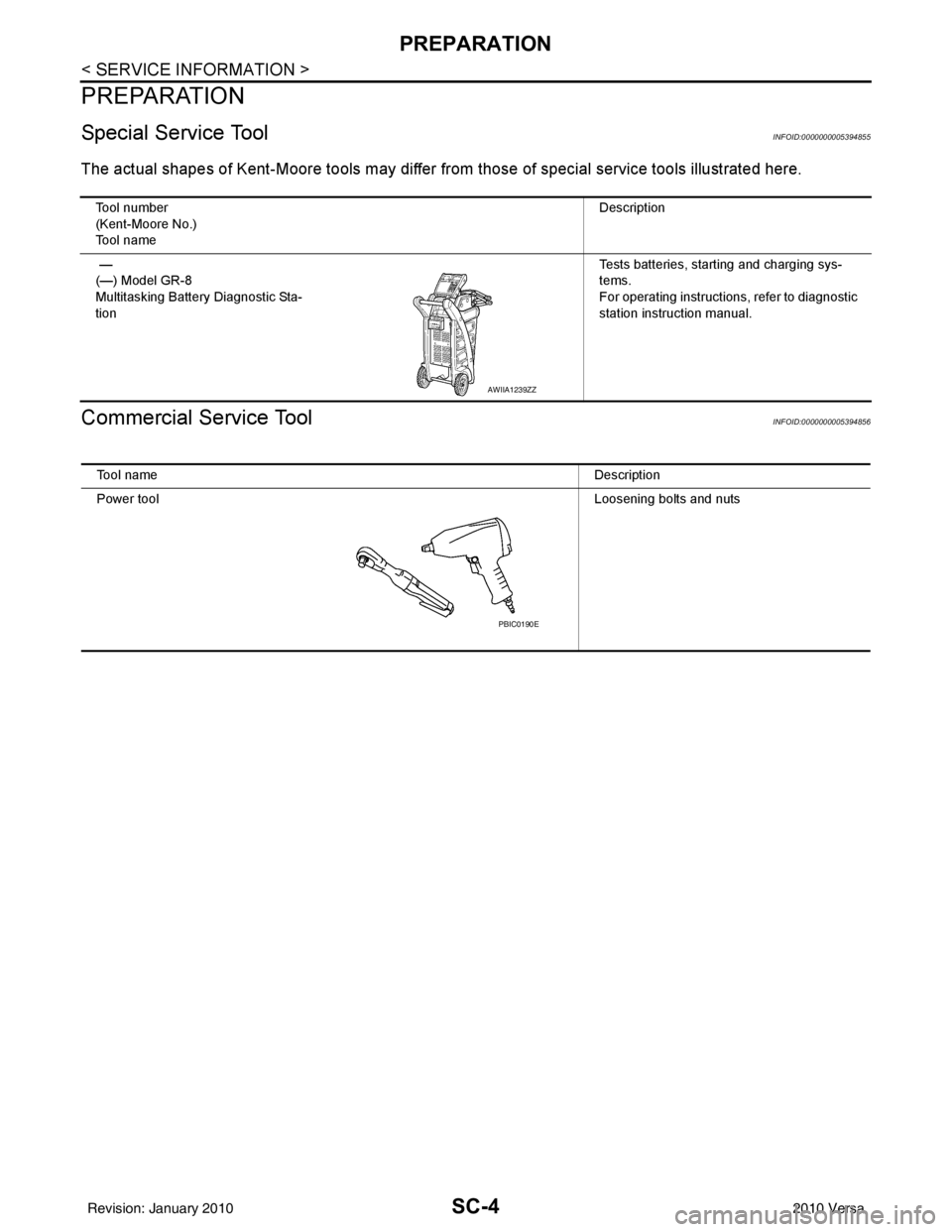
The actual shapes of Kent-Moore tools may differ from those of special service tools illustrated here.
Commercial Service ToolINFOID:0000000005394856
Tool number
(Kent-Moore No.)
Tool name Description
—
(—) Model GR-8
Multitasking Battery Diagnostic Sta-
tion Tests batteries, starting and charging sys-
tems.
For operating instructions, refer to diagnostic
station instruction manual.
AWIIA1239ZZ
Tool name
Description
Power tool Loosening bolts and nuts
PBIC0190E
Revision: January 20102010 Versa
Page 3544 of 3745

BATTERYSC-5
< SERVICE INFORMATION >
C
DE
F
G H
I
J
L
M A
B
SC
N
O P
BATTERY
How to Handle BatteryINFOID:0000000005394857
CAUTION:
• If it becomes necessary to start the engine with a booster battery and jumper cables, use a 12-volt
booster battery.
• After connecting battery cables, ensure that they are tightly clamped to battery terminals for good
contact.
• Never add distilled water through the hole used to check specific gravity.
METHODS OF PREVENTING OVER-DISCHARGE
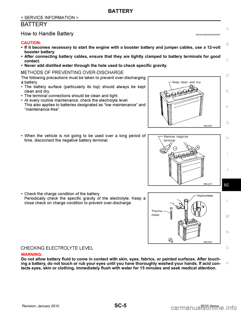
The following precautions must be taken to prevent over-discharging
a battery.
• The battery surface (particularly its top) should always be kept
clean and dry.
• The terminal connections should be clean and tight.
• At every routine maintenance, check the electrolyte level.
This also applies to batteries designated as “low maintenance” and
“maintenance-free”.
• When the vehicle is not going to be used over a long period of time, disconnect the negative battery terminal.
• Check the charge condition of the battery. Periodically check the specific gr avity of the electrolyte. Keep a
close check on charge condition to prevent over-discharge.
CHECKING ELECTROLYTE LEVEL
WARNING:
Do not allow battery fluid to come in contact with skin, eyes, fabrics, or painted surfaces. After touch-
ing a battery, do not touch or rub your eyes until yo u have thoroughly washed your hands. If acid con-
tacts eyes, skin or clothing, imme diately flush with water for 15 minutes and seek medical attention.
MEL040F
MEL041F
MEL042F
Revision: January 20102010 Versa
Page 3545 of 3745

SC-6
< SERVICE INFORMATION >
BATTERY
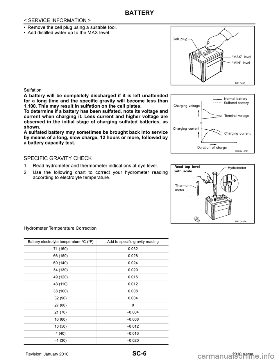
• Remove the cell plug using a suitable tool.
• Add distilled water up to the MAX level.
Sulfation
A battery will be completely discharged if it is left unattended
for a long time and the specific gravity will become less than
1.100. This may result in sulfation on the cell plates.
To determine if a battery has been sulfated, note its voltage and
current when charging it. Less current and higher voltage are
observed in the initial stage of charging sulfated batteries, as
shown.
A sulfated battery may sometimes be brought back into service
by means of a long, slow charge, 12 hours or more, followed by
a battery capacity test.
SPECIFIC GRAVITY CHECK
1. Read hydrometer and thermometer indications at eye level.
2. Use the following chart to correct your hydrometer reading
according to electrolyte temperature.
Hydrometer Temperature Correction
MEL043F
WKIA4166E
MEL042FA
Battery electrolyte temperature °C ( °F) Add to specific gravity reading
71 (160) 0.032
66 (150) 0.028
60 (140) 0.024
54 (130) 0.020
49 (120) 0.016
43 (110) 0.012
38 (100) 0.008
32 (90) 0.004
27 (80) 0
21 (70) −0.004
16 (60) −0.008
10 (50) −0.012
4 (40) −0.016
− 1 (30) −0.020
Revision: January 20102010 Versa
Page 3546 of 3745

BATTERYSC-7
< SERVICE INFORMATION >
C
DE
F
G H
I
J
L
M A
B
SC
N
O P
CHARGING THE BATTERY
CAUTION:
• Do not “quick charge” a fully discharged battery.
• Keep the battery away from open flame while it is being charged.
• When connecting the charger, connect the leads first, then turn on the charger. Do not turn on the
charger first, as this may cause a spark.
• If battery electrolyte temperature rises above 55 °C (131 °F), stop charging. Alw ays charge battery at a
temperature below 55 °C (131° F).
Charging Rates
Do not charge at more than 50 ampere rate.
NOTE:
The ammeter reading on your battery charger will automatically decrease as the battery charges. This indi-
cates that the voltage of the battery is increasing norma lly as the state of charge improves. The charging amps
indicated above refer to initial charge rate.
• If, after charging, the specific gravity of any two cells varies more than 0.050, the battery should be replaced.
Trouble Diagnosis with Multita sking Battery Diagnostic StationINFOID:0000000005394858
Refer to diagnostic station instruction manual.
Removal and InstallationINFOID:0000000005394859
REMOVAL (All except MR18DE with CVT)
1. Disconnect battery negative (1) and positive (2) terminals.
−7 (20) −0.024
− 12 (10) −0.028
− 18 (0) −0.032
Corrected specific gravity Approximate charge condition
1.260 - 1.280 Fully charged
1.230 - 1.250 3/4 charged
1.200 - 1.220 1/2 charged
1.170 - 1.190 1/4 charged
1.140 - 1.160 Almost discharged
1.110 - 1.130 Completely discharged
Battery electrolyte temperature °
C (°F) Add to specific gravity reading
Amps Time
50 1 hour
25 2 hours
10 5 hours
5 10 hours
AWMIA0053ZZ
Revision: January 20102010 Versa
Page 3560 of 3745

CHARGING SYSTEMSC-21
< SERVICE INFORMATION >
C
DE
F
G H
I
J
L
M A
B
SC
N
O P
CHARGING SYSTEM
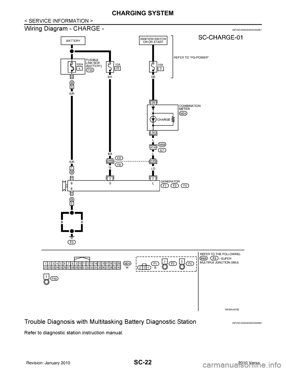
System DescriptionINFOID:0000000005394866
The generator provides DC voltage to operate the vehicl e's electrical system and to keep the battery charged.
The voltage output is controlled by the IC regulator.
Power is supplied at all times to generator terminal 3 through
• 10A fuse (No. 29, located in the fuse and fusible link box).
Power is supplied through terminal 1 to charge the batte ry and operate the vehicle's electrical system. Output
voltage is monitored at terminal 3 by the IC regulator. The charging circuit is protected by the 120A fusible link
[letter a , located in the fusible link box (battery)].
Ground is supplied
• to generator terminal 5
• through body ground F5, and
• through the generator case to the cylinder block
With the ignition switch in the ON or START position, power is supplied
• through 10A fuse [No. 3, located in the fuse block (J/B)]
• to combination meter terminal 28 for the charge warning lamp.
The IC regulator controls ground to terminal 38 of the combination meter through terminal 2 of the generator.
When the ignition is turned on and power becomes availabl e at terminal 2, this "wakes up" the regulator. The
regulator monitors charge output and grounds terminal 2 or leaves it open depending on charge output. With
power and ground supplied, the charge warning lamp will il luminate. When the generator is providing sufficient
voltage, the ground is opened and the charge warning lamp will go off.
If the charge warning lamp illuminates with the engine running, a malfunction is indicated.
Revision: January 20102010 Versa
Page 3561 of 3745

SC-22
< SERVICE INFORMATION >
CHARGING SYSTEM
Wiring Diagram - CHARGE -
INFOID:0000000005394867
Trouble Diagnosis with Multitas king Battery Diagnostic StationINFOID:0000000005394868
Refer to diagnostic station instruction manual.
WKWA4970E
Revision: January 20102010 Versa