Page 2796 of 3745

IP-12
< ON-VEHICLE REPAIR >
INSTRUMENT PANEL ASSEMBLY
Removal and Installation
INFOID:0000000005396857
INSTRUMENT PANEL ASSEMBLY
Removal
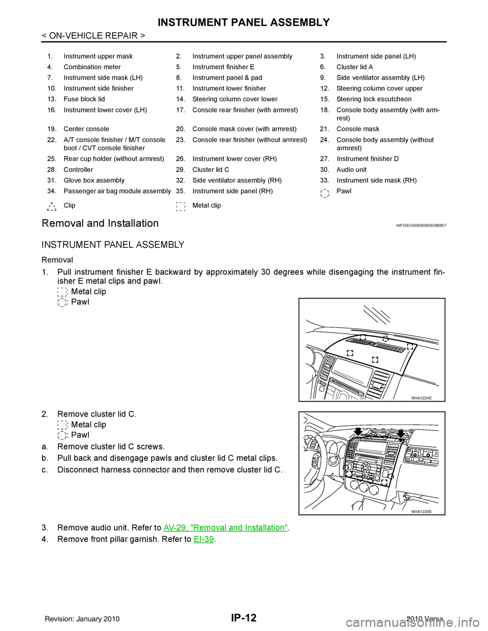
1. Pull instrument finisher E backward by approximately 30 degrees while disengaging the instrument fin- isher E metal clips and pawl.
: Metal clip
: Pawl
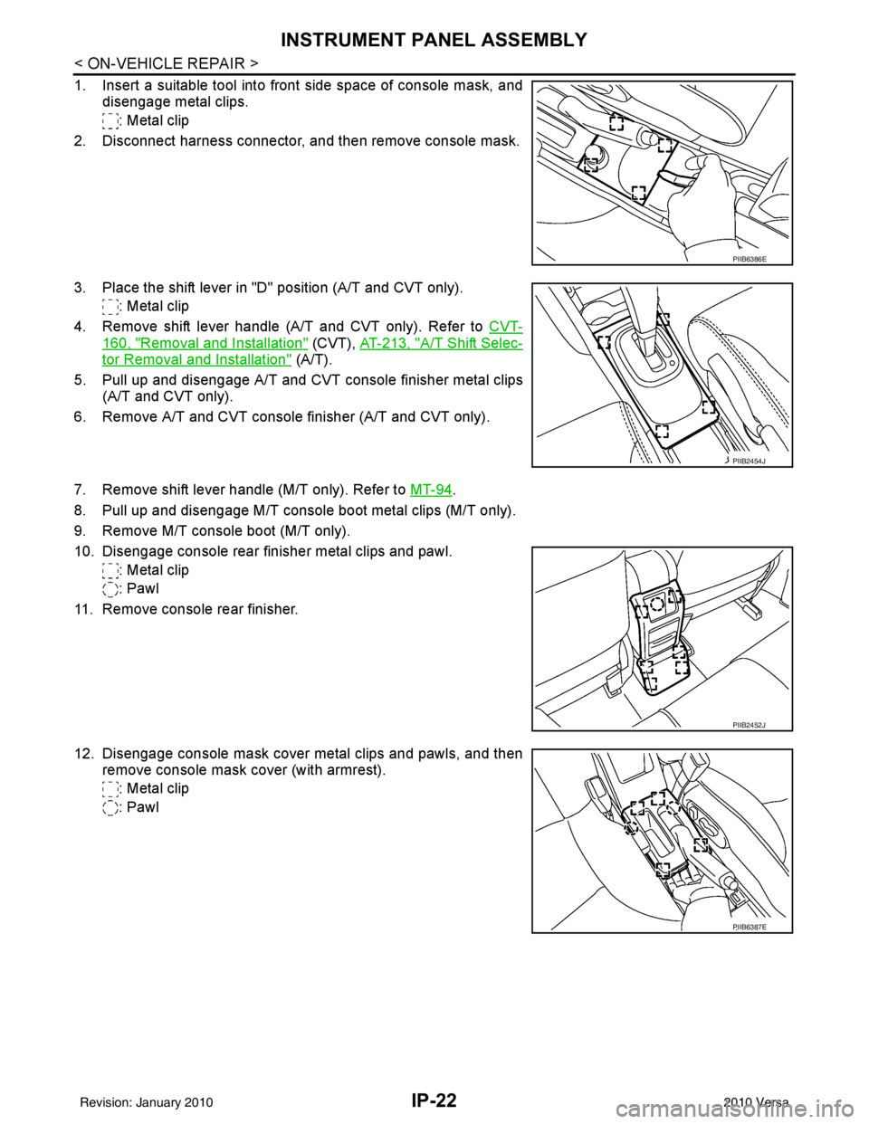
2. Remove cluster lid C. : Metal clip
: Pawl
a. Remove cluster lid C screws.
b. Pull back and disengage pawls and cluster lid C metal clips.
c. Disconnect harness connector and then remove cluster lid C.
3. Remove audio unit. Refer to AV-29, "
Removal and Installation".
4. Remove front pillar garnish. Refer to EI-39
.
1. Instrument upper mask 2. Instrument upper panel assembly 3. Instrument side panel (LH)
4. Combination meter 5. Instrument finisher E 6. Cluster lid A
7. Instrument side mask (LH) 8. Instrument panel & pad 9. Side ventilator assembly (LH)
10. Instrument side finisher 11. Instrument lower finisher 12. Steering column cover upper
13. Fuse block lid 14. Steering column cover lower 15. Steering lock escutcheon
16. Instrument lower cover (LH) 17. Console rear finisher (with armrest) 18. Console body assembly (with arm- rest)
19. Center console 20. Console mask cover (with armrest) 21. Console mask
22. A/T console finisher / M/T console boot / CVT console finisher 23. Console rear finisher (without armrest) 24. Console body assembly (without
armrest)
25. Rear cup holder (without armrest) 26. Instrument lower cover (RH) 27. Instrument finisher D
28. Controller 29. Cluster lid C 30. Audio unit
31. Glove box assembly 32. Side ventilator assembly (RH) 33. Instrument side mask (RH)
34. Passenger air bag module assembly 35. Instrument side panel (RH) Pawl
Clip Metal clip
WIIA1224E
WIIA1225E
Revision: January 20102010 Versa
Page 2806 of 3745

IP-22
< ON-VEHICLE REPAIR >
INSTRUMENT PANEL ASSEMBLY
1. Insert a suitable tool into front side space of console mask, anddisengage metal clips.
: Metal clip
2. Disconnect harness connector, and then remove console mask.
3. Place the shift lever in "D" position (A/T and CVT only). : Metal clip
4. Remove shift lever handle (A/T and CVT only). Refer to CVT-
160, "Removal and Installation" (CVT), AT-213, "A/T Shift Selec-
tor Removal and Installation" (A/T).
5. Pull up and disengage A/T and CVT console finisher metal clips (A/T and CVT only).
6. Remove A/T and CVT console finisher (A/T and CVT only).
7. Remove shift lever handle (M/T only). Refer to MT-94
.
8. Pull up and disengage M/T console boot metal clips (M/T only).
9. Remove M/T console boot (M/T only).
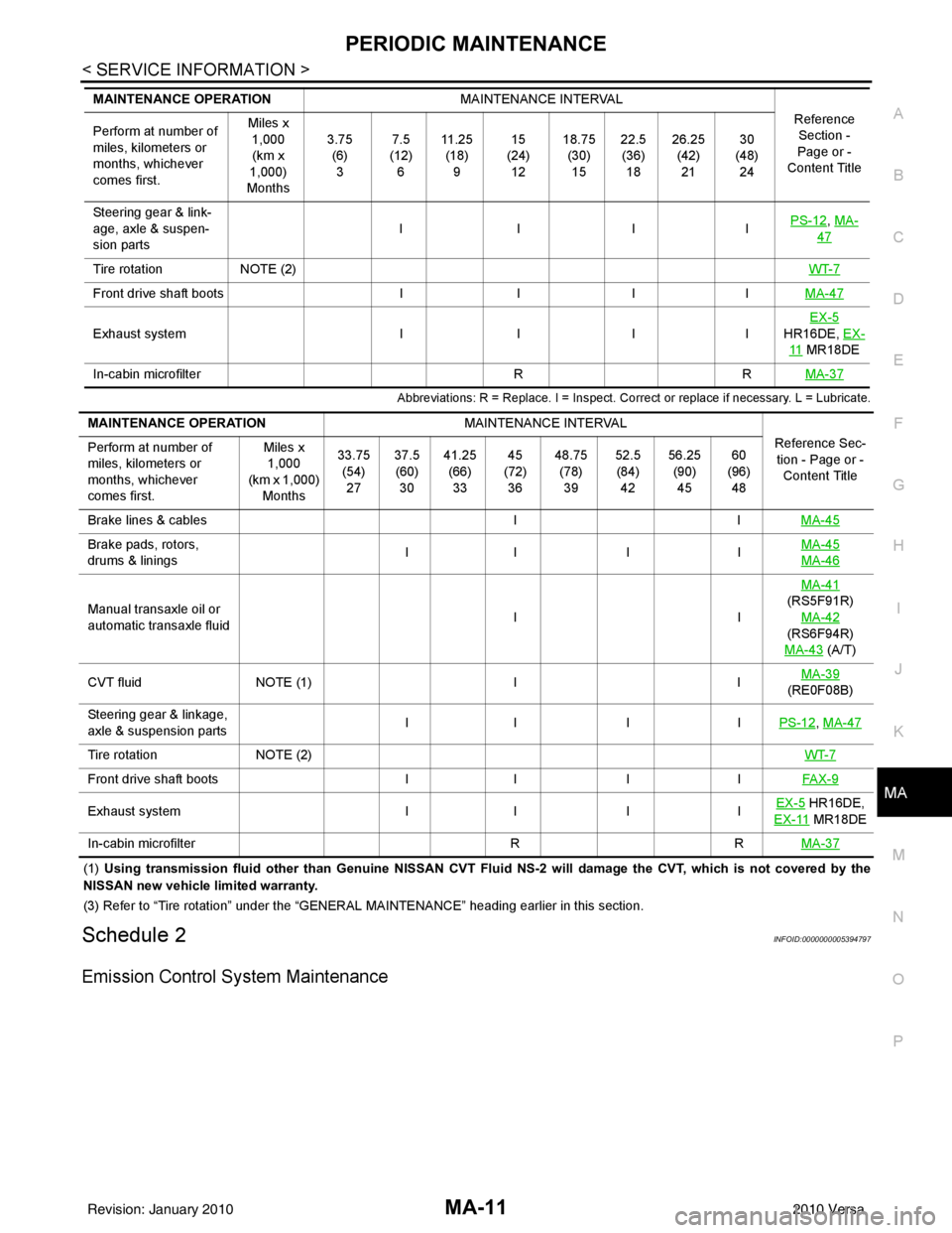
10. Disengage console rear finisher metal clips and pawl. : Metal clip
: Pawl
11. Remove console rear finisher.
12. Disengage console mask cover metal clips and pawls, and then remove console mask cover (with armrest).
: Metal clip
: Pawl
PIIB6386E
PIIB2454J
PIIB2452J
PIIB6387E
Revision: January 20102010 Versa
Page 3146 of 3745

PERIODIC MAINTENANCEMA-11
< SERVICE INFORMATION >
C
DE
F
G H
I
J
K
M A
B
MA
N
O P
Abbreviations: R = Replace. I = Inspect. Corr ect or replace if necessary. L = Lubricate.
(1) Using transmission fluid other than Genuine NISSAN CVT Fluid NS-2 will damage the CVT, which is not covered by the
NISSAN new vehicle limited warranty.
(3) Refer to “Tire rotation” under the “GENERAL MAINTENANCE” heading earlier in this section.
Schedule 2INFOID:0000000005394797
Emission Control System Maintenance
Steering gear & link-
age, axle & suspen-
sion parts IIII
PS-12, MA-
47
Tire rotation
NOTE (2) WT-7
Front drive shaft bootsIIIIMA-47
Exhaust system IIIIEX-5
HR16DE, EX-
11 MR18DE
In-cabin microfilter RRMA-37
MAINTENANCE OPERATION MAINTENANCE INTERVAL
Reference Section -
Page or -
Content Title
Perform at number of
miles, kilometers or
months, whichever
comes first. Miles x
1,000
(km x
1,000)
Months 3.75
(6)3 7.5
(12) 6 11 . 2 5
(18) 9 15
(24) 12 18.75
(30)15 22.5
(36) 18 26.25
(42)21 30
(48) 24
MAINTENANCE OPERATION MAINTENANCE INTERVAL
Reference Sec-tion - Page or - Content Title
Perform at number of
miles, kilometers or
months, whichever
comes first. Miles x
1,000
(km x 1,000) Months 33.75
(54)27 37.5
(60) 30 41.25
(66)33 45
(72) 36 48.75
(78)39 52.5
(84) 42 56.25
(90)45 60
(96) 48
Brake lines & cables IIMA-45
Brake pads, rotors,
drums & linings II I I MA-45
MA-46
Manual transaxle oil or
automatic transaxle fluid IIMA-41
(RS5F91R) MA-42
(RS6F94R)
MA-43
(A/T)
CVT fluid NOTE (1) IIMA-39
(RE0F08B)
Steering gear & linkage,
axle & suspension parts II I I
PS-12
, MA-47
Tire rotationNOTE (2) WT-7
Front drive shaft bootsII IIFAX-9
Exhaust system II IIEX-5 HR16DE,
EX-11
MR18DE
In-cabin microfilter RRMA-37
Revision: January 20102010 Versa
Page 3182 of 3745
CHASSIS AND BODY MAINTENANCEMA-47
< SERVICE INFORMATION >
C
DE
F
G H
I
J
K
M A
B
MA
N
O P
AXLE AND SUSPENSION PARTS : Axle and Suspension PartsINFOID:0000000005394849
Check front and rear axle and suspension parts for excessive play,
cracks, wear or other damage.
• Shake each wheel to check for excessive play.
• Check wheel bearings for smooth operation.
• Check axle and suspension nuts and bolts for looseness.
• Check strut (shock absorber) for oil leakage or other damage.
• Check suspension ball joint for grease leakage and ball joint dust
cover for cracks or other damage.
DRIVE SHAFT
DRIVE SHAFT : Drive ShaftINFOID:0000000005394850
Check boot and drive shaft for cracks, wear, damage and grease
leakage.
LOCKS, HINGES AND HOOD LATCH
SMA525A
SFA392B
SDIA1190J
Revision: January 20102010 Versa
Page 3199 of 3745
CONTROL LINKAGEMT-15
< SERVICE INFORMATION > [RS5F91R]
D
E
F
G H
I
J
K L
M A
B
MT
N
O P
• Move the shift lever to the neutral position.
• Securely assemble each of the cables to each select lever of control shaft, mounting bracket, and the M/T
shift selector assembly.
• Be careful about the installation direction, and push shift lever han- dle onto shift lever.
CAUTION:
Do not reuse shift lever handle.
• Make sure that the front/rear claws (1) of M/T shift selector assem- bly are in contact with flange of the floor (2).
InspectionINFOID:0000000005397173
Inspect the following items:
• When shift lever is selected to 1st-2nd side and 5th-reverse side, confirm shift lever returns to neutral posi-tion smoothly.
• When the shift lever is shifted to each position, make sure there is no binding or disconnection in each boot.
PCIB1509E
PCIB1510E
Revision: January 20102010 Versa
Page 3243 of 3745
![NISSAN LATIO 2010 Service Repair Manual CONTROL LINKAGEMT-59
< SERVICE INFORMATION > [RS6F94R]
D
E
F
G H
I
J
K L
M A
B
MT
N
O P
b. Pull the release button (1) of select cable (2) and then remove it from control shaft select lever (3).
5. Mo NISSAN LATIO 2010 Service Repair Manual CONTROL LINKAGEMT-59
< SERVICE INFORMATION > [RS6F94R]
D
E
F
G H
I
J
K L
M A
B
MT
N
O P
b. Pull the release button (1) of select cable (2) and then remove it from control shaft select lever (3).
5. Mo](/manual-img/5/57358/w960_57358-3242.png)
CONTROL LINKAGEMT-59
< SERVICE INFORMATION > [RS6F94R]
D
E
F
G H
I
J
K L
M A
B
MT
N
O P
b. Pull the release button (1) of select cable (2) and then remove it from control shaft select lever (3).
5. Move shift lever to neutral position.
6. Remove shift lever handle.
7. Remove center console assembly. Refer to IP-12, "
Removal and
Installation".
8. Remove M/T shift selector assembly bolts.
9. Remove exhaust front tube, cent er muffler and heat plate. Refer
to EX-11, "
Removal and Installation".
10. Remove cable support bracket.
11. Remove select cable and shif t cable from cable bracket.
12. Remove M/T shift selector assembly from the vehicle.
INSTALLATION
Installation is in the reverse order of removal.
NOTE:
Self tapping bolts are used to attach cables to the clutch housing.
• Securely assemble each cable and lever of control shaft.
• Be careful about the installation direction, and push shift lever han- dle onto shift lever.
CAUTION:
Do not reuse shift lever handle.
• Make sure that the front/rear claws (1) of M/T shift selector assem- bly are in contact with flange of the floor (2).
• When shift lever is selected to 1st-2nd side and 5th-6th side, con- firm shift lever returns to neutral position smoothly.
• When shift lever is shifted to each position, make sure there is no
binding or disconnection in each boot.
• Move stopper (1) to lock position when installing the shift cable onto the control shaft shift lever.
WCIA0606E
SCIA7630E
PCIB1510E
SCIA7846E
Revision: January 20102010 Versa
Page 3462 of 3745
PS-4
< SERVICE INFORMATION >
PREPARATION
PREPARATION
Special Service ToolINFOID:0000000005396931
The actual shapes of Kent-Moore tools may differ from thos e of special tools illustrated here.
Commercial Service ToolINFOID:0000000005396932
Tool number
(Kent-Moore No.)
Tool name Description
ST3127S000
(J-25742-1)
Preload gauge
(J-25765-A)
1. GG91030000
Torque wrench
2. HT62940000
(—)
Socket adapter (1/2")
3. HT62900000
(—)
Socket adapter (3/8") Inspecting rotating torque for steering column
assembly and pinion assembly
KV40107300
(—)
Boot Band crimping tool Installing boot bands
KV48103400
(—)
Preload adapter Inspecting of rotating torque for pinion assem-
bly
—
(J-44372)
Pull gauge Measuring steering wheel turning force and
ball joint swinging force
S-NT541
ZZA1229D
ZZA0824D
LST024
Tool number
Tool name
Description
Power tool Removing nuts and bolts
PBIC0190E
Revision: January 20102010 Versa
Page 3471 of 3745

POWER STEERING GEARPS-13
< SERVICE INFORMATION >
C
DE
F
H I
J
K L
M A
B
PS
N
O P
CAUTION:
Clean steering gear assembly with kerosene before disassembling.
DISASSEMBLY
1. Loosen outer socket lock nut, and then re move outer socket from inner socket.
2. Remove boot clamp, and then remove boot from inner socket. CAUTION:
Do not damage inner socket an d gear housing assembly when re moving boot. Inner socket and
gear housing assembly must be replaced if inne r socket and gear housing assembly are damaged
because it may allow foreign material to enter.
3. Remove inner socket from rack assembly while holdi ng the flat portion of the rack next to the inner socket
using a suitable tool.
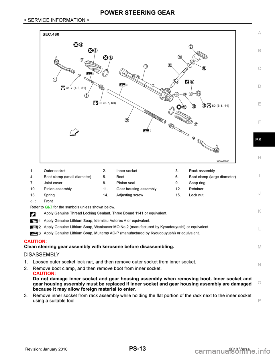
1. Outer socket 2. Inner socket 3. Rack assembly
4. Boot clamp (small diameter) 5. Boot 6. Boot clamp (large diameter)
7. Joint cover 8. Pinion seal 9. Snap ring
10. Pinion assembly 11. Gear housing assembly 12. Retainer
13. Spring 14. Adjusting screw 15. Lock nut
⇐ :Front
Refer to GI-7
for the symbols unless shown below.
: Apply Genuine Thread Locking Sealant, Three Bound 1141 or equivalent.
:1 Apply Genuine Lithium Soap, Idemitsu Autorex A or equivalent.
:2 Apply Genuine Lithium Soap, Wanlouver MO No.2 (manufactured by Kyoudouyushi) or equivalent.
:3 Apply Genuine Lithium Soap, Multemp AC-P (manufactured by Kyoudouyushi) or equivalent.
WGIA0186E
Revision: January 20102010 Versa