2010 NISSAN LATIO suspension
[x] Cancel search: suspensionPage 3146 of 3745
PERIODIC MAINTENANCEMA-11
< SERVICE INFORMATION >
C
DE
F
G H
I
J
K
M A
B
MA
N
O P
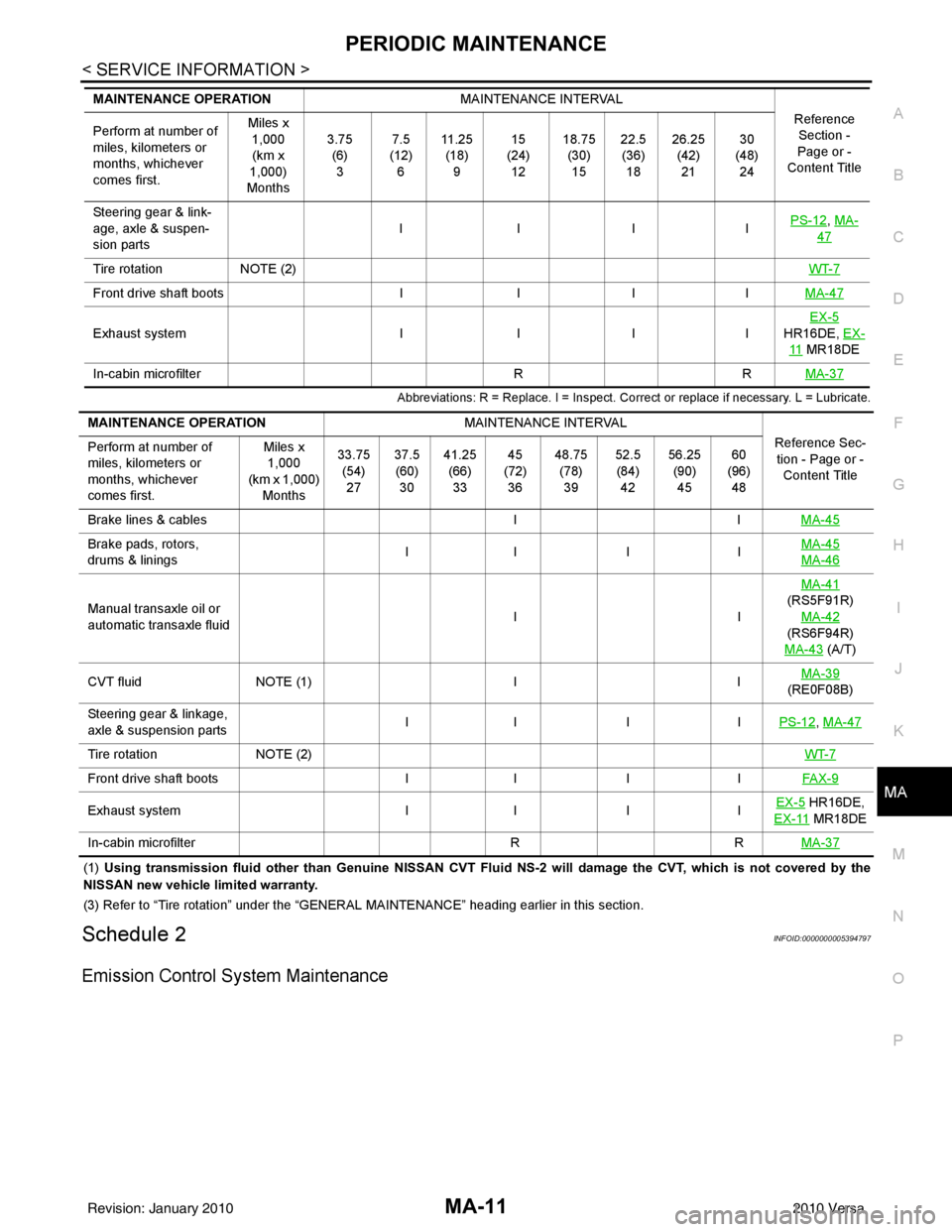
Abbreviations: R = Replace. I = Inspect. Corr ect or replace if necessary. L = Lubricate.
(1) Using transmission fluid other than Genuine NISSAN CVT Fluid NS-2 will damage the CVT, which is not covered by the
NISSAN new vehicle limited warranty.
(3) Refer to “Tire rotation” under the “GENERAL MAINTENANCE” heading earlier in this section.
Schedule 2INFOID:0000000005394797
Emission Control System Maintenance
Steering gear & link-
age, axle & suspen-
sion parts IIII
PS-12, MA-
47
Tire rotation
NOTE (2) WT-7
Front drive shaft bootsIIIIMA-47
Exhaust system IIIIEX-5
HR16DE, EX-
11 MR18DE
In-cabin microfilter RRMA-37
MAINTENANCE OPERATION MAINTENANCE INTERVAL
Reference Section -
Page or -
Content Title
Perform at number of
miles, kilometers or
months, whichever
comes first. Miles x
1,000
(km x
1,000)
Months 3.75
(6)3 7.5
(12) 6 11 . 2 5
(18) 9 15
(24) 12 18.75
(30)15 22.5
(36) 18 26.25
(42)21 30
(48) 24
MAINTENANCE OPERATION MAINTENANCE INTERVAL
Reference Sec-tion - Page or - Content Title
Perform at number of
miles, kilometers or
months, whichever
comes first. Miles x
1,000
(km x 1,000) Months 33.75
(54)27 37.5
(60) 30 41.25
(66)33 45
(72) 36 48.75
(78)39 52.5
(84) 42 56.25
(90)45 60
(96) 48
Brake lines & cables IIMA-45
Brake pads, rotors,
drums & linings II I I MA-45
MA-46
Manual transaxle oil or
automatic transaxle fluid IIMA-41
(RS5F91R) MA-42
(RS6F94R)
MA-43
(A/T)
CVT fluid NOTE (1) IIMA-39
(RE0F08B)
Steering gear & linkage,
axle & suspension parts II I I
PS-12
, MA-47
Tire rotationNOTE (2) WT-7
Front drive shaft bootsII IIFAX-9
Exhaust system II IIEX-5 HR16DE,
EX-11
MR18DE
In-cabin microfilter RRMA-37
Revision: January 20102010 Versa
Page 3147 of 3745

MA-12
< SERVICE INFORMATION >
PERIODIC MAINTENANCE
Abbreviations: R = Replace. I = Inspect. Correct or replace if necessary. [ ]: At the mileage intervals only
(1) After 60,000 miles (96,000 km) or 48 months, inspect every 15,000 miles (24,000 km) or 12 months. Replace the drive belt if found
damaged or if the auto belt tensioner reading reaches the maximum limit.
(2) Maintenance-free item.
(3) After 60,000 miles (96,000 km) or 48 months, replace every 30,000 miles (48,000 km) or 24 months.
(4) Periodic maintenance is not required. However, if valve noise increases, inspect valve clearance.
Maintenance items and intervals with “*” are recommended by NISSAN for reliab le vehicle operation. The owner need not perform such
maintenance in order to maintain the emission warranty or manufacturer recall liability. Other maintenance items and intervals are
required.
Chassis and Body Maintenance
Abbreviations: R = Replace. I = Inspect. Correct or replace if necessary. L = Lubricate.
MAINTENANCE OPERATION MAINTENANCE INTERVAL
Reference
Section - Page
or - Content Ti- tle
Perform at number of miles,
kilometers or months, which-
ever comes first. Miles x
1,000
(km x
1,000)
Months 7.5
(12) 6 15
(24) 12 22.5
(36) 18 30
(48) 24 37.5
(60) 30 45
(72) 36 52.5
(84) 42 60
(96) 48
Drive belt NOTE (1) I*EM-14
(HR)
EM-132
(MR)
Air cleaner filter [R][R]EM-17
(HR)
EM-136
(MR)
EVAP vapor lines I*I*MA-25
(HR)
MA-36
(MR)
Fuel lines I*I*FL-5
Fuel filter NOTE (2) —
Engine coolant NOTE (3) R*CO-12
(HR)
CO-36
(MR)
Engine oil RR R RRRRR LU-8
(HR)
LU-18
(MR)
Engine oil filter (Use genuine
oil filter or equivalent.) RR R RRRRR LU-9
(HR)
LU-20
(MR)
Spark plugs (Iridium/plati-
num - tipped type) Replace every 105,000 miles (169,000 km) EM-18
(HR)
EM-149
(MR)
Intake and exhaust valve
clearance* NOTE (4)
EM-114
(HR)
EM-223
(MR)
MAINTENANCE OPERATION MAINTENANCE INTERVAL
Reference Sec-
tion - Page or -
Content Title
Perform at number of miles, kilo-
meters or months, whichever
comes first. Miles x 1,000
(km x 1,000)
Months 7.5
(12)
6 15
(24)
12 22.5
(36)
18 30
(48)
24 37.5
(60)
30 45
(72)
36 52.5
(84)
42 60
(96)
48
B ra ke lin e s & cab le s IIII MA-45
Brake pads, rotors, drums & lin-
ings IIII
MA-45
MA-46
Manual transaxle oil or automatic
transaxle fluid IIIIMT-11
(RS5F91R)
MT-54
(RS6F94R)
AT- 1 7
(A/T)
C VT flu id NO TE (1) IIII CVT-15
(RE0F08B)
Steering gear & linkage, axle &
suspension parts II
PS-12
, MA-47
Tire rotation NOTE (2) WT-7
Fro n t d riv e s ha ft b oo ts IIII MA-47
Revision: January 20102010 Versa
Page 3181 of 3745
MA-46
< SERVICE INFORMATION >
CHASSIS AND BODY MAINTENANCE
DRUM BRAKE : Inspection
INFOID:0000000005394848
INSPECTION
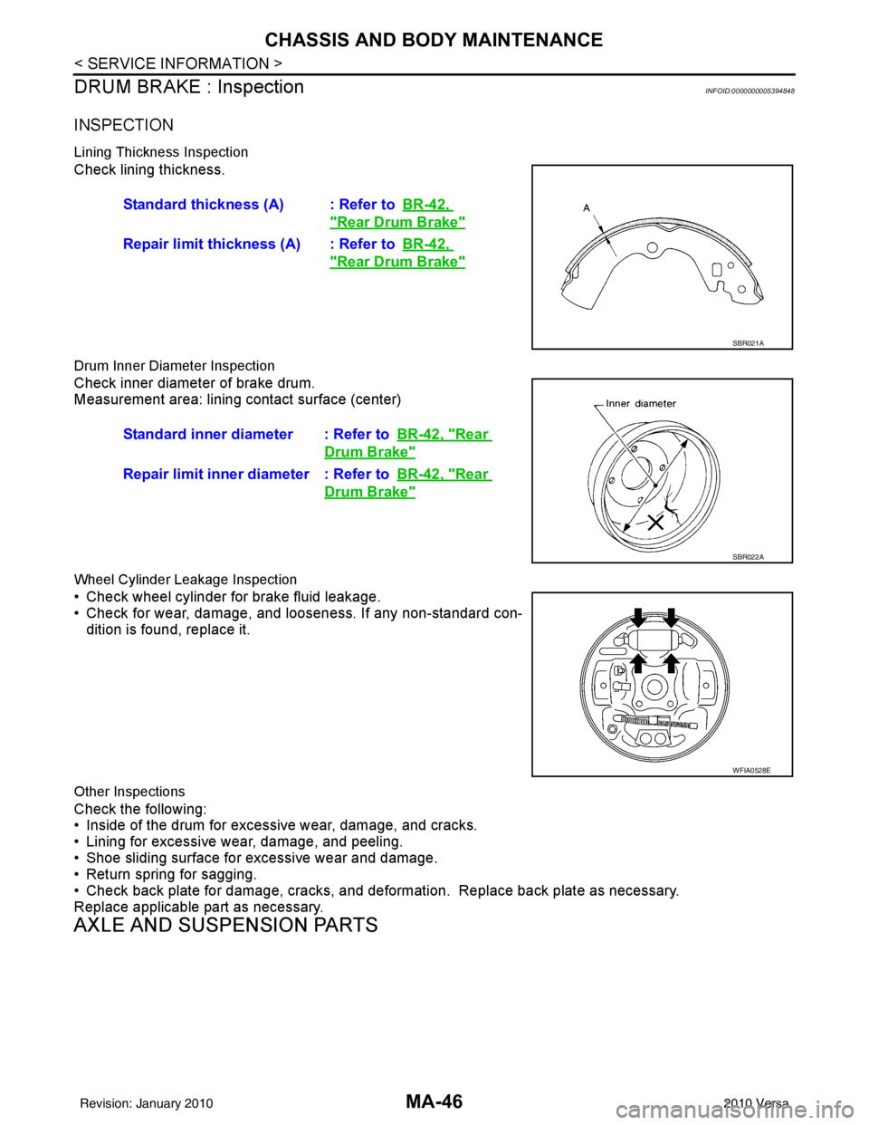
Lining Thickness Inspection
Check lining thickness.
Drum Inner Diameter Inspection
Check inner diameter of brake drum.
Measurement area: lining contact surface (center)
Wheel Cylinder Leakage Inspection
• Check wheel cylinder for brake fluid leakage.
• Check for wear, damage, and looseness. If any non-standard con- dition is found, replace it.
Other Inspections
Check the following:
• Inside of the drum for excessive wear, damage, and cracks.
• Lining for excessive wear, damage, and peeling.
• Shoe sliding surface for excessive wear and damage.
• Return spring for sagging.
• Check back plate for damage, cracks, and deforma tion. Replace back plate as necessary.
Replace applicable part as necessary.
AXLE AND SUSPENSION PARTS
Standard thickness (A) : Refer to BR-42,
"Rear Drum Brake"
Repair limit thickness (A) : Refer toBR-42,
"Rear Drum Brake"
SBR021A
Standard inner diameter : Refer toBR-42, "Rear
Drum Brake"
Repair limit inner diameter : Refer toBR-42, "Rear
Drum Brake"
SBR022A
WFIA0528E
Revision: January 20102010 Versa
Page 3182 of 3745
CHASSIS AND BODY MAINTENANCEMA-47
< SERVICE INFORMATION >
C
DE
F
G H
I
J
K
M A
B
MA
N
O P
AXLE AND SUSPENSION PARTS : Axle and Suspension PartsINFOID:0000000005394849
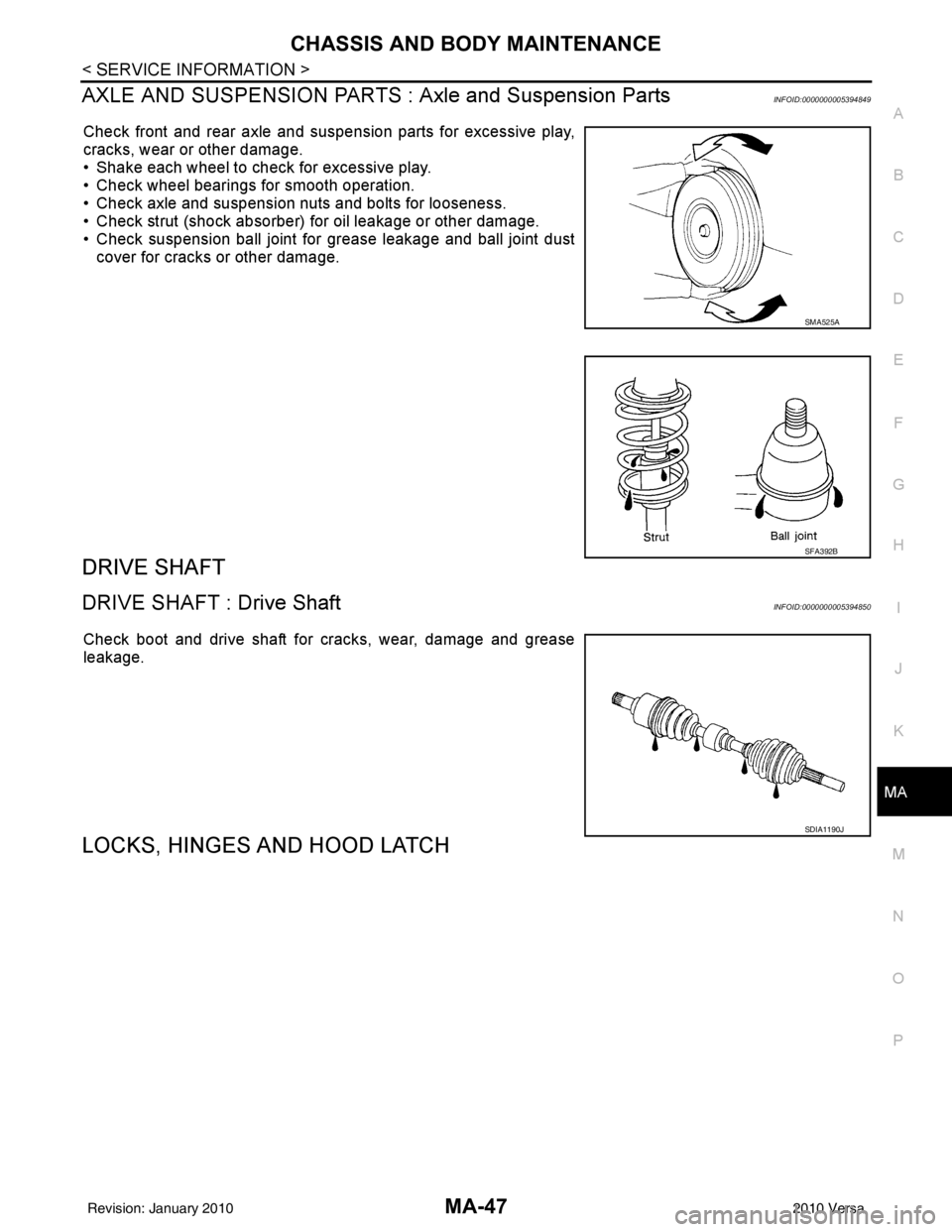
Check front and rear axle and suspension parts for excessive play,
cracks, wear or other damage.
• Shake each wheel to check for excessive play.
• Check wheel bearings for smooth operation.
• Check axle and suspension nuts and bolts for looseness.
• Check strut (shock absorber) for oil leakage or other damage.
• Check suspension ball joint for grease leakage and ball joint dust
cover for cracks or other damage.
DRIVE SHAFT
DRIVE SHAFT : Drive ShaftINFOID:0000000005394850
Check boot and drive shaft for cracks, wear, damage and grease
leakage.
LOCKS, HINGES AND HOOD LATCH
SMA525A
SFA392B
SDIA1190J
Revision: January 20102010 Versa
Page 3463 of 3745
NOISE, VIBRATION AND HARSHNESS (NVH) TROUBLESHOOTINGPS-5
< SERVICE INFORMATION >
C
DE
F
H I
J
K L
M A
B
PS
N
O P
NOISE, VIBRATION AND HARSHN ESS (NVH) TROUBLESHOOTING
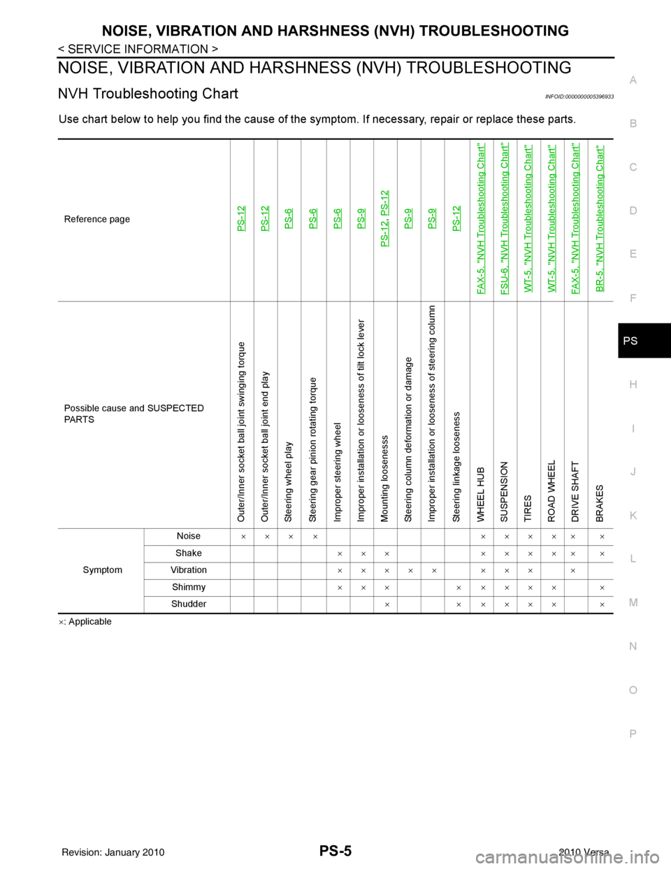
NVH Troubleshooting ChartINFOID:0000000005396933
Use chart below to help you find the cause of the symptom. If necessary, repair or replace these parts.
×: ApplicableReference page
PS-12PS-12PS-6PS-6PS-6PS-9
PS-12
,
PS-12PS-9PS-9PS-12
FAX-5, "
NVH Troubleshooting Chart
"
FSU-6, "
NVH Troubleshooting Chart
"
WT-5, "
NVH Troubleshooting Chart
"
WT-5, "
NVH Troubleshooting Chart
"
FAX-5, "
NVH Troubleshooting Chart
"
BR-5, "
NVH Troubleshooting Chart
"
Possible cause and SUSPECTED
PA R T S
Outer/Inner socket ball joint swinging torque
Outer/Inner socket ball joint end play
Steering wheel play
Steering gear pinion rotating torque
Improper steering wheel
Improper installation or looseness of tilt lock lever
Mounting loosenesss
Steering column deformation or damage
Improper installation or looseness of steering column
Steering linkage looseness
WHEEL HUB
SUSPENSION
TIRES
ROAD WHEEL
DRIVE SHAFT
BRAKES
Symptom Noise
××× × ××××× ×
Shake ×××××××× ×
Vibration ××××× ××× ×
Shimmy ×××× ×××× ×
Shudder ×× ×××× ×
Revision: January 20102010 Versa
Page 3464 of 3745
PS-6
< SERVICE INFORMATION >
STEERING WHEEL
STEERING WHEEL
On-Vehicle Inspection and ServiceINFOID:0000000005396934
CHECKING CONDITION OF INSTALLATION
• Check installation conditions of steering gear assembly, front suspension assembly, axle and steering col-
umn assembly.
• Check if movement exists when steering wheel is mo ved up and down, to the left and right and to the axial
direction.
• Check steering gear assembly mounting bolts and nuts for looseness. Refer to PS-12, "
Removal and Instal-
lation".
CHECKING STEERING WHEEL PLAY
• Turn steering wheel so that front wheels come to the straight-ahead position. Start engine and lightly turn
steering wheel to the left and right until front wheels start to move. Measure steering wheel movement on the
outer circumference.
• When the measurement value is outside the standard val ue, check backlash for each joint of steering col-
umn assembly and installation condition of steering gear assembly.
CHECKING NEUTRAL POSITION STEERING WHEEL
• Make sure that steering gear assembly, steering column assembly and steering wheel are installed in the correct position.
• Perform neutral position inspection after wheel alignment. Refer to SRS-2, "
Precaution for Supplemental
Restraint System (SRS) "AIR BAG" and "SEAT BELT PRE-TENSIONER"".
• Set vehicle to the straight-ahead position and c onfirm steering wheel is in the neutral position.
• Loosen outer socket lock nut and turn inner socket to left and right equally to make fine adjustments if steer-
ing wheel is not in the neutral position.
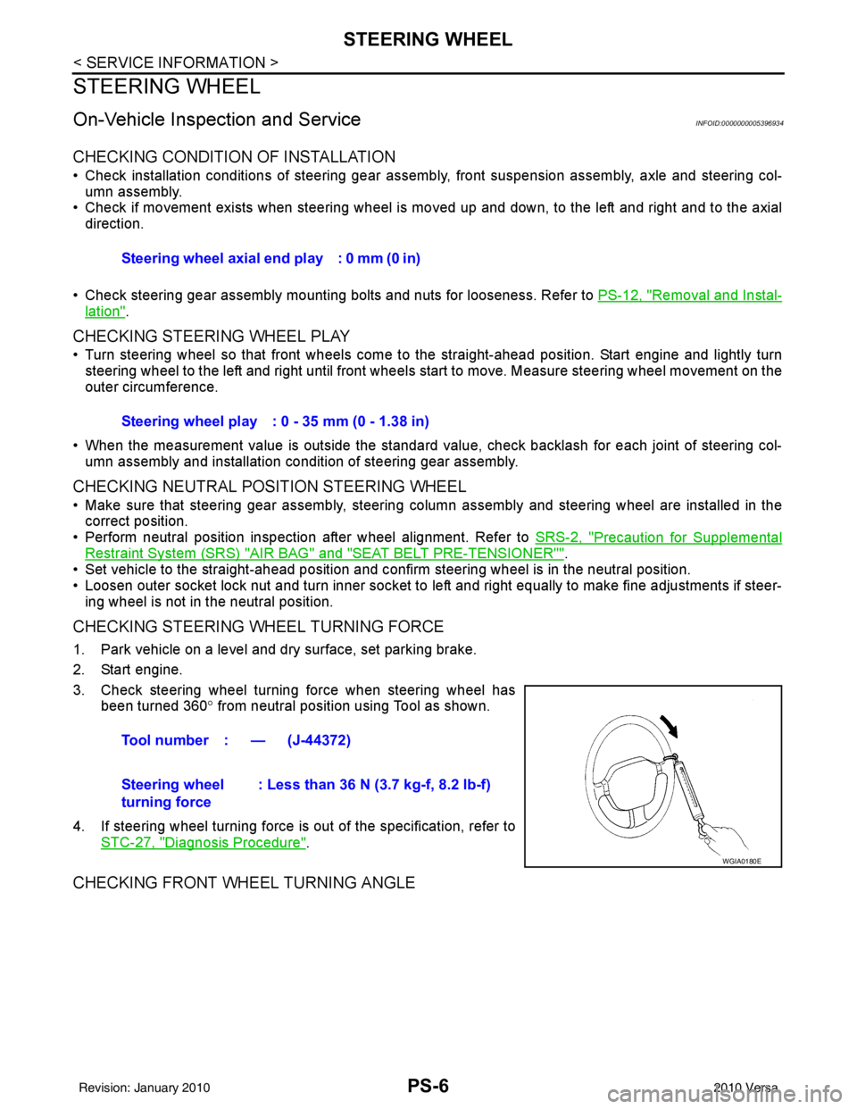
CHECKING STEERING WHEEL TURNING FORCE
1. Park vehicle on a level and dry surface, set parking brake.
2. Start engine.
3. Check steering wheel turning force when steering wheel has
been turned 360 ° from neutral position using Tool as shown.
4. If steering wheel turning force is out of the specification, refer to STC-27, "
Diagnosis Procedure".
CHECKING FRONT WHEEL TURNING ANGLE
Steering wheel axial end play : 0 mm (0 in)
Steering wheel play : 0 - 35 mm (0 - 1.38 in)
Tool number : — (J-44372)
Steering wheel
turning force : Less than 36 N (3.7 kg-f, 8.2 lb-f)
WGIA0180E
Revision: January 20102010 Versa
Page 3465 of 3745
STEERING WHEELPS-7
< SERVICE INFORMATION >
C
DE
F
H I
J
K L
M A
B
PS
N
O P
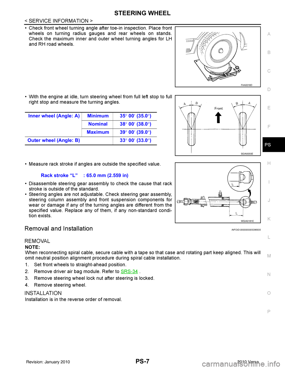
• Check front wheel turning angle after toe-in inspection. Place front wheels on turning radius gauges and rear wheels on stands.
Check the maximum inner and outer wheel turning angles for LH
and RH road wheels.
• With the engine at idle, turn steering wheel from full left stop to full right stop and measure the turning angles.
• Measure rack stroke if angles are outside the specified value.
• Disassemble steering gear assembly to check the cause that rack stroke is outside of the standard.
• Steering angles are not adjustable. Check steering gear assembly, steering column assembly and front suspension components for
wear or damage if any of the turning angles are different from the
specified value. Replace any of them, if any non-standard condi-
tion exists.
Removal and InstallationINFOID:0000000005396935
REMOVAL
NOTE:
When reconnecting spiral cable, secure cable with a tape so that case and rotating part keep aligned. This will
omit neutral position alignment procedure during spiral cable installation.
1. Set front wheels to straight-ahead position.
2. Remove driver air bag module. Refer to SRS-34
.
3. Remove steering wheel lock nut after steering is locked.
4. Remove steering wheel.
INSTALLATION
Installation is in the reverse order of removal.
FAA0016D
Inner wheel (Angle: A) Minimum 35 ° 00 ′ (35.0 °)
Nominal 38° 00′ (38.0 °)
Maximum 39 ° 00 ′ (39.0 °)
Outer wheel (Angle: B) 33° 00 ′ (33.0 °)
SGIA0055E
Rack stroke “L” : 65.0 mm (2.559 in)
WGIA0181E
Revision: January 20102010 Versa
Page 3470 of 3745
PS-12
< SERVICE INFORMATION >
POWER STEERING GEAR
POWER STEERING GEAR
Removal and InstallationINFOID:0000000005396937
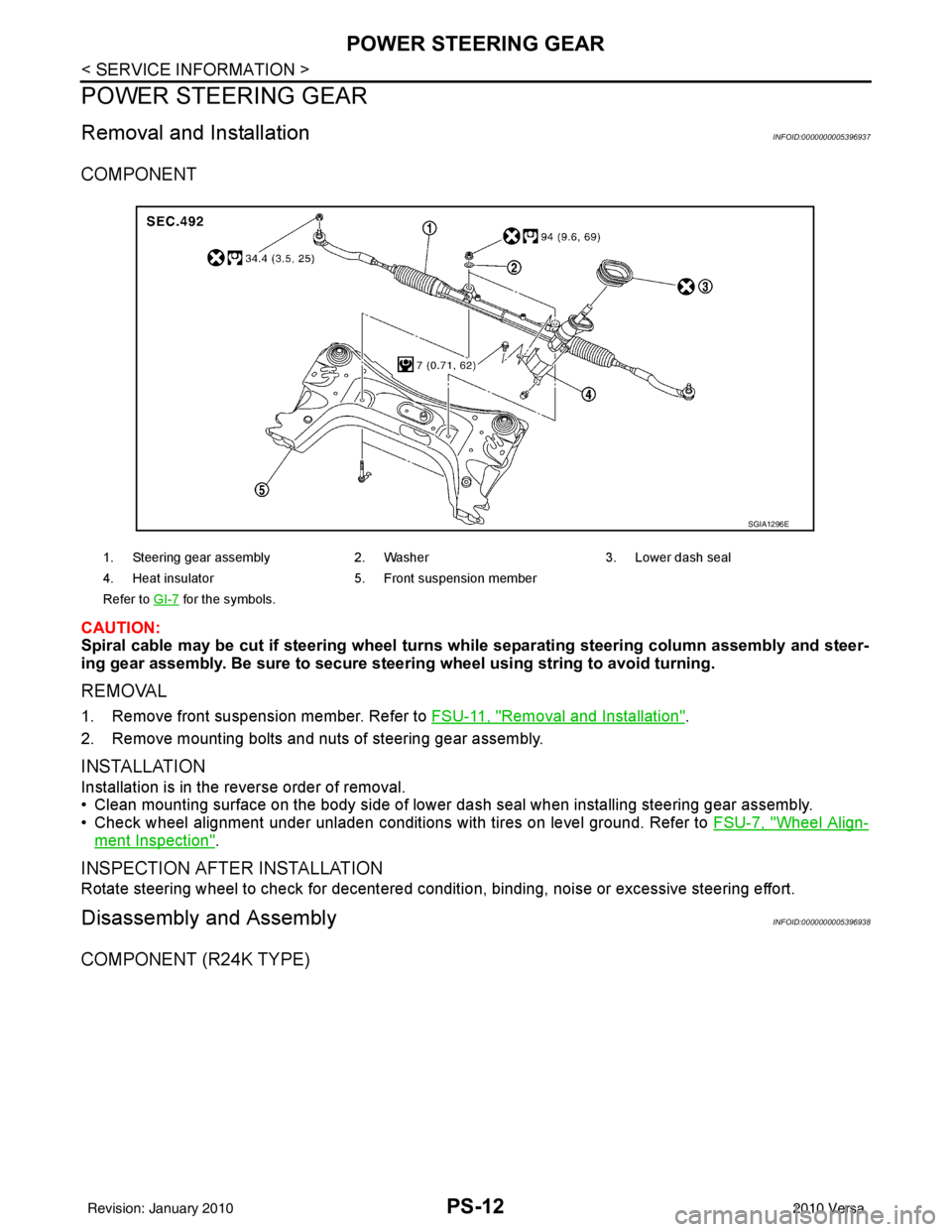
COMPONENT
CAUTION:
Spiral cable may be cut if steering wheel turns while separating steering column assembly and steer-
ing gear assembly. Be sure to secure steer ing wheel using string to avoid turning.
REMOVAL
1. Remove front suspension member. Refer to FSU-11, "Removal and Installation".
2. Remove mounting bolts and nuts of steering gear assembly.
INSTALLATION
Installation is in the reverse order of removal.
• Clean mounting surface on the body side of lower dash seal when installing steering gear assembly.
• Check wheel alignment under unladen conditions with tires on level ground. Refer to FSU-7, "
Wheel Align-
ment Inspection".
INSPECTION AFTER INSTALLATION
Rotate steering wheel to check for decentered condition, binding, noise or excessive steering effort.
Disassembly and AssemblyINFOID:0000000005396938
COMPONENT (R24K TYPE)
1. Steering gear assembly2. Washer 3. Lower dash seal
4. Heat insulator 5. Front suspension member
Refer to GI-7
for the symbols.
SGIA1296E
Revision: January 20102010 Versa