2010 NISSAN LATIO sensor
[x] Cancel search: sensorPage 1229 of 3745
COMBINATION METERSDI-19
< SERVICE INFORMATION >
C
DE
F
G H
I
J
L
M A
B
DI
N
O P
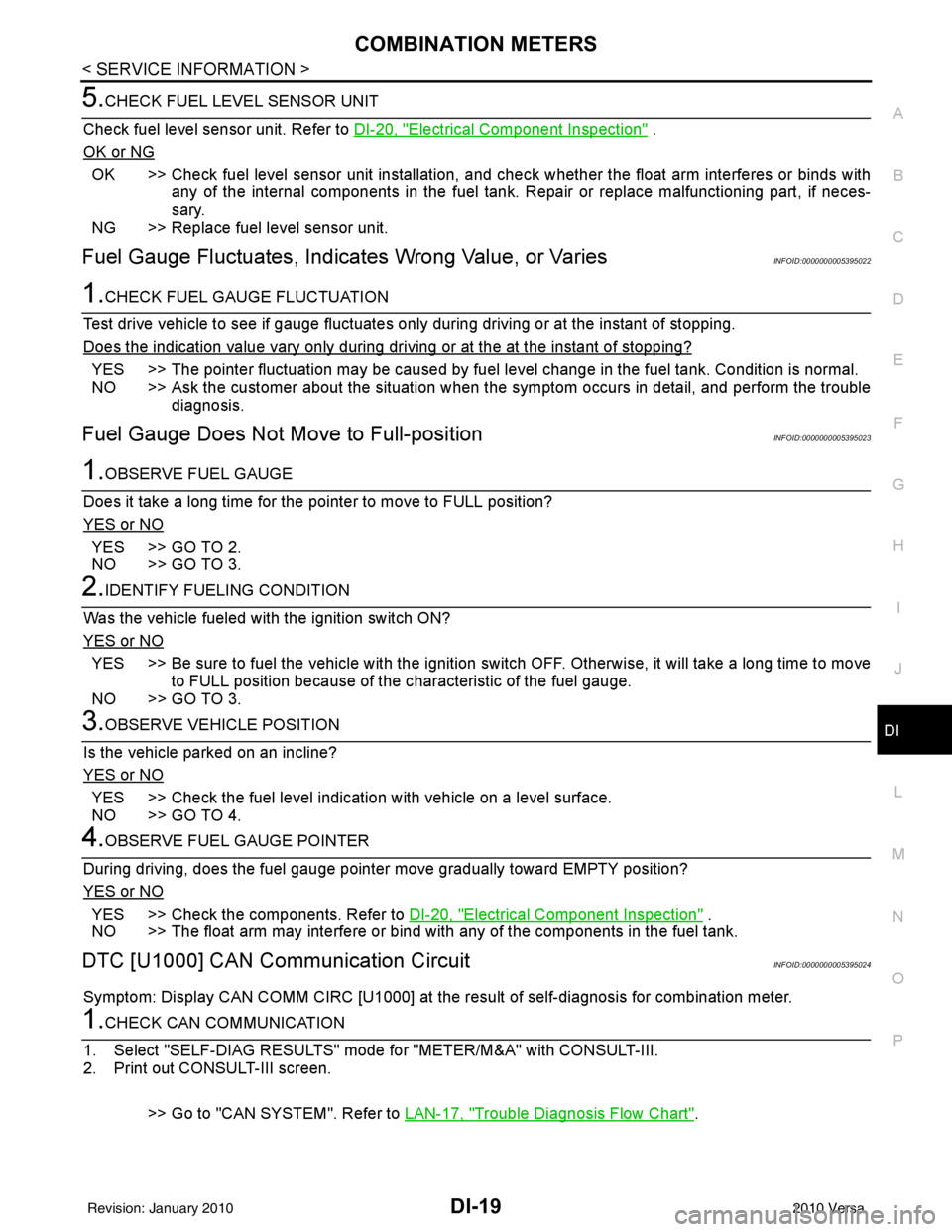
5.CHECK FUEL LEVEL SENSOR UNIT
Check fuel level sensor unit. Refer to DI-20, "
Electrical Component Inspection" .
OK or NG
OK >> Check fuel level sensor unit installation, and c heck whether the float arm interferes or binds with
any of the internal components in the fuel tank. Repair or replace malfunctioning part, if neces-
sary.
NG >> Replace fuel level sensor unit.
Fuel Gauge Fluctuates, Indica tes Wrong Value, or VariesINFOID:0000000005395022
1.CHECK FUEL GAUGE FLUCTUATION
Test drive vehicle to see if gauge fluctuates onl y during driving or at the instant of stopping.
Does the indication value vary only during dr iving or at the at the instant of stopping?
YES >> The pointer fluctuation may be caused by fuel level change in the fuel tank. Condition is normal.
NO >> Ask the customer about the situation when the symptom occurs in detail, and perform the trouble diagnosis.
Fuel Gauge Does Not Move to Full-positionINFOID:0000000005395023
1.OBSERVE FUEL GAUGE
Does it take a long time for the pointer to move to FULL position?
YES or NO
YES >> GO TO 2.
NO >> GO TO 3.
2.IDENTIFY FUELING CONDITION
Was the vehicle fueled with the ignition switch ON?
YES or NO
YES >> Be sure to fuel the vehicle with the ignition swit ch OFF. Otherwise, it will take a long time to move
to FULL position because of the c haracteristic of the fuel gauge.
NO >> GO TO 3.
3.OBSERVE VEHICLE POSITION
Is the vehicle parked on an incline?
YES or NO
YES >> Check the fuel level indicati on with vehicle on a level surface.
NO >> GO TO 4.
4.OBSERVE FUEL GAUGE POINTER
During driving, does the fuel gauge pointer move gradually toward EMPTY position?
YES or NO
YES >> Check the components. Refer to DI-20, "Electrical Component Inspection" .
NO >> The float arm may interfere or bind with any of the components in the fuel tank.
DTC [U1000] CAN Communication CircuitINFOID:0000000005395024
Symptom: Display CAN COMM CIRC [U1000] at the re sult of self-diagnosis for combination meter.
1.CHECK CAN COMMUNICATION
1. Select "SELF-DIAG RESULTS" mode for "METER/M&A" with CONSULT-III.
2. Print out CONSULT-III screen.
>> Go to "CAN SYSTEM". Refer to LAN-17, "
Trouble Diagnosis Flow Chart".
Revision: January 20102010 Versa
Page 1230 of 3745
DI-20
< SERVICE INFORMATION >
COMBINATION METERS
Electrical Component Inspection
INFOID:0000000005395025
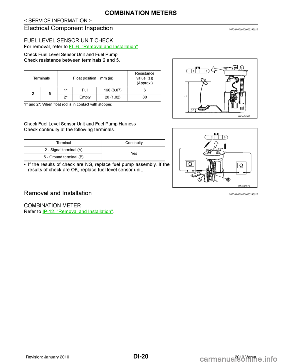
FUEL LEVEL SENSOR UNIT CHECK
For removal, refer to FL-6, "Removal and Installation" .
Check Fuel Level Sensor Unit and Fuel Pump
Check resistance between terminals 2 and 5.
1* and 2*: When float rod is in contact with stopper.
Check Fuel Level Sensor Unit and Fuel Pump Harness
Check continuity at the following terminals.
• If the results of check are NG, replace fuel pump assembly. If the
results of check are OK, replace fuel level sensor unit.
Removal and InstallationINFOID:0000000005395026
COMBINATION METER
Refer to IP-12, "Removal and Installation".
Terminals Float position mm (in) Resistance
value ( Ω)
(Approx.)
25 1* Full 160 (8.07)
6
2* Empty 20 (1.02) 80
WKIA5456E
TerminalContinuity
2 - Signal terminal (A) Ye s
5 - Ground terminal (B)
WKIA5457E
Revision: January 20102010 Versa
Page 1255 of 3745
WARNING CHIMEDI-45
< SERVICE INFORMATION >
C
DE
F
G H
I
J
L
M A
B
DI
N
O P
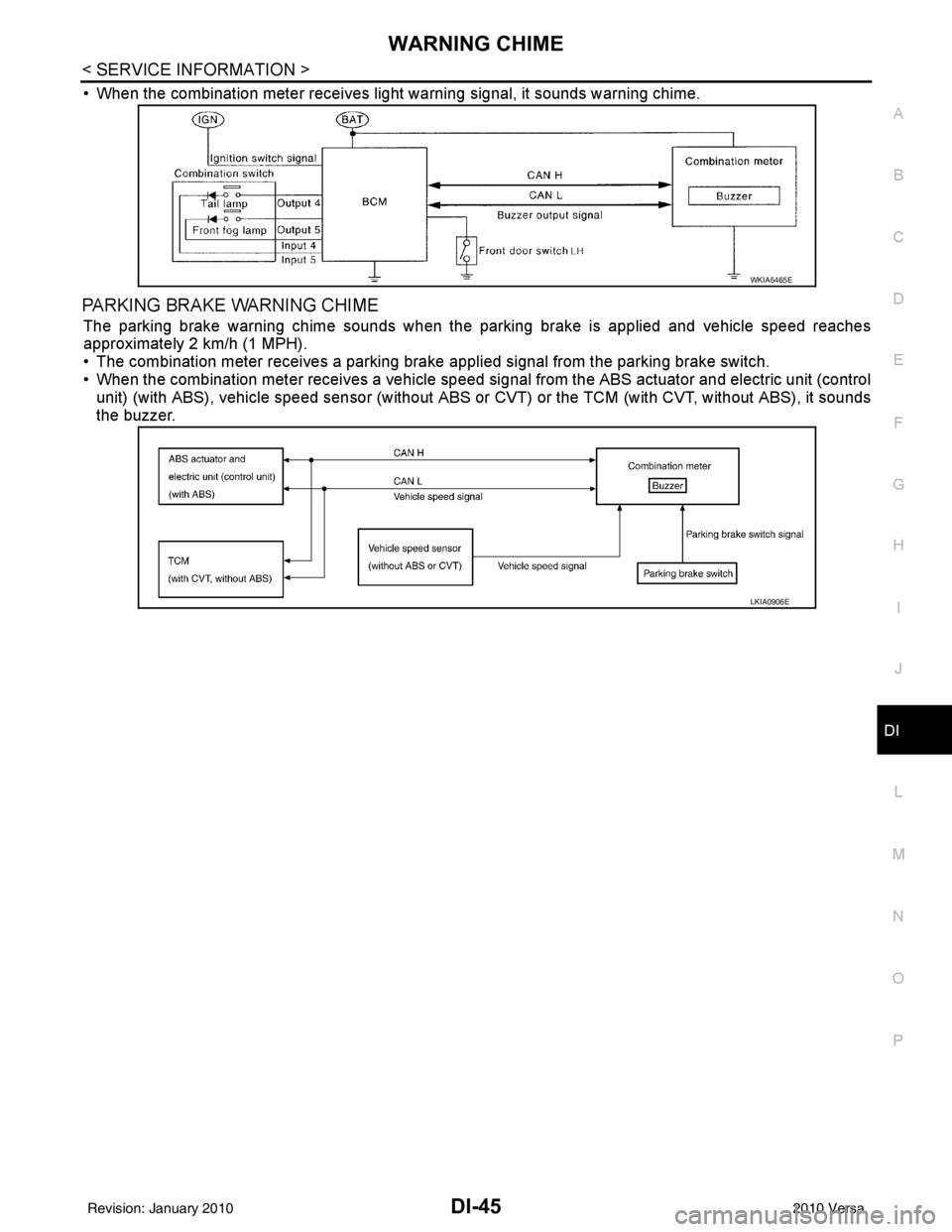
• When the combination meter receives light warning signal, it sounds warning chime.
PARKING BRAKE WARNING CHIME
The parking brake warning chime sounds when the parking brake is applied and vehicle speed reaches
approximately 2 km/h (1 MPH).
• The combination meter receives a parking brake applied signal from the parking brake switch.
• When the combination meter receives a vehicle speed si gnal from the ABS actuator and electric unit (control
unit) (with ABS), vehicle speed sensor (without ABS or CVT) or the TCM (with CVT, without ABS), it sounds
the buzzer.
WKIA5465E
LKIA0906E
Revision: January 20102010 Versa
Page 1267 of 3745

EC-2
CAN COMMUNICATION ...................................59
System Description .................................................59
COOLING FAN CONTROL ...............................60
System Diagram .................................................. ...60
System Description .................................................60
Component Parts Location ...................................62
Component Description ..........................................66
EVAPORATIVE EMISSION SYSTEM ...............68
System Diagram .................................................. ...68
System Description .................................................68
Component Parts Location ...................................72
Component Description .........................................76
INTAKE VALVE TIMING CONTROL .................78
System Diagram .................................................. ...78
System Description .................................................78
Component Parts Location ...................................79
Component Description ..........................................83
ON BOARD DIAGNOSTIC (OBD) SYSTEM .....84
Diagnosis Description .......................................... ...84
CONSULT-III Function ...........................................98
Diagnosis Tool Function ......................................104
COMPONENT DIAGNOSIS .......................106
TROUBLE DIAGNOSIS - SPECIFICATION
VALUE ............................................................ .
106
Description ........................................................... ..106
Component Function Check ..................................106
Diagnosis Procedure .............................................107
TROUBLE DIAGNOSIS FOR INTERMITTENT
INCIDENT ........................................................
114
Description ........................................................... ..114
Diagnosis Procedure .............................................114
POWER SUPPLY AND GROUND CIRCUIT ...115
Wiring Diagram .................................................... ..115
Diagnosis Procedure .............................................115
Ground Inspection .................................................119
U0101 CAN COMM CIRCUIT ..........................120
Description ........................................................... ..120
DTC Logic ..............................................................120
Wiring Diagram ......................................................121
Diagnosis Procedure .............................................121
U0140 CAN COMM CIRCUIT ..........................122
Description ........................................................... ..122
DTC Logic ..............................................................122
Wiring Diagram ......................................................123
Diagnosis Procedure .............................................123
U1001 CAN COMM CIRCUIT ..........................124
Description ........................................................... ..124
DTC Logic ..............................................................124
Wiring Diagram ......................................................125
Diagnosis Procedure .............................................125
P0011 IVT CONTROL ......................................126
DTC Logic ............................................................ .126
Diagnosis Procedure .............................................127
Component Inspection ..........................................128
P0031, P0032 A/F SENSOR 1 HEATER ..........130
Description ........................................................... .130
DTC Logic .............................................................130
Wiring Diagram .....................................................131
Diagnosis Procedure .............................................131
Component Inspection ..........................................133
P0037, P0038 HO2S2 HEATER .......................134
Description ........................................................... .134
DTC Logic .............................................................134
Wiring Diagram .....................................................135
Diagnosis Procedure .............................................135
Component Inspection ..........................................137
P0075 IVT CONTROL SOLENOID VALVE ......138
Description ........................................................... .138
DTC Logic .............................................................138
Wiring Diagram .....................................................139
Diagnosis Procedure .............................................139
Component Inspection ..........................................140
P0101 MAF SENSOR .......................................142
Description ........................................................... .142
DTC Logic .............................................................142
Component Function Check .................................143
Wiring Diagram .....................................................145
Diagnosis Procedure .............................................145
Component Inspection ..........................................147
P0102, P0103 MAF SENSOR ..........................150
Description ........................................................... .150
DTC Logic .............................................................150
Wiring Diagram .....................................................151
Diagnosis Procedure .............................................151
Component Inspection ..........................................153
P0112, P0113 IAT SENSOR ............................156
Description ............................................................156
DTC Logic .............................................................156
Wiring Diagram .....................................................157
Diagnosis Procedure .............................................157
Component Inspection ..........................................158
P0116 ECT SENSOR .......................................159
Description ............................................................159
DTC Logic .............................................................159
Diagnosis Procedure .............................................160
Component Inspection ..........................................160
P0117, P0118 ECT SENSOR ...........................161
Description ............................................................161
DTC Logic .............................................................161
Wiring Diagram .....................................................162
Diagnosis Procedure .............................................162
Component Inspection ..........................................163
Revision: January 20102010 Versa
Page 1268 of 3745
EC-3
C
DE
F
G H
I
J
K L
M
EC A
N
O P
P0122, P0123 TP SENSOR ........................... ..165
Description .......................................................... ..165
DTC Logic .............................................................165
Wiring Diagram .....................................................166
Diagnosis Procedure .............................................166
Component Inspection ..........................................168
Special Repair Requirement .................................168
P0125 ECT SENSOR ..................................... ..169
Description .......................................................... ..169
DTC Logic .............................................................169
Diagnosis Procedure .............................................170
Component Inspection ..........................................170
P0127 IAT SENSOR .........................................172
Description .......................................................... ..172
DTC Logic .............................................................172
Diagnosis Procedure .............................................173
Component Inspection ..........................................173
P0128 THERMOSTAT FUNCTION ..................174
DTC Logic ........................................................... ..174
Diagnosis Procedure .............................................174
Component Inspection ..........................................175
P0130 A/F SENSOR 1 ......................................176
Description ............................................................176
DTC Logic .............................................................176
Component Function Check ..................................177
Wiring Diagram .....................................................179
Diagnosis Procedure .............................................179
P0131 A/F SENSOR 1 ......................................182
Description ............................................................182
DTC Logic .............................................................182
Wiring Diagram .....................................................184
Diagnosis Procedure .............................................184
P0132 A/F SENSOR 1 ......................................187
Description ............................................................187
DTC Logic .............................................................187
Wiring Diagram .....................................................189
Diagnosis Procedure .............................................189
P0133 A/F SENSOR 1 ......................................192
Description ............................................................192
DTC Logic .............................................................192
Wiring Diagram .....................................................194
Diagnosis Procedure .............................................195
P0137 HO2S2 ...................................................198
Description .......................................................... ..198
DTC Logic .............................................................198
Component Function Check ..................................199
Wiring Diagram .....................................................201
Diagnosis Procedure .............................................201
Component Inspection ..........................................203
P0138 HO2S2 ...................................................206
Description .......................................................... ..206
DTC Logic .............................................................206
Component Function Check ................................ ..207
Wiring Diagram ......................................................209
Diagnosis Procedure .............................................209
Component Inspection ...........................................212
P0139 HO2S2 ..................................................215
Description .............................................................215
DTC Logic ..............................................................215
Component Function Check ..................................216
Wiring Diagram ......................................................218
Diagnosis Procedure .............................................218
Component Inspection ...........................................220
P0171 FUEL INJECTION SYSTEM FUNC-
TION ................................................................
223
DTC Logic ..............................................................223
Wiring Diagram ......................................................225
Diagnosis Procedure .............................................225
P0172 FUEL INJECTION SYSTEM FUNC-
TION ................................................................
229
DTC Logic ..............................................................229
Wiring Diagram ......................................................231
Diagnosis Procedure .............................................231
P0181 FTT SENSOR .......................................234
Description .............................................................234
DTC Logic ..............................................................234
Wiring Diagram ......................................................236
Diagnosis Procedure .............................................236
Component Inspection ...........................................238
P0182, P0183 FTT SENSOR ..........................239
Description .............................................................239
DTC Logic ..............................................................239
Wiring Diagram ......................................................240
Diagnosis Procedure .............................................240
Component Inspection ...........................................242
P0222, P0223 TP SENSOR ............................243
Description .............................................................243
DTC Logic ..............................................................243
Wiring Diagram ......................................................244
Diagnosis Procedure .............................................244
Component Inspection ...........................................246
Special Repair Requirement ..................................246
P0300, P0301, P0302, P0303, P0304 MIS-
FIRE .................................................................
247
DTC Logic ..............................................................247
Diagnosis Procedure .............................................248
P0327, P0328 KS ............................................253
Description .............................................................253
DTC Logic ..............................................................253
Wiring Diagram ......................................................254
Diagnosis Procedure .............................................254
Component Inspection ...........................................255
P0335 CKP SENSOR (POS) ...........................257
Description .............................................................257
Revision: January 20102010 Versa
Page 1269 of 3745

EC-4
DTC Logic ..............................................................257
Wiring Diagram ......................................................258
Diagnosis Procedure .............................................259
Component Inspection ...........................................261
P0340 CMP SENSOR (PHASE) ......................262
Description ........................................................... ..262
DTC Logic ..............................................................262
Wiring Diagram ......................................................264
Diagnosis Procedure .............................................264
Component Inspection ...........................................266
P0420 THREE WAY CATALYST FUNCTION .267
DTC Logic ..............................................................267
Component Function Check ..................................268
Diagnosis Procedure .............................................269
P0441 EVAP CONTROL SYSTEM ..................272
DTC Logic ............................................................ ..272
Component Function Check ..................................273
Diagnosis Procedure .............................................274
Component Inspection (Drain filter) .......................277
P0442 EVAP CONTROL SYSTEM ..................278
DTC Logic ............................................................ ..278
Diagnosis Procedure .............................................279
Component Inspection (Fuel filler cap) ..................283
Component Inspection (Drain filter) .......................283
P0443 EVAP CANISTER PURGE VOLUME
CONTROL SOLENOID VALVE .......................
285
Description ........................................................... ..285
DTC Logic ..............................................................285
Wiring Diagram ......................................................287
Diagnosis Procedure .............................................287
Component Inspection ...........................................290
P0444, P0445 EVAP CANISTER PURGE
VOLUME CONTROL SOLENOID VALVE ......
291
Description ........................................................... ..291
DTC Logic ..............................................................291
Wiring Diagram ......................................................292
Diagnosis Procedure .............................................292
Component Inspection ...........................................294
P0447 EVAP CANISTER VENT CONTROL
VALVE .............................................................
295
Description ........................................................... ..295
DTC Logic ..............................................................295
Wiring Diagram ......................................................296
Diagnosis Procedure .............................................296
Component Inspection ...........................................298
P0448 EVAP CANISTER VENT CONTROL
VALVE .............................................................
300
Description ........................................................... ..300
DTC Logic ..............................................................300
Wiring Diagram ......................................................302
Diagnosis Procedure .............................................302
Component Inspection ...........................................304
P0451 EVAP CONTROL SYSTEM PRES-
SURE SENSOR ................................................
306
Description ........................................................... .306
DTC Logic .............................................................306
Diagnosis Procedure .............................................306
Component Inspection ..........................................308
P0452 EVAP CONTROL SYSTEM PRES-
SURE SENSOR ................................................
309
Description ........................................................... .309
DTC Logic .............................................................309
Wiring Diagram .....................................................311
Diagnosis Procedure .............................................311
Component Inspection ..........................................314
P0453 EVAP CONTROL SYSTEM PRES-
SURE SENSOR ................................................
316
Description ........................................................... .316
DTC Logic .............................................................316
Wiring Diagram .....................................................318
Diagnosis Procedure .............................................318
Component Inspection ..........................................322
P0455 EVAP CONTROL SYSTEM ..................323
DTC Logic .............................................................323
Diagnosis Procedure .............................................324
Component Inspection (Fuel filler cap) .................327
Component Inspection (Drain filter) ......................328
P0456 EVAP CONTROL SYSTEM ..................329
DTC Logic .............................................................329
Component Function Check .................................331
Diagnosis Procedure .............................................331
Component Inspection (Fuel filler cap) .................334
Component Inspection (Drain filter) ......................335
P0460 FUEL LEVEL SENSOR .........................336
Description ........................................................... .336
DTC Logic .............................................................336
Diagnosis Procedure .............................................336
P0461 FUEL LEVEL SENSOR .........................337
Description ........................................................... .337
DTC Logic .............................................................337
Component Function Check .................................337
Diagnosis Procedure .............................................338
P0462, P0463 FUEL LEVEL SENSOR ............339
Description ........................................................... .339
DTC Logic .............................................................339
Diagnosis Procedure .............................................339
P0500 VSS ........................................................341
Description ........................................................... .341
DTC Logic .............................................................341
Component Function Check .................................342
Diagnosis Procedure .............................................342
P0506 ISC SYSTEM .........................................343
Description ........................................................... .343
DTC Logic .............................................................343
Revision: January 20102010 Versa
Page 1270 of 3745
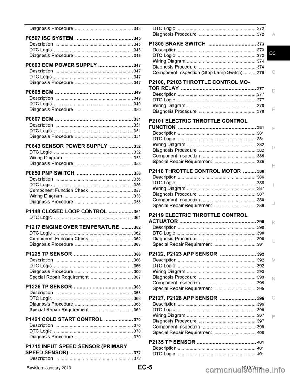
EC-5
C
DE
F
G H
I
J
K L
M
EC A
N
O P
Diagnosis Procedure ...........................................
..
343
P0507 ISC SYSTEM .........................................345
Description .......................................................... ..345
DTC Logic .............................................................345
Diagnosis Procedure .............................................345
P0603 ECM POWER SUPPLY .........................347
Description .......................................................... ..347
DTC Logic .............................................................347
Diagnosis Procedure .............................................347
P0605 ECM .......................................................349
Description ............................................................349
DTC Logic .............................................................349
Diagnosis Procedure .............................................350
P0607 ECM .......................................................351
Description ............................................................351
DTC Logic .............................................................351
Diagnosis Procedure .............................................351
P0643 SENSOR POWER SUPPLY .................352
DTC Logic ........................................................... ..352
Wiring Diagram .....................................................353
Diagnosis Procedure .............................................353
P0850 PNP SWITCH ........................................356
Description ............................................................356
DTC Logic .............................................................356
Component Function Check ..................................357
Wiring Diagram .....................................................358
Diagnosis Procedure .............................................358
P1148 CLOSED LOOP CONTROL ..................361
DTC Logic .............................................................361
P1217 ENGINE OVER TEMPERATURE .........362
DTC Logic ........................................................... ..362
Component Function Check ..................................362
Diagnosis Procedure .............................................363
P1225 TP SENSOR ..........................................366
Description .......................................................... ..366
DTC Logic .............................................................366
Diagnosis Procedure .............................................366
Special Repair Requirement .................................367
P1226 TP SENSOR ........................................ ..368
Description .......................................................... ..368
DTC Logic .............................................................368
Diagnosis Procedure .............................................368
Special Repair Requirement .................................369
P1421 COLD START CONTROL ................... ..370
Description .......................................................... ..370
DTC Logic .............................................................370
Diagnosis Procedure .............................................370
P1715 INPUT SPEED SENSOR (PRIMARY
SPEED SENSOR) .......................................... ..
372
Description .......................................................... ..372
DTC Logic ............................................................ ..372
Diagnosis Procedure .............................................372
P1805 BRAKE SWITCH .................................373
Description .............................................................373
DTC Logic ..............................................................373
Wiring Diagram ......................................................374
Diagnosis Procedure .............................................374
Component Inspection (Stop Lamp Switch) ..........376
P2100, P2103 THROTTLE CONTROL MO-
TOR RELAY ....................................................
377
Description .............................................................377
DTC Logic ..............................................................377
Wiring Diagram ......................................................378
Diagnosis Procedure .............................................378
P2101 ELECTRIC THROTTLE CONTROL
FUNCTION ......................................................
381
Description ........................................................... ..381
DTC Logic ..............................................................381
Wiring Diagram ......................................................382
Diagnosis Procedure .............................................382
Component Inspection ...........................................385
Special Repair Requirement ..................................385
P2118 THROTTLE CONTROL MOTOR .........386
Description .............................................................386
DTC Logic ..............................................................386
Wiring Diagram ......................................................387
Diagnosis Procedure .............................................387
Component Inspection ...........................................388
Special Repair Requirement ..................................389
P2119 ELECTRIC THROTTLE CONTROL
ACTUATOR .....................................................
390
Description .............................................................390
DTC Logic ..............................................................390
Diagnosis Procedure .............................................390
Special Repair Requirement ..................................391
P2122, P2123 APP SENSOR .........................392
Description .............................................................392
DTC Logic ..............................................................392
Wiring Diagram ......................................................393
Diagnosis Procedure .............................................393
Component Inspection ...........................................395
Special Repair Requirement ..................................395
P2127, P2128 APP SENSOR .........................396
Description .............................................................396
DTC Logic ..............................................................396
Wiring Diagram ......................................................397
Diagnosis Procedure .............................................397
Component Inspection ...........................................399
Special Repair Requirement ..................................400
P2135 TP SENSOR .........................................401
Description .............................................................401
DTC Logic ..............................................................401
Revision: January 20102010 Versa
Page 1271 of 3745

EC-6
Wiring Diagram ......................................................402
Diagnosis Procedure .............................................402
Component Inspection ...........................................404
Special Repair Requirement ..................................404
P2138 APP SENSOR ..................................... .405
Description ........................................................... ..405
DTC Logic ..............................................................405
Wiring Diagram ......................................................406
Diagnosis Procedure .............................................406
Component Inspection ...........................................409
Special Repair Requirement ..................................409
P2A00 A/F SENSOR 1 ................................... .410
Description ........................................................... ..410
DTC Logic ..............................................................410
Wiring Diagram ......................................................411
Diagnosis Procedure .............................................412
COOLING FAN ................................................415
Description ........................................................... ..415
Component Function Check ..................................415
Wiring Diagram ......................................................416
Diagnosis Procedure .............................................417
Component Inspection ...........................................419
ELECTRICAL LOAD SIGNAL .........................421
Description ........................................................... ..421
Component Function Check ..................................421
Diagnosis Procedure .............................................421
FUEL INJECTOR .............................................423
Description ........................................................... ..423
Component Function Check ..................................423
Wiring Diagram ......................................................424
Diagnosis Procedure .............................................424
Component Inspection ...........................................425
FUEL PUMP .....................................................427
Description ........................................................... ..427
Component Function Check ..................................427
Wiring Diagram ......................................................428
Diagnosis Procedure .............................................428
Component Inspection ...........................................430
IGNITION SIGNAL ...........................................432
Description ........................................................... ..432
Component Function Check ..................................432
Wiring Diagram ......................................................433
Diagnosis Procedure .............................................434
Component Inspection (Ignition Coil with Power
Transistor) .............................................................
437
Component Inspection (Condenser-2) ..................438
MALFUNCTION INDICATOR LAMP ...............439
Description ........................................................... ..439
Component Function Check ..................................439
Wiring Diagram ......................................................440
Diagnosis Procedure .............................................441
ON BOARD REFUELING VAPOR RECOV-
ERY (ORVR) .....................................................
443
Description ........................................................... .443
Component Function Check .................................443
Diagnosis Procedure .............................................443
Component Inspection (Refueling EVAP vapor cut
valve) ................................................................... .
446
Component Inspection (Drain filter) ......................448
POSITIVE CRANKCASE VENTILATION .........449
Description ........................................................... .449
Component Inspection ..........................................449
REFRIGERANT PRESSURE SENSOR ...........450
Description ........................................................... .450
Component Function Check .................................450
Wiring Diagram .....................................................451
Diagnosis Procedure .............................................451
ECU DIAGNOSIS ......................................454
ECM ................................................................ ..454
Reference Value .................................................. .454
Wiring Diagram — ENGINE CONTROL SYSTEM
— ..........................................................................
464
Fail Safe ...............................................................465
DTC Inspection Priority Chart .............................467
DTC Index ............................................................468
How to Set SRT Code .......................................471
How to Erase Permanent DTC .............................473
Test Value and Test Limit .....................................477
SYMPTOM DIAGNOSIS ...........................484
ENGINE CONTROL SYSTEM SYMPTOMS .. ..484
Symptom Table .................................................... .484
NORMAL OPERATING CONDITION ...............488
Description ........................................................... .488
PRECAUTION ...........................................489
PRECAUTIONS .............................................. ..489
Precaution for Supplemental Restraint System
(SRS) "AIR BAG" and "SEAT BELT PRE-TEN-
SIONER" .............................................................. .
489
Precaution Necessary for Steering Wheel Rota-
tion After Battery Disconnect ................................
489
Precaution for Procedure without Cowl Top Cover .490
On Board Diagnosis (OBD) System of Engine and
A/T ........................................................................
490
General Precautions .............................................490
PREPARATION .........................................494
PREPARATION .............................................. ..494
Special Service Tools .......................................... .494
Commercial Service Tools ....................................494
ON-VEHICLE MAINTENANCE .................496
Revision: January 20102010 Versa