2010 NISSAN LATIO wheel bolts
[x] Cancel search: wheel boltsPage 2563 of 3745
![NISSAN LATIO 2010 Service Repair Manual EM-204
< SERVICE INFORMATION >[MR18DE]
CYLINDER BLOCK
26. Install flywheel (M/T models) or drive plate (1) (A/T or CVT mod-
els).
• Secure crankshaft using Tool (A), and tighten bolts crosswiseover NISSAN LATIO 2010 Service Repair Manual EM-204
< SERVICE INFORMATION >[MR18DE]
CYLINDER BLOCK
26. Install flywheel (M/T models) or drive plate (1) (A/T or CVT mod-
els).
• Secure crankshaft using Tool (A), and tighten bolts crosswiseover](/manual-img/5/57358/w960_57358-2562.png)
EM-204
< SERVICE INFORMATION >[MR18DE]
CYLINDER BLOCK
26. Install flywheel (M/T models) or drive plate (1) (A/T or CVT mod-
els).
• Secure crankshaft using Tool (A), and tighten bolts crosswiseover several times.
NOTE:
A/T model shown CVT and M/T similar.
• Install pilot converter (3), drive plate (1) and reinforcement plate (2) as shown (A/T or CVT models).
• Using a suitable tool of 33 mm (1.30 in) in diameter, press-fit pilot converter into the end of crankshaft until it stops (A/T or
CVT models).
NOTE:
M/T models have no pilot converter and reinforcement plate.
27. Install knock sensor (1) with connector facing toward the rear of engine.
CAUTION:
• Never tighten bolts while holding the connector.
• If any impact by dropping is applied to knock sensor,replace it with a new one.
NOTE:
• Make sure that there is no foreign material on the cylinder
block mating surface and the back surface of knock sensor.
• Make sure that knock sensor does not interfere with other parts.
28. Install crankshaft position sensor (POS) and crankshaft position sensor (POS) cover. CAUTION:
• Avoid impacts such as a dropping.
• Keep it away from metal particles.
• Never place sensor in a location where it is exposed to magnetism.
29. Install oil filter (for intake valv e timing control) (1) in the direction
shown.
• Make sure that the oil filter does not protrude from the upper surface of cylinder block (2) after installation.
30. Assembly is in the reverse order of disassembly. Tool number : KV11105210 (J-44716)
PBIC3998E
A : Crankshaft rear end
B : Rounded
C : Chamfered
PBIC3259J
A : Cylinder block left side
: Engine front
PBIC3246J
PBIC3260J
Revision: January 20102010 Versa
Page 2609 of 3745
FAX-4
< SERVICE INFORMATION >
PREPARATION
PREPARATION
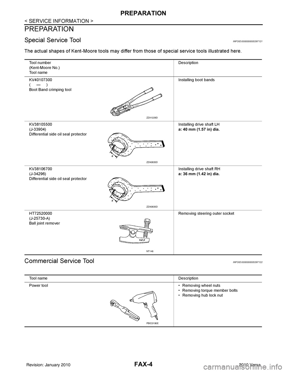
Special Service ToolINFOID:0000000005397121
The actual shapes of Kent-Moore tools may differ from those of special service tools illustrated here.
Commercial Service ToolINFOID:0000000005397122
Tool number
(Kent-Moore No.)
Tool name Description
KV40107300
(—)
Boot Band crimping tool Installing boot bands
KV38105500
(J-33904)
Differential side oil seal protector Installing drive shaft LH
a: 40 mm (1.57 in) dia.
KV38106700
(J-34296)
Differential side oil seal protector Installing drive shaft RH
a: 36 mm (1.42 in) dia.
HT72520000
(J-25730-A)
Ball joint remover Removing steering outer socket
ZZA1229D
ZZA0835D
ZZA0835D
NT146
Tool name
Description
Power tool • Removing wheel nuts
• Removing torque member bolts
• Removing hub lock nut
PBIC0190E
Revision: January 20102010 Versa
Page 2612 of 3745
FRONT WHEEL HUB AND KNUCKLEFAX-7
< SERVICE INFORMATION >
CEF
G H
I
J
K L
M A
B
FA X
N
O P
2. Without disassembling the hydraulic lines, remove the torque member bolts using power tool. Then repo- sition the torque member and brake caliper assembly aside with wire. Refer to BR-25
.
CAUTION:
Do not depress brake pedal while brake caliper is removed.
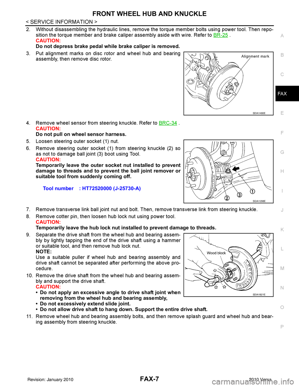
3. Put alignment marks on disc rotor and wheel hub and bearing assembly, then remove disc rotor.
4. Remove wheel sensor from steering knuckle. Refer to BRC-34
.
CAUTION:
Do not pull on wheel sensor harness.
5. Loosen steering outer socket (1) nut.
6. Remove steering outer socket (1) from steering knuckle (2) so as not to damage ball joint (3) boot using Tool.
CAUTION:
Temporarily leave the outer socket nut installed to prevent
damage to threads and to prevent the ball joint remover or
suitable tool from suddenly coming off.
7. Remove transverse link ball joint nut and bolt. Then, remove transverse link from steering knuckle.
8. Remove cotter pin, then loosen hub lock nut using power tool. CAUTION:
Temporarily leave the hub lock nut inst alled to prevent damage to threads.
9. Separate the drive shaft from the wheel hub and bearing assem- bly by lightly tapping the end of the drive shaft using a hammer
or suitable tool, and then remove hub lock nut.
NOTE:
Use a suitable puller if wheel hub and bearing assembly and
drive shaft cannot be separated after performing the above pro-
cedure.
10. Remove the drive shaft from the wheel hub and bearing assem- bly and support the drive shaft.
CAUTION:
• Do not apply an excessive angle to drive shaft joint when
removing from the wheel hub and bearing assembly,
• Do not excessively extend slide joint.
• Do not allow drive shaft to hang do wn. Support the entire drive shaft.
11. Remove wheel hub and bearing assembly bolts, and then remove splash guard and wheel hub and bear- ing assembly from steering knuckle.
SDIA1480E
Tool number : HT72520000 (J-25730-A)
SGIA1298E
SDIA1821E
Revision: January 20102010 Versa
Page 2613 of 3745
FAX-8
< SERVICE INFORMATION >
FRONT WHEEL HUB AND KNUCKLE
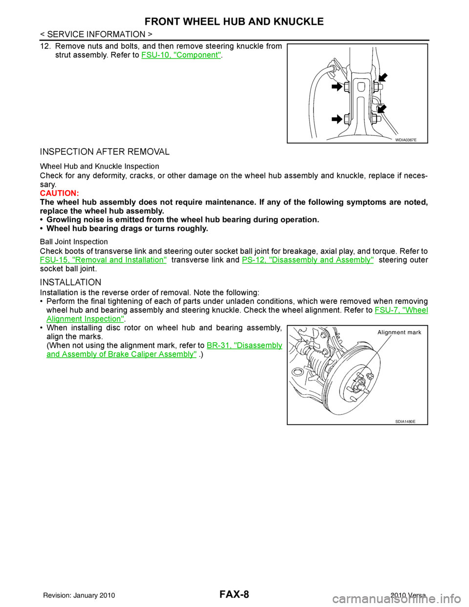
12. Remove nuts and bolts, and then remove steering knuckle fromstrut assembly. Refer to FSU-10, "
Component".
INSPECTION AFTER REMOVAL
Wheel Hub and Knuckle Inspection
Check for any deformity, cracks, or other damage on the wheel hub assembly and knuckle, replace if neces-
sary.
CAUTION:
The wheel hub assembly does not require maintenance. If any of the following symptoms are noted,
replace the wheel hub assembly.
• Growling noise is emitted from the wheel hub bearing during operation.
• Wheel hub bearing drags or turns roughly.
Ball Joint Inspection
Check boots of transverse link and steering outer socket ball joint for breakage, axial play, and torque. Refer to
FSU-15, "
Removal and Installation" transverse link and PS-12, "Disassembly and Assembly" steering outer
socket ball joint.
INSTALLATION
Installation is the reverse order of removal. Note the following:
• Perform the final tightening of each of parts under unladen conditions, which were removed when removing wheel hub and bearing assembly and steering knuckl e. Check the wheel alignment. Refer to FSU-7, "
Wheel
Alignment Inspection".
• When installing disc rotor on wheel hub and bearing assembly,
align the marks.
(When not using the alignment mark, refer to BR-31, "
Disassembly
and Assembly of Brake Caliper Assembly" .)
WDIA0367E
SDIA1480E
Revision: January 20102010 Versa
Page 2616 of 3745
FRONT DRIVE SHAFTFAX-11
< SERVICE INFORMATION >
CEF
G H
I
J
K L
M A
B
FA X
N
O P
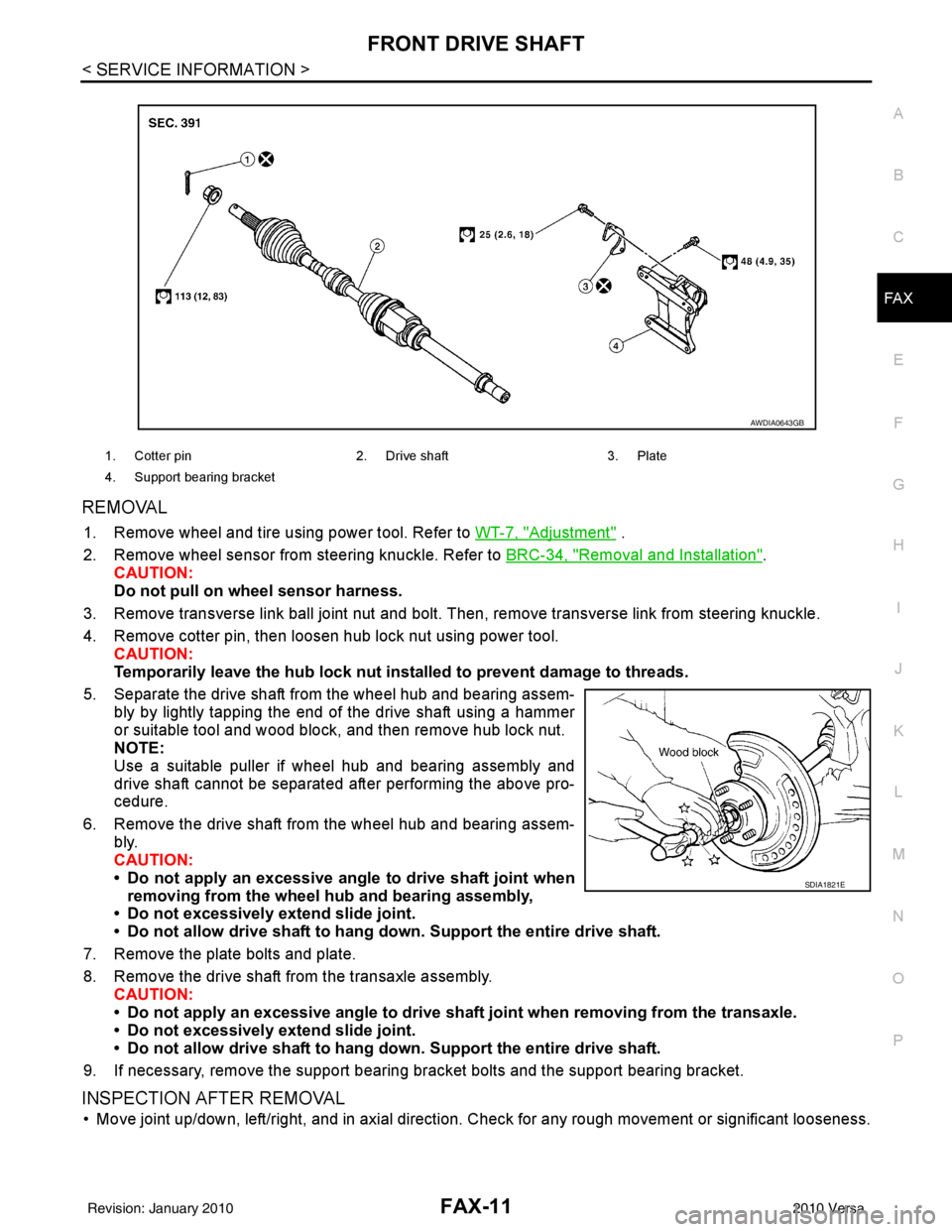
REMOVAL
1. Remove wheel and tire using power tool. Refer to WT-7, "Adjustment" .
2. Remove wheel sensor from steering knuckle. Refer to BRC-34, "
Removal and Installation".
CAUTION:
Do not pull on wheel sensor harness.
3. Remove transverse link ball joint nut and bolt. Then, remove transverse link from steering knuckle.
4. Remove cotter pin, then loosen hub lock nut using power tool. CAUTION:
Temporarily leave the hub lock nut inst alled to prevent damage to threads.
5. Separate the drive shaft from the wheel hub and bearing assem- bly by lightly tapping the end of the drive shaft using a hammer
or suitable tool and wood block, and then remove hub lock nut.
NOTE:
Use a suitable puller if wheel hub and bearing assembly and
drive shaft cannot be separated after performing the above pro-
cedure.
6. Remove the drive shaft from the wheel hub and bearing assem- bly.
CAUTION:
• Do not apply an excessive angle to drive shaft joint when
removing from the wheel hub and bearing assembly,
• Do not excessively extend slide joint.
• Do not allow drive shaft to hang do wn. Support the entire drive shaft.
7. Remove the plate bolts and plate.
8. Remove the drive shaft from the transaxle assembly. CAUTION:
• Do not apply an excessive angle to drive shaf t joint when removing from the transaxle.
• Do not excessively extend slide joint.
• Do not allow drive shaft to hang do wn. Support the entire drive shaft.
9. If necessary, remove the support bearing bracket bolts and the support bearing bracket.
INSPECTION AFTER REMOVAL
• Move joint up/down, left/right, and in axial direction. Check for any rough movement or significant looseness.
1. Cotter pin 2. Drive shaft 3. Plate
4. Support bearing bracket
AWDIA0643GB
SDIA1821E
Revision: January 20102010 Versa
Page 2655 of 3745
FSU-8
< SERVICE INFORMATION >
FRONT SUSPENSION ASSEMBLY
• This may result in an ERROR.
2. Some newer alignment machines are equipped with an optional “Rolling Compensation” method to “com- pensate” the sensors (alignment targets or head units). Do NOT use this “Rolling Compensation”
method.
• Use the “Jacking Compensation” method. After inst alling the alignment targets or head units, raise the
vehicle and rotate the wheels 1/2 turn both ways.
• See Instructions in the alignment machine you are using for more information.
CAMBER, CASTER AND KINGPIN INCLINATION ANGLES INSPECTION
• Camber, caster, kingpin inclination angles cannot be adjusted.
• Before inspection, mount front wheels onto turning radius gauge. Mount rear wheels onto a stand that has
same height so vehicle will remain horizontal.
Using a CCK Gauge
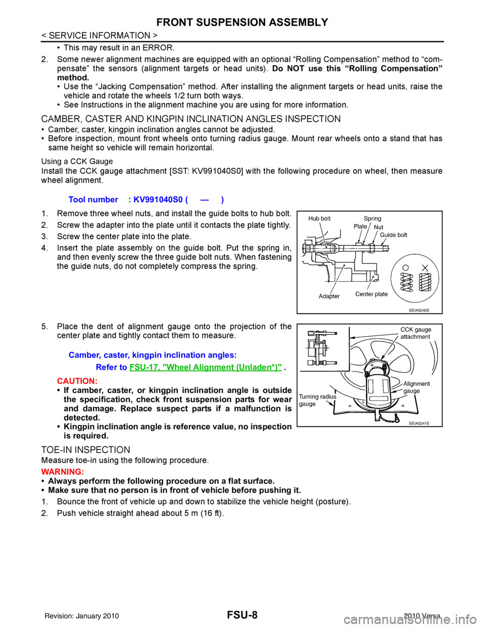
Install the CCK gauge attachment [SST: KV991040S0] with the following procedure on wheel, then measure
wheel alignment.
1. Remove three wheel nuts, and install the guide bolts to hub bolt.
2. Screw the adapter into the plate unt il it contacts the plate tightly.
3. Screw the center plate into the plate.
4. Insert the plate assembly on the guide bolt. Put the spring in, and then evenly screw the three guide bolt nuts. When fastening
the guide nuts, do not completely compress the spring.
5. Place the dent of alignment gauge onto the projection of the center plate and tightly contact them to measure.
CAUTION:
• If camber, caster, or kingpin inclination angle is outside
the specification, check front suspension parts for wear
and damage. Replace suspect parts if a malfunction is
detected.
• Kingpin inclination angle is reference value, no inspection
is required.
TOE-IN INSPECTION
Measure toe-in using the following procedure.
WARNING:
• Always perform the following procedure on a flat surface.
• Make sure that no person is in fr ont of vehicle before pushing it.
1. Bounce the front of vehicle up and down to stabilize the vehicle height (posture).
2. Push vehicle straight ahead about 5 m (16 ft). Tool number : KV991040S0 ( — )
SEIA0240E
Camber, caster, kingpi
n inclination angles:
Refer to FSU-17, "
Wheel Alignment (Unladen*)" .
SEIA0241E
Revision: January 20102010 Versa
Page 2658 of 3745
FRONT SUSPENSION ASSEMBLYFSU-11
< SERVICE INFORMATION >
C
DF
G H
I
J
K L
M A
B
FSU
N
O P
Removal and InstallationINFOID:0000000005397064
REMOVAL
1. Separate intermediate shaft from steering gear pinion shaft. Refer to PS-9, "Removal and Installation".
2. Remove front tires from vehicle using a power tool.
3. Remove wheel sensor from steering knuckle. Refer to BRC-34
.
CAUTION:
Do not pull on wheel sensor harness.
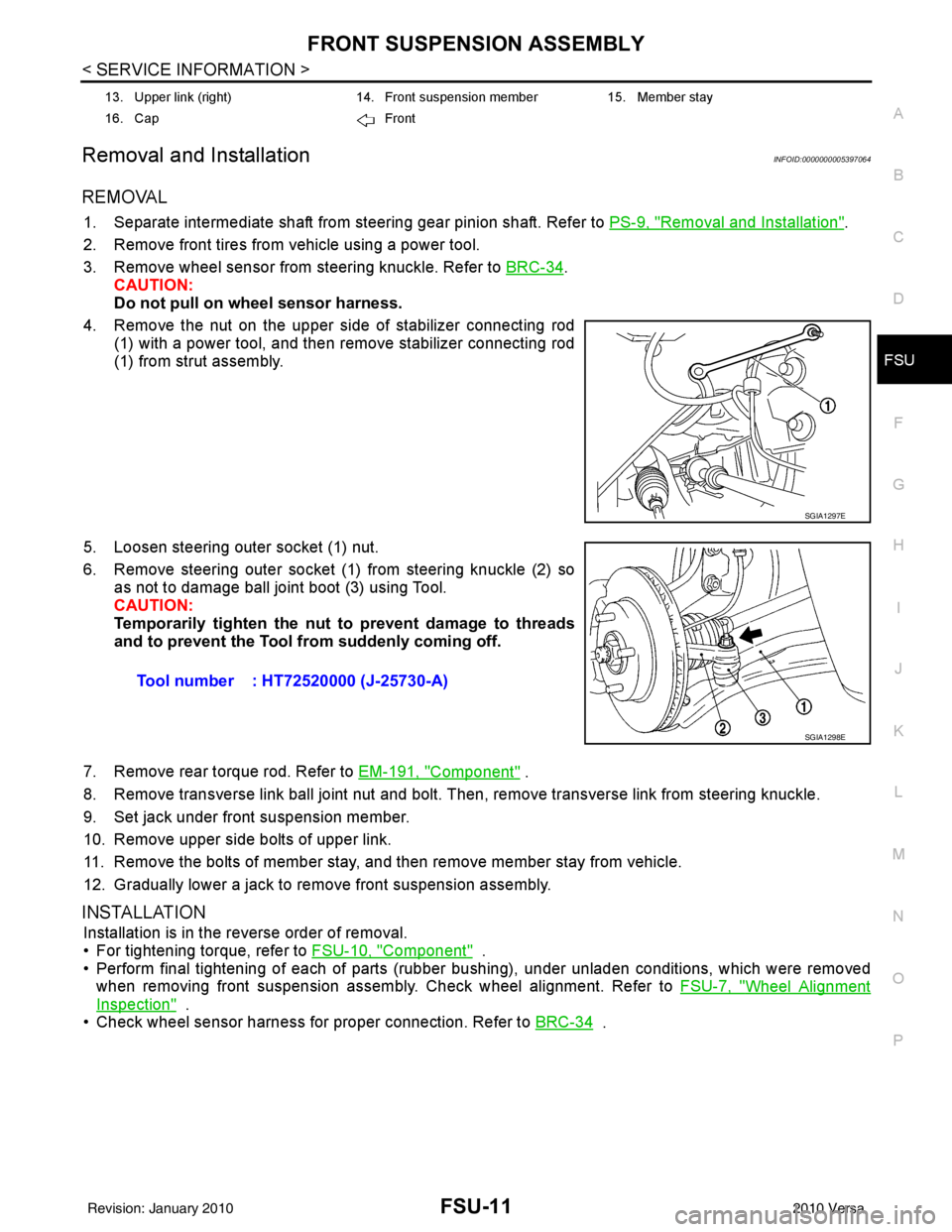
4. Remove the nut on the upper side of stabilizer connecting rod (1) with a power tool, and then remove stabilizer connecting rod
(1) from strut assembly.
5. Loosen steering outer socket (1) nut.
6. Remove steering outer socket (1) from steering knuckle (2) so as not to damage ball joint boot (3) using Tool.
CAUTION:
Temporarily tighten the nut to prevent damage to threads
and to prevent the Tool fr om suddenly coming off.
7. Remove rear torque rod. Refer to EM-191, "
Component" .
8. Remove transverse link ball joint nut and bolt. Then, remove transverse link from steering knuckle.
9. Set jack under front suspension member.
10. Remove upper side bolts of upper link.
11. Remove the bolts of member stay, and then remove member stay from vehicle.
12. Gradually lower a jack to remove front suspension assembly.
INSTALLATION
Installation is in the reverse order of removal.
• For tightening torque, refer to FSU-10, "
Component" .
• Perform final tightening of each of parts (rubber bushing), under unladen conditions, which were removed when removing front suspension assembly. Check wheel alignment. Refer to FSU-7, "
Wheel Alignment
Inspection" .
• Check wheel sensor harness for proper connection. Refer to BRC-34
.
13. Upper link (right)14. Front suspension member15. Member stay
16. Cap Front
SGIA1297E
Tool number : HT72520000 (J-25730-A)
SGIA1298E
Revision: January 20102010 Versa
Page 2659 of 3745
FSU-12
< SERVICE INFORMATION >
COIL SPRING AND STRUT
COIL SPRING AND STRUT
Removal and InstallationINFOID:0000000005397065
REMOVAL
1. Remove cowl top panel. Refer to EI-22, "Removal and Installation" .
2. Remove front tires using power tool.
3. Remove harness of wheel sensor from strut assembly. Refer to BRC-34, "
Removal and Installation" .
CAUTION:
Do not pull on wheel sensor harness.
4. Remove brake hose lock plate. Refer to BR-12, "
Rear Brake Tube and Hose" .
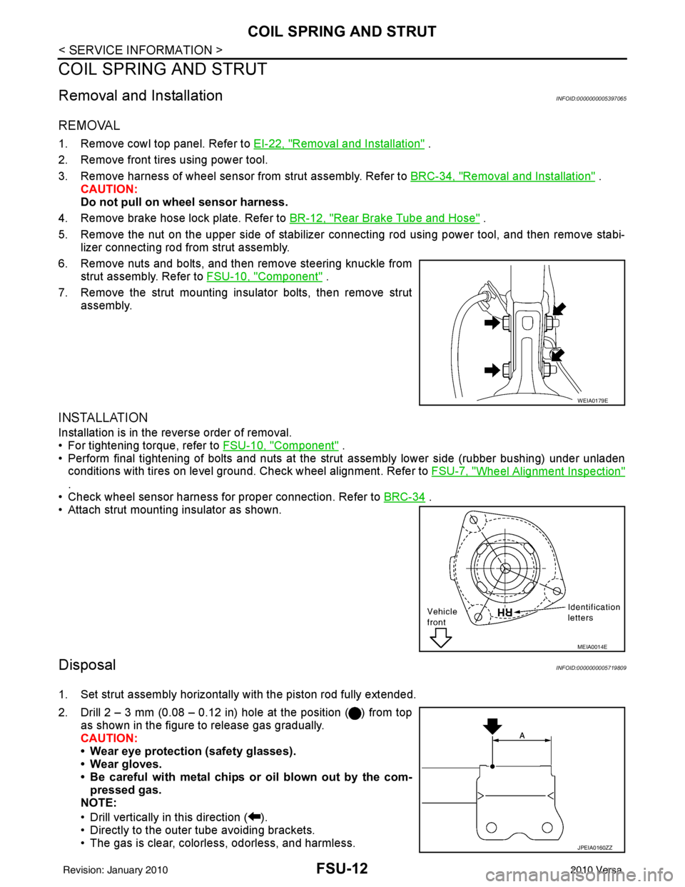
5. Remove the nut on the upper side of stabilizer connecting rod using power tool, and then remove stabi- lizer connecting rod from strut assembly.
6. Remove nuts and bolts, and then remove steering knuckle from strut assembly. Refer to FSU-10, "
Component" .
7. Remove the strut mounting insulator bolts, then remove strut assembly.
INSTALLATION
Installation is in the reverse order of removal.
• For tightening torque, refer to FSU-10, "
Component" .
• Perform final tightening of bolts and nuts at the strut assembly lower side (rubber bushing) under unladen
conditions with tires on level ground. Check wheel alignment. Refer to FSU-7, "
Wheel Alignment Inspection"
.
• Check wheel sensor harness for proper connection. Refer to BRC-34
.
• Attach strut mounting insulator as shown.
DisposalINFOID:0000000005719809
1. Set strut assembly horizontally with the piston rod fully extended.
2. Drill 2 – 3 mm (0.08 – 0.12 in) hole at the position ( ) from top as shown in the figure to release gas gradually.
CAUTION:
• Wear eye protection (safety glasses).
• Wear gloves.
• Be careful with metal chips or oil blown out by the com-pressed gas.
NOTE:
• Drill vertically in this direction ( ).
• Directly to the outer tube avoiding brackets.
• The gas is clear, colorless, odorless, and harmless.
WEIA0179E
MEIA0014E
JPEIA0160ZZ
Revision: January 20102010 Versa