2010 NISSAN LATIO mirror
[x] Cancel search: mirrorPage 2781 of 3745
GW-64
< SERVICE INFORMATION >
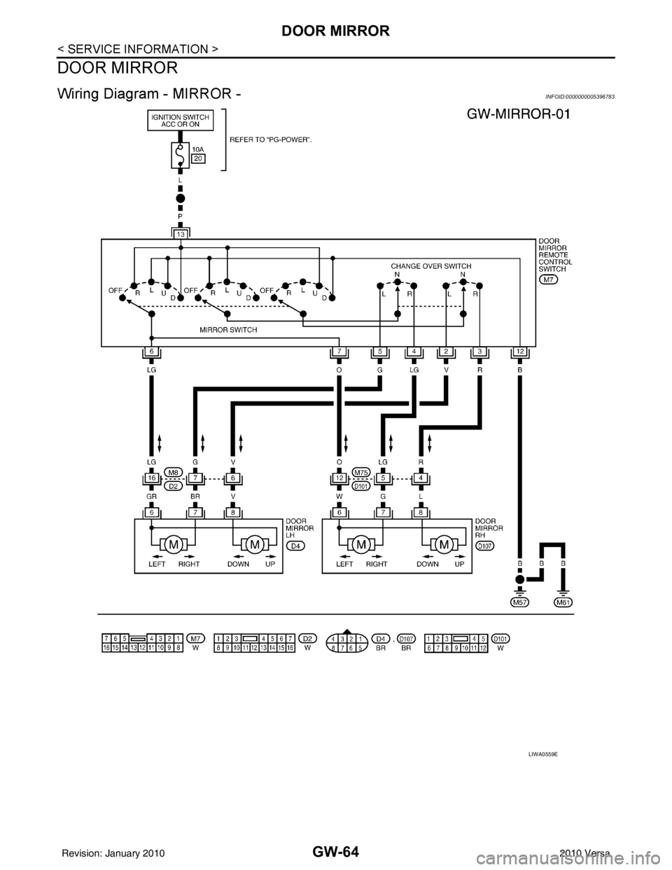
DOOR MIRROR
DOOR MIRROR
Wiring Diagram - MIRROR -INFOID:0000000005396783
LIWA0559E
Revision: January 20102010 Versa
Page 2782 of 3745
DOOR MIRRORGW-65
< SERVICE INFORMATION >
C
DE
F
G H
J
K L
M A
B
GW
N
O P
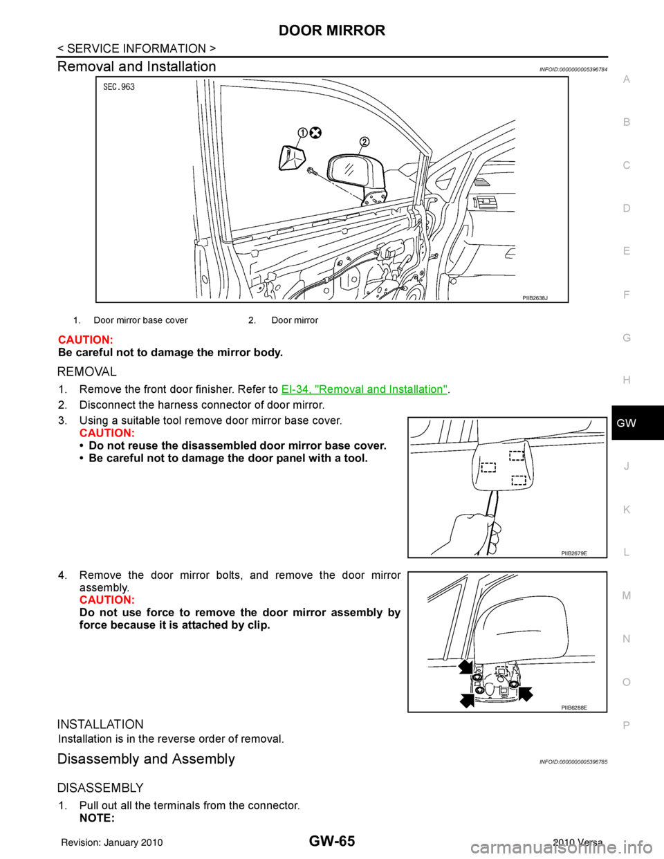
Removal and InstallationINFOID:0000000005396784
CAUTION:
Be careful not to damage the mirror body.
REMOVAL
1. Remove the front door finisher. Refer to EI-34, "Removal and Installation".
2. Disconnect the harness connector of door mirror.
3. Using a suitable tool remove door mirror base cover. CAUTION:
• Do not reuse the disassembl ed door mirror base cover.
• Be careful not to damage the door panel with a tool.
4. Remove the door mirror bolts, and remove the door mirror assembly.
CAUTION:
Do not use force to remove the door mirror assembly by
force because it is attached by clip.
INSTALLATION
Installation is in the reverse order of removal.
Disassembly and AssemblyINFOID:0000000005396785
DISASSEMBLY
1. Pull out all the terminals from the connector.
NOTE:
PIIB2638J
1. Door mirror base cover 2. Door mirror
PIIB2679E
PIIB6288E
Revision: January 20102010 Versa
Page 2783 of 3745

GW-66
< SERVICE INFORMATION >
DOOR MIRROR
Before pulling out the terminal, note the connector terminal arrangement.
2. Turn the mirror glass surface upward.
3. Apply a protective tape A to the housing.
4. Insert a suitable tool B into the concave gap between mirror holder (1) and power unit (2). Push up tabs (3) (2 locations) on
mirror holder to disengage lower part of mirror holder, and
remove mirror body assembly.
NOTE:
When pushing up the tabs, do not forcefully push up only 1 con-
cave position but try to push up 2 concave positions.
5. Remove the mirror body (1) from the mirror housing assembly (2).
6. If necessary, remove screws and mirror actuators.
ASSEMBLY
1. Warm the lower tabs with a dryer or equivalent. NOTE:
Warm the lower tabs sufficiently before installing the mirror body. The tabs may be broken if it is cold. Be
especially careful in the winter.
2. Engage upper tabs of mirror body (1) with power unit (2). Then, press lower part of mirror glass down until the lower part snaps
to allow engagement of lower tabs.
NOTE:
After installation, visually check that the lower tabs are securely
engaged when viewed from the bottom of mirror surface.
3. Insert the harness terminals into the connector. NOTE:
Make sure to insert the harness terminals into the correct con-
nector. Do not confuse the locations.
PIIB6317E
PIIB6096E
PIIB6316E
Revision: January 20102010 Versa
Page 2784 of 3745
INSIDE MIRRORGW-67
< SERVICE INFORMATION >
C
DE
F
G H
J
K L
M A
B
GW
N
O P
INSIDE MIRROR
Removal and InstallationINFOID:0000000005396786
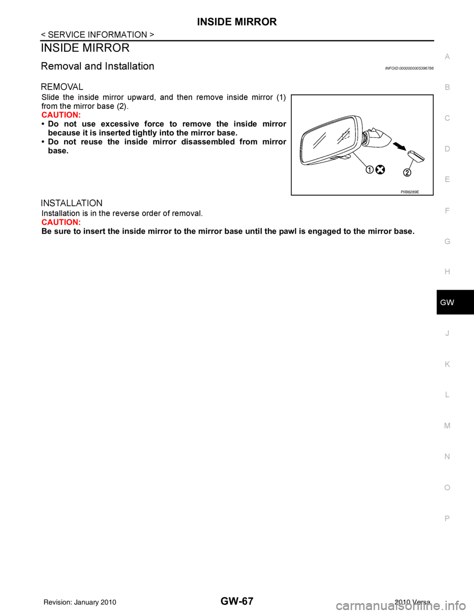
REMOVAL
Slide the inside mirror upward, and then remove inside mirror (1)
from the mirror base (2).
CAUTION:
• Do not use excessive force to remove the inside mirror because it is inserted tigh tly into the mirror base.
• Do not reuse the inside mirror disassembled from mirror base.
INSTALLATION
Installation is in the reverse order of removal.
CAUTION:
Be sure to insert the inside mirror to the mirro r base until the pawl is engaged to the mirror base.
PIIB6289E
Revision: January 20102010 Versa
Page 2997 of 3745

LT-2
Component Parts and Harness Connector Loca-
tion ..........................................................................
51
System Description .................................................51
CAN Communication System Description ..............53
Schematic ............................................................ ...54
Wiring Diagram - TURN - ........................................55
Terminal and Reference Value for BCM .................58
How to Proceed with Trouble Diagnosis .................58
Preliminary Check ..................................................59
CONSULT-III Function (BCM) ................................59
Turn Signals Do Not Operate .................................59
Front Turn Signal Lamp Does Not Operate ............59
Rear Turn Signal Lamp Does Not Operate ............60
Hazard Warning Lamp Does Not Operate But
Turn Signal Lamp Operates ...................................
61
Turn Signal Indicator Lamp Does Not Operate ......62
Bulb Replacement for Front Turn Signal Lamp ......62
Bulb Replacement for Rear Turn Signal Lamp .......62
Removal and Installation of Front Turn Signal
Lamp .......................................................................
62
Removal and Installation of Rear Turn Signal
Lamp .......................................................................
62
LIGHTING AND TURN SIGNAL SWITCH .........63
Removal and Installation ..................................... ...63
HAZARD SWITCH .............................................64
Removal and Installation ..................................... ...64
COMBINATION SWITCH ..................................65
Wiring Diagram - COMBSW - .............................. ...65
Combination Switch Reading Function ...................65
Terminal and Reference Value for BCM .................66
CONSULT-III Function (BCM) ................................66
Combination Switch Inspection ..............................66
Removal and Installation ..................................... ...68
STOP LAMP ......................................................69
Wiring Diagram - STOP/L .................................... ...69
Wiring Diagram - STOP/L .......................................70
Bulb Replacement for High-Mounted Stop Lamp ...70
Bulb Replacement for Rear Combination Lamp for
Stop Lamp ..............................................................
71
Removal and Installation of High-Mounted Stop
Lamp .......................................................................
71
Removal and Installation of Rear Combination
Lamp for Stop Lamp ...............................................
72
BACK-UP LAMP ................................................73
Wiring Diagram - BACK/L - .................................. ...73
Bulb Replacement ..................................................73
Removal and Installation ........................................74
PARKING, LICENSE PLATE AND TAIL
LAMPS ...............................................................
75
Component Parts and Harness Connector Loca-
tion ....................................................................... ...
75
System Description .............................................. ...75
CAN Communication System Description ..............76
Schematic ...............................................................77
Wiring Diagram - TAIL/L - .......................................78
Terminal and Reference Value for BCM .............. ...81
Terminal and Reference Value for IPDM E/R .........81
How to Proceed with Trouble Diagnosis .................82
Preliminary Check ...................................................82
CONSULT-III Function (BCM) ............................. ...82
CONSULT-III Function (IPDM E/R) ........................82
Parking, License Plate and Tail Lamps Do Not Il-
luminate ..................................................................
82
Parking, License Plate and Tail Lamps Do Not
Turn OFF (After Approx. 10 Minutes) .....................
85
Bulb Replacement ................................................ ...85
Removal and Installation .........................................86
REAR COMBINATION LAMP ........................ ...88
Component .......................................................... ...88
Bulb Replacement ...................................................88
Removal and Installation .........................................89
Disassembly and Assembly ................................. ...89
INTERIOR LAMP ...............................................91
Map Lamp ............................................................ ...91
Luggage Room Lamp, Hatch Back .........................91
Trunk Room Lamp, Sedan ......................................92
Vanity Mirror Lamp ..................................................92
INTERIOR ROOM LAMP ...................................94
Component Parts and Harness Connector Loca-
tion ....................................................................... ...
94
System Description .................................................94
Schematic ...............................................................98
Wiring Diagram - INT/L - .........................................99
Terminal and Reference Value for BCM ...............103
How to Proceed with Trouble Diagnosis ...............103
Preliminary Check .................................................104
CONSULT-III Function (BCM) ............................. .104
Interior Room Lamp Control Does Not Operate
(With Map Lamp) ..................................................
105
Interior Room Lamp Control Does Not Operate
(Without Map Lamp) .............................................
107
Bulb Replacement .................................................108
Removal and Installation .......................................109
ILLUMINATION .............................................. ..110
System Description .............................................. .110
CAN Communication System Description ............111
Schematic .............................................................112
Wiring Diagram - ILL - ...........................................113
BULB SPECIFICATIONS ............................... ..117
Headlamp ............................................................. .117
Exterior Lamp ........................................................117
Interior Lamp/Illumination ......................................117
Revision: January 20102010 Versa
Page 3087 of 3745
LT-92
< SERVICE INFORMATION >
INTERIOR LAMP
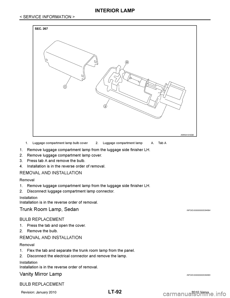
1. Remove luggage compartment lamp from the luggage side finisher LH.
2. Remove luggage compartment lamp cover.
3. Press tab A and remove the bulb.
4. Installation is in the reverse order of removal.
REMOVAL AND INSTALLATION
Removal
1. Remove luggage compartment lamp from the luggage side finisher LH.
2. Disconnect luggage compartment lamp connector.
Installation
Installation is in the reverse order of removal.
Trunk Room Lamp, SedanINFOID:0000000005394984
BULB REPLACEMENT
1. Press the tab and open the cover.
2. Remove the bulb.
REMOVAL AND INSTALLATION
Removal
1. Flex the tab and separate the trunk room lamp from the panel.
2. Disconnect the electrical connector and remove the lamp.
Installation
Installation is in the reverse order of removal.
Vanity Mirror LampINFOID:0000000005394985
BULB REPLACEMENT
1. Luggage compartment lamp bulb cover 2. Luggage compartment lamp A. Tab A
AWKIA1510GB
Revision: January 20102010 Versa
Page 3105 of 3745

LT-110
< SERVICE INFORMATION >
ILLUMINATION
ILLUMINATION
System DescriptionINFOID:0000000005394998
The control of the illumination lamps operation is dependent upon the position of the lighting switch. When the
lighting switch is placed in the 1ST or 2ND position, the BCM (body con\
trol module) receives input signal
requesting the illumination lamps to illuminate. This i nput signal is communicated to IPDM E/R (intelligent
power distribution module engine room) across CAN communication lines. CPU (central processing unit)
located in the IPDM E/R controls the tail lamp relay coil. This relay, when energized, directs power to the illu-
mination lamps, which then illuminate.
Power is supplied at all times
• to ignition relay, located in IPDM E/R,
• to tail lamp relay, located in IPDM E/R,
• through 15A fuse (No. 52, located in IPDM E/R) and
• through 20A fuse (No. 53, located in IPDM E/R)
• to CPU located in IPDM E/R,
• through 40A fusible link (letter g, located in fuse and fusible link box)
• to BCM terminal 70, and
• through 10A fuse [No. 8, located in fuse block (J/B)]
• to BCM terminal 57.
With the ignition switch in the ON or START position, power is supplied
• to ignition relay, located in IPDM E/R, and
• through 10A fuse [No. 6, located in fuse block (J/B)]
• to BCM terminal 38.
With the ignition switch in the ACC or ON position, power is supplied
• through 10A fuse [No. 20, located in fuse block (J/B)]
• to BCM terminal 11.
Ground is supplied
• to BCM terminal 67
• through grounds M57 and M61
• to IPDM E/R terminals 39 and 59, and
• through grounds E15 and E24.
ILLUMINATION OPERATION BY LIGHTING SWITCH
With the lighting switch in the 1ST or 2ND position, BCM receives input signal requesting the illumination
lamps to illuminate. This input signal is communica ted to IPDM E/R across CAN communication lines. CPU
located in the IPDM E/R controls the tail lamp relay coil, which, when energized, directs power
• through 10A fuse (No. 37, located in IPDM E/R)
• through IPDM E/R terminal 29
• to illumination control switch terminal 1
• to VDC OFF switch terminal 3 (with VDC)
• to audio unit (with audio unit) or AV control unit (with premium audio system) terminal 9
• to front air control terminal 5
• to A/T shift selector terminal 3 (with 4-speed A/T)
• to CVT shift selector terminal 3 (with CVT)
• to hazard switch terminal 3
• to combination meter terminal 12
• to door mirror remote control switch terminal 16
• to combination switch (spiral cable) terminal 26 (with steering wheel audio control switches)
• to steering wheel audio control switches through combination switch (spiral cable) terminal 18 (with steering wheel audio control switches).
Ground is supplied
• to VDC OFF switch terminal 4 (with VDC)
• to illumination control switch terminal 3, and
• through grounds M57 and M61.
The illumination control switch controls illumination intensity by varying the ground to the following
• through illumination control switch terminal 2
• to audio unit (with audio unit) or AV control unit (with premium audio system) terminal 8
• to front air control terminal 6
• to A/T shift selector terminal 4 (with 4-speed A/T)
• to CVT shift selector terminal 3 (with CVT)
Revision: January 20102010 Versa
Page 3106 of 3745
ILLUMINATIONLT-111
< SERVICE INFORMATION >
C
DE
F
G H
I
J
L
M A
B
LT
N
O P
• to hazard switch terminal 4
• to combination meter terminal 13
• to door mirror remote control switch terminal 15
• to combination switch (spiral cable) terminal 27 (with steering wheel audio control switches)
• to steering wheel audio control switches through combinat ion switch (spiral cable) terminal 21 (with steering
wheel audio control switches).
With power and ground supplied, illumination lamps illuminate.
EXTERIOR LAMP BATTERY SAVER CONTROL
Refer to LT-75, "System Description".
CAN Communication System DescriptionINFOID:0000000005394999
Refer to LAN-7, "System Description" .
Revision: January 20102010 Versa