2010 NISSAN LATIO change time
[x] Cancel search: change timePage 463 of 3745
![NISSAN LATIO 2010 Service Repair Manual AV-66
< SERVICE INFORMATION >[AUDIO WITH NAVIGATION]
AUDIO
• The majority of the audio malfunctions are the result of outside causes (Malfunction CD, electromagnetic
interference, etc.). Check the s NISSAN LATIO 2010 Service Repair Manual AV-66
< SERVICE INFORMATION >[AUDIO WITH NAVIGATION]
AUDIO
• The majority of the audio malfunctions are the result of outside causes (Malfunction CD, electromagnetic
interference, etc.). Check the s](/manual-img/5/57358/w960_57358-462.png)
AV-66
< SERVICE INFORMATION >[AUDIO WITH NAVIGATION]
AUDIO
• The majority of the audio malfunctions are the result of outside causes (Malfunction CD, electromagnetic
interference, etc.). Check the symptoms below to diagnose the malfunction.
• The vehicle itself can be a source of noise if noise prevention parts or electrical equipment is malfunctioning.
Check if noise is caused and/or changed by engine speed, ignition switch turned to each position, and oper-
ation of each piece of electrical equipment, and then determine the cause.
NOTE:
• CD-R is not guaranteed to play because they can contain compressed audio (MP3, WMA) or could be
incorrectly mastered by the customer on a computer.
• Check if the CDs have the Compact Disc logo. If not , the disc is not mastered to the “red book” Compact
Disc standard and may not play.
NOTE:
Noise resulting from variations in field strength, such as fading noise and multi-path noise, or external noise
from trains and other sources, is not a malfunction.
• Fading noise: This noise occurs because of variations in the field strength in a narrow range due to moun- tains or buildings blocking the signal.
• Multi-path noise: This noise results from a time di fference between the broadcast waves directly from the
station arriving at the antenna and the waves reflected by mountains or buildings.
MALFUNCTION WITH USB
NOTE:
Check that there is no malfunction of USB equi pment main body before performing a diagnosis.
Symptom Probable malfunction location
Audio system does not work normally. • AV control unit power supply and ground circuit. Refer to
AV- 6 7
.
• AV control unit. Refer to AV- 6 7
.
Audio steering wheel switch does not operate proper-
ly. • Remote control signal circuit between steering switch and AV control unit.
Refer to AV- 6 8
.
• Steering wheel audio control switch. Refer to AV- 7 2
.
• AV control unit. Refer to AV- 7 2
.
No sound can be heard from any speakers. • Speaker circuit shorted to ground. Refer to AV- 5 5
.
• AV control unit. Refer to AV- 7 2
.
No sound can be heard from front speakers. • Audio signal circuit between AV control unit and front speakers. Refer to
AV- 6 9
.
• Front speaker. Refer to AV- 7 2
.
• Front tweeter. Refer to AV- 7 2
.
• AV control unit. Refer to AV- 7 2
.
No sound can be heard from rear speakers. • Audio signal circuit between AV control unit and rear speakers. Refer to
AV- 7 1
.
• Rear speaker. Refer to AV- 7 2
.
• AV control unit. Refer to AV- 7 2
.
No sound can be heard from radio or noise is heard. • Antenna feeder. Refer to AV- 9 0
.
• Roof antenna. Refer to AV- 9 0
.
• AV control unit. Refer to AV- 7 2
.
Speed dependent volume system does not function. • Vehicle speed signal circuit between combination meter and AV control
unit. Refer to DI-16
.
• AV control unit. Refer to AV- 7 2
.
• Combination meter. Refer to DI-20
.
There is no sound from the iPod
® or Aux jack. •iPod
® sound signal circuit between AV control unit and Auxiliary jack as-
sembly. Refer to AV- 8 9
.
• AV control unit. Refer to AV- 7 2
.
Revision: January 20102010 Versa
Page 493 of 3745

BCS-4
< SERVICE INFORMATION >
BCM (BODY CONTROL MODULE)
BCM (BODY CONTROL MODULE)
System DescriptionINFOID:0000000005395103
BCM (body control module) controls the operation of various electrical units installed on the vehicle.
BCM FUNCTION
BCM has a combination switch reading function for reading the operation of combination switches (light, wiper,
washer, turn signal) in addition to the function for cont rolling the operation of various electrical components.
Also, it functions as an interface that receives signal s from the front air control, and sends signals to ECM
using CAN communication.
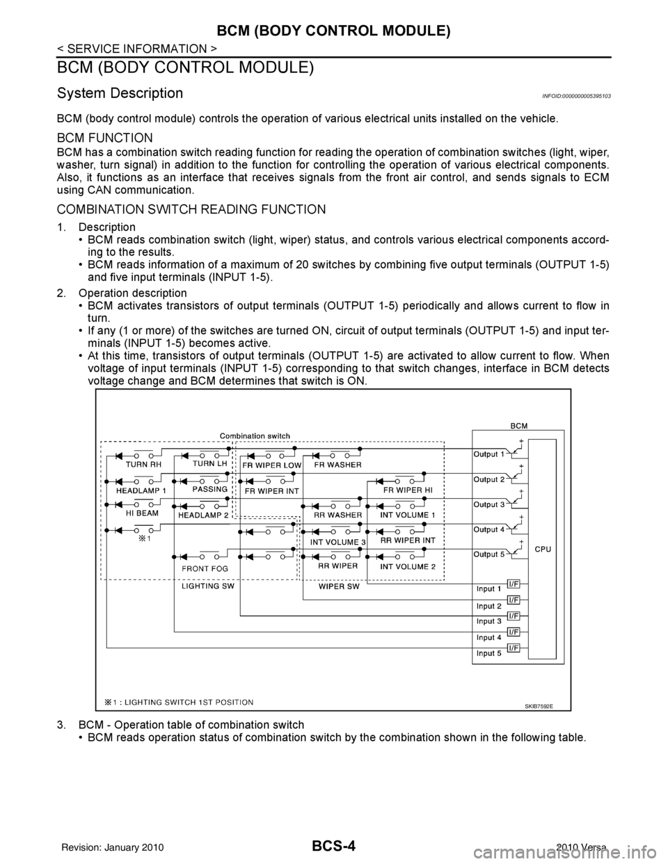
COMBINATION SWITCH READING FUNCTION
1. Description • BCM reads combination switch (light, wiper) status, and controls various electrical components accord-
ing to the results.
• BCM reads information of a maximum of 20 switches by combining five output terminals (OUTPUT 1-5)
and five input terminals (INPUT 1-5).
2. Operation description • BCM activates transistors of output terminals (OUTPU T 1-5) periodically and allows current to flow in
turn.
• If any (1 or more) of the switches are turned ON, circuit of output terminals (OUTPUT 1-5) and input ter- minals (INPUT 1-5) becomes active.
• At this time, transistors of output terminals (OUTPUT 1-5) are activated to allow current to flow. When
voltage of input terminals (INPUT 1-5) corresponding to that switch changes, interface in BCM detects
voltage change and BCM determines that switch is ON.
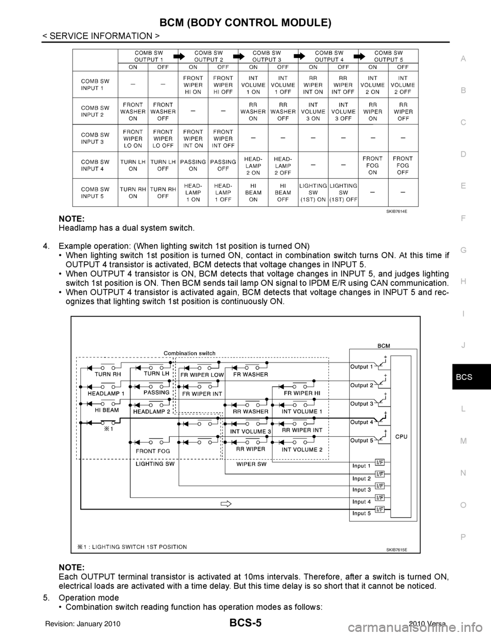
3. BCM - Operation table of combination switch • BCM reads operation status of combination switch by the combination shown in the following table.
SKIB7592E
Revision: January 20102010 Versa
Page 494 of 3745

BCM (BODY CONTROL MODULE)BCS-5
< SERVICE INFORMATION >
C
DE
F
G H
I
J
L
M A
B
BCS
N
O P
NOTE:
Headlamp has a dual system switch.
4. Example operation: (When lighting switch 1st position is turned ON) • When lighting switch 1st position is turned ON, contact in combination switch turns ON. At this time ifOUTPUT 4 transistor is activated, BCM detects that voltage changes in INPUT 5.
• When OUTPUT 4 transistor is ON, BCM detects that voltage changes in INPUT 5, and judges lighting
switch 1st position is ON. Then BCM sends tail lamp ON signal to IPDM E/R using CAN communication.
• When OUTPUT 4 transistor is activated again, BC M detects that voltage changes in INPUT 5 and rec-
ognizes that lighting switch 1st position is continuously ON.
NOTE:
Each OUTPUT terminal transistor is activated at 10ms intervals. Therefore, after a switch is turned ON,
electrical loads are activated with a time delay. But this time delay is so short that it cannot be noticed.
5. Operation mode • Combination switch reading functi on has operation modes as follows:
SKIB7614E
SKIB7615E
Revision: January 20102010 Versa
Page 496 of 3745

BCM (BODY CONTROL MODULE)BCS-7
< SERVICE INFORMATION >
C
DE
F
G H
I
J
L
M A
B
BCS
N
O P
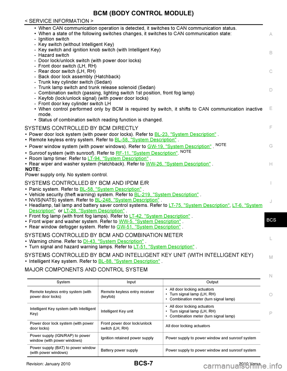
• When CAN communication operation is detected, it switches to CAN communication status.
• When a state of the following switches changes , it switches to CAN communication state:
- Ignition switch
- Key switch (without Intelligent Key)
- Key switch and ignition knob switch (with Intelligent Key)
- Hazard switch
- Door lock/unlock switch (with power door locks)
- Front door switch (LH, RH)
- Rear door switch (LH, RH)
- Back door lock assembly (Hatchback)
- Trunk key cylinder switch (Sedan)
- Trunk lamp switch and trunk release solenoid (Sedan)
- Combination switch (passing, lighting switch 1st position, front fog lamp)
- Keyfob (lock/unlock signal) (with power door locks)
- Front door key cylinder switch LH
• When control performed only by BCM is required by switch, it shifts to CAN communication inactive mode.
• Status of combination switch reading function is changed.
SYSTEMS CONTROLLED BY BCM DIRECTLY
• Power door lock system (with power door locks). Refer to BL-23, "System Description" .
• Remote keyless entry system. Refer to BL-58, "
System Description" .
• Power window system (with power windows). Refer to GW-19, "
System Description" . NOTE
• Sunroof system (with sunroof). Refer to RF-11, "System Description". NOTE
• Room lamp timer. Refer to LT-94, "System Description" .
• Rear wiper and washer system (Hatchback). Refer to WW-26, "
System Description" .
NOTE:
Power supply only. No system control.
SYSTEMS CONTROLLED BY BCM AND IPDM E/R
• Panic system. Refer to BL-58, "System Description" .
• Vehicle security (theft warning) system. Refer to BL-219, "
System Description" .
• NVIS(NATS) system. Refer to BL-248, "
System Description" .
• Headlamp, tail lamp and battery saver control systems. Refer to LT-75, "
System Description", LT- 6 , "System
Description" or LT-28, "System Description" .
• Front fog lamp (with front fog lamps). Refer to LT-42, "
System Description" .
• Front wiper and washer system. Refer to WW-5, "
System Description" .
• Rear window defogger system. Refer to GW-51, "
System Description" .
SYSTEMS CONTROLLED BY BCM AND COMBINATION METER
• Warning chime. Refer to DI-43, "System Description" .
• Turn signal and hazard warning lamps. Refer to LT-51, "
System Description" .
SYSTEMS CONTROLLED BY BCM AND INTELLIGENT KEY UNIT (WITH INTELLIGENT KEY)
• Intelligent Key system. Refer to BL-88, "System Description" .
MAJOR COMPONENTS AND CONTROL SYSTEM
System Input Output
Remote keyless entry system (with
power door locks) Remote keyless entry receiver
(keyfob)• All door locking actuators
• Turn signal lamp (LH, RH)
• Combination meter (turn signal lamp)
Intelligent Key system (with Intelligent
Key) Intelligent Key unit• All door locking actuators
• Turn signal lamp (LH, RH)
• Combination meter (turn signal lamp)
Power door lock system (with power
door locks) Front power door lock/unlock
switch (LH, RH)
All door locking actuators
Power supply (IGN /RAP) to power
window (with power windows) Ignition retained power supply Power supply to power window and sunroof system
Power supply (BAT) to power window
(with power windows) Battery power supply
Power supply to power window and sunroof system
Revision: January 20102010 Versa
Page 519 of 3745

BL-10
< SERVICE INFORMATION >
SQUEAK AND RATTLE TROUBLE DIAGNOSES
Most of these incidents can be repaired by adjusting, securing or insulating the item(s) or component(s) caus-
ing the noise.
SUNROOF/HEADLINING
Noises in the sunroof/headlining area c an often be traced to one of the following:
1. Sunroof lid, rail, linkage or seals making a rattle or light knocking noise
2. Sun visor shaft shaking in the holder
3. Front or rear windshield touching headliner and squeaking
Again, pressing on the components to stop the noise while duplicating the conditions can isolate most of these
incidents. Repairs usually consist of insulating with felt cloth tape.
OVERHEAD CONSOLE (FRONT AND REAR)
Overhead console noises are often caused by the c onsole panel clips not being engaged correctly. Most of
these incidents are repaired by pushing up on the c onsole at the clip locations until the clips engage.
In addition look for:
1. Loose harness or harness connectors.
2. Front console map/reading lamp lense loose.
3. Loose screws at console attachment points.
SEATS
When isolating seat noise it's important to note the pos ition the seat is in and the load placed on the seat when
the noise is present. These conditions should be duplicated when verifying and isolating the cause of the
noise.
Cause of seat noise include:
1. Headrest rods and holder
2. A squeak between the seat pad cushion and frame
3. The rear seatback lock and bracket
These noises can be isolated by moving or pressing on the suspected components while duplicating the con-
ditions under which the noise occurs. Most of thes e incidents can be repaired by repositioning the component
or applying urethane tape to the contact area.
UNDERHOOD
Some interior noise may be caused by components under the hood or on the engine wall. The noise is then
transmitted into the passenger compartment.
Causes of transmitted underhood noise include:
1. Any component mounted to the engine wall
2. Components that pass through the engine wall
3. Engine wall mounts and connectors
4. Loose radiator mounting pins
5. Hood bumpers out of adjustment
6. Hood striker out of adjustment
These noises can be difficult to isolate since they cannot be reached from the interior of the vehicle. The best
method is to secure, move or insulate one component at a time and test drive the \
vehicle. Also, engine RPM
or load can be changed to isolate the noise. Repairs can usually be made by moving, adjusting, securing, or
insulating the component causing the noise.
Revision: January 20102010 Versa
Page 533 of 3745

BL-24
< SERVICE INFORMATION >
POWER DOOR LOCK SYSTEM
When the rear door switch LH is ON (door is OPEN), ground is supplied
• to BCM terminal 48
• through rear door switch LH terminal 1
• through rear door switch LH case ground.
When the rear door switch RH is ON (door is OPEN), ground is supplied
• to BCM terminal 13
• through rear door switch RH terminal 1
• through rear door switch RH case ground.
When the back door switch (hatchback) is ON (back door is OPEN), ground is supplied
• to BCM terminal 43
• through back door switch terminals 3 and 4
• through body grounds B117, B132 and D402.
OUTLINE
Functions available by operating the inside door lock and unlock switches
• Interlocked with the locking operation of door lock and unlock switch, door lock actuators of all doors and
trunk (sedan) are locked.
• Interlocked with the unlocking operation of door lock and unlock switch, door lock actuators of all doors and
trunk (sedan) are unlocked.
Functions available by operating t he front door key cylinder switch LH
• Interlocked with the locking operation of front door key cylinder switch LH, door lock actuators of all doors
and trunk (sedan) are locked.
• When front door key cylinder switch LH is unlo cked, front door lock actuator LH is unlocked.
• When front door key cylinder switch LH is unlocked for the second time within 5 seconds after the first oper- ation, door lock actuators on all doors and trunk (sedan) are unlocked.
Key reminder door system
When door lock and unlock switch is operated to lock doors with ignition key inserted in key cylinder and any
door open, all door lock actuators are locked and then unlocked.
AUTOMATIC DOOR LOCKS (LOCK OPERATION)
The interlock door lock function is the function that locks all doors linked with the vehicle speed.
Vehicle Speed Sensing Auto Door Lock*1
All doors are locked when the vehicle speed reaches 24 km/h (15 MPH) or more.
BCM outputs the lock signal to all door lock actuators when it detects that the ignition switch is turned ON, all
doors are closed and the vehicle speed received from the combination meter via CAN communication
becomes 15 MPH (24 km/h) or more.
If a door is opened and closed at any time during one ignition cycle (OFF → ON), even after initial auto door
lock has taken place, the BCM will relock all doors when the vehicle speed reaches 15 MPH (24 km/h) or more
again.
Setting change of Automatic Door Locks (LOCK) Function
The lock operation setting of the autom atic door locks function can be changed.
With CONSULT-III
The ON/OFF switching of the automatic door locks (LOC K) function and the type selection of the automatic
door locks (LOCK) function can be performed at the WO RK SUPPORT setting of CONSULT-III. Refer to BL-
41, "CONSULT-III Function (BCM)".
Without CONSULT- III
The automatic door locks (LOCK) function can be swit ched ON/OFF by performing the following operation.
1. Close all doors (door switch OFF).
2. Turn ignition switch ON.
3. Within 20 seconds of turning the ignition switch ON, press and hold the door lock and unlock switch to the LOCK position for more than 5 seconds.
4. The switching is completed when the hazard lamps blink.
5. The ignition switch must be turned OFF and ON again between each setting change.
OFF → ON : 2 blinks
ON → OFF : 1 blink
Revision: January 20102010 Versa
Page 578 of 3745

REMOTE KEYLESS ENTRY SYSTEMBL-69
< SERVICE INFORMATION >
C
DE
F
G H
J
K L
M A
B
BL
N
O P
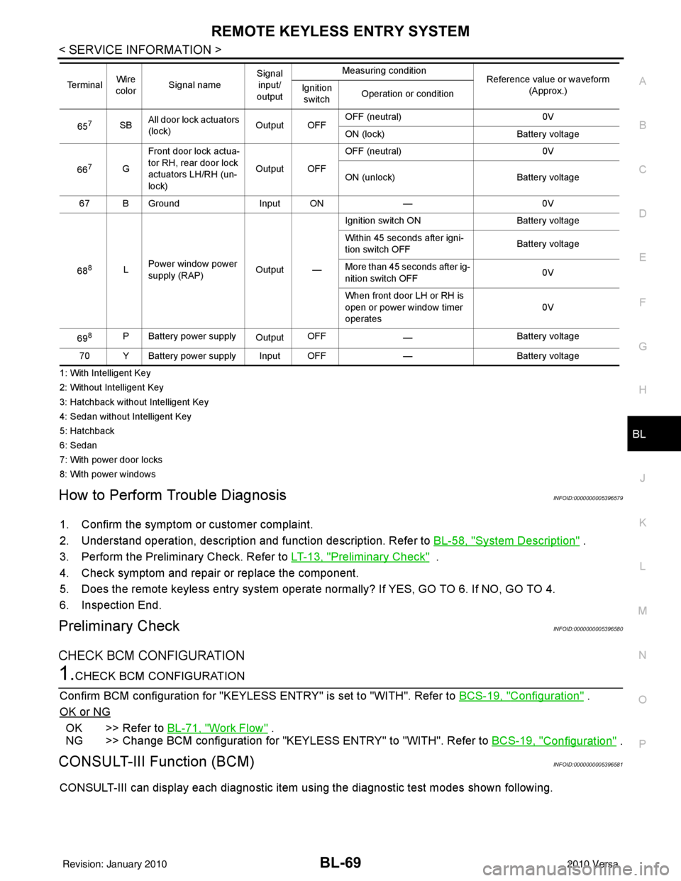
1: With Intelligent Key
2: Without Intelligent Key
3: Hatchback without Intelligent Key
4: Sedan without Intelligent Key
5: Hatchback
6: Sedan
7: With power door locks
8: With power windows
How to Perform Trouble DiagnosisINFOID:0000000005396579
1. Confirm the symptom or customer complaint.
2. Understand operation, description and function description. Refer to BL-58, "
System Description" .
3. Perform the Preliminary Check. Refer to LT-13, "
Preliminary Check" .
4. Check symptom and repair or replace the component.
5. Does the remote keyless entry system operate normally? If YES, GO TO 6. If NO, GO TO 4.
6. Inspection End.
Preliminary CheckINFOID:0000000005396580
CHECK BCM CONFIGURATION
1.CHECK BCM CONFIGURATION
Confirm BCM configuration for "KEYLESS ENTRY" is set to "WITH". Refer to BCS-19, "
Configuration" .
OK or NG
OK >> Refer to BL-71, "Work Flow" .
NG >> Change BCM configuration for "KEYLESS ENTRY" to "WITH". Refer to BCS-19, "
Configuration" .
CONSULT-III Function (BCM)INFOID:0000000005396581
CONSULT-III can display each diagnostic item using the diagnostic test modes shown following.
657SBAll door lock actuators
(lock) Output OFFOFF (neutral)
0V
ON (lock) Battery voltage
66
7G Front door lock actua-
tor RH, rear door lock
actuators LH/RH (un-
lock) Output OFFOFF (neutral)
0V
ON (unlock) Battery voltage
67 B Ground Input ON—0V
68
8L Power window power
supply (RAP)
Output —Ignition switch ON
Battery voltage
Within 45 seconds after igni-
tion switch OFF Battery voltage
More than 45 seconds after ig-
nition switch OFF 0V
When front door LH or RH is
open or power window timer
operates 0V
69
8P Battery power supply OutputOFF
— Battery voltage
70 Y Battery power supply Input OFF —Battery voltage
Te r m i n a l
Wire
color Signal name Signal
input/
output Measuring condition
Reference value or waveform
(Approx.)
Ignition
switch Operation or condition
Revision: January 20102010 Versa
Page 579 of 3745

BL-70
< SERVICE INFORMATION >
REMOTE KEYLESS ENTRY SYSTEM
CONSULT-III APPLICATION ITEMS
Work Support
PANIC ALARM SET
HAZARD LAMP BACK SET
AUTO LOCK SET
TRUNK OPEN
Data Monitor
Diagnostic modeDescription
WORK SUPPORT Supports inspections and adjustments. Commands are transmitted to the BCM for setting
the status suitable for required operation, input/output signals are received from the BCM
and received date is displayed.
DATA MONITOR Displays BCM input/output data in real time.
ACTIVE TEST Operation of electrical loads can be checked by sending drive signal to them.
SELF DIAGNOSTIC RESULT Displays BCM self-diagnosis results.
CAN DIAG SUPPORT MNTR The result of transmit/receive diagnosis of CAN communication can be read. ECU IDENTIFICATION BCM part number can be read.CONFIGURATION Performs BCM configuration read/write functions.
Test Item Description
REMO CONT ID REGIST Keyfob ID code can be registered.
REMO CONT ID ERASER Keyfob ID code can be erased.
REMO CONT ID CONFIR It can be checked whether keyfob ID code is registered or not in this mode.
PANIC ALRM SET Panic alarm operation mode can be changed in this mode. The operation mode will be
changed when
“CURRENT SETTING” on CONSUL T-III screen is touched.
HAZARD LAMP SET Hazard reminder mode can be changed in this mode. The hazard reminder mode will be
changed when
“CURRENT SETTING” on CONSUL T-III screen is touched.
AUTO LOCK SET Auto locking function mode can be changed in this mode. The function mode will be changed
when “CURRENT SETTING” on CONS
ULT-III screen is touched.
TRUNK OPEN Keyless trunk open operation mode can be changed in this mode. The operation mode will
be changed when “CURRENT SETTING” on CONSULT-III screen is touched.
MODE 1
MODE 2MODE 3
Keyfob operation 0.5 secondsNothing1.5 seconds
MODE 1 MODE 2MODE 3 MODE 4
Hazard lamp operation mode NothingUnlock only Lock only Lock and Unlock
MODE 1 MODE 2MODE 3
Auto locking function 30 secondsNothing1 minutes
MODE 1 MODE 2MODE 3
Keyfob operation 0.5 secondsNothing1.5 seconds
Monitored Item Description
IGN ON SW Indicates [ON/OFF] condition of ignition switch in ON position.
KEY ON SW Indicates [ON/OFF] condition of key switch.
ACC ON SW Indicates [ON/OFF] condition of ignition switch in ACC position.
KEYLESS LOCK Indicates [ON/OFF] condition of lock signal from keyfob.
KEYLESS UNLOCK Indicates [ON/OFF] condition of unlock signal from keyfob.
DOOR SW-DR Indicates [ON/OFF] condition of front door switch driver side.
DOOR SW-AS Indicates [ON/OFF] condition of front door switch passenger side.
Revision: January 20102010 Versa