2010 NISSAN LATIO trunk
[x] Cancel search: trunkPage 3009 of 3745

LT-14
< SERVICE INFORMATION >
HEADLAMP (FOR USA)
WORK SUPPORT
Display Item List
CONSULT-III Function (IPDM E/R)INFOID:0000000005612496
CONSULT-III can display each diagnostic item using the diagnostic test modes shown following.
SELF-DIAGNOSTIC RESULTS
Display Item List
Turn signal lamp
Hazard lampFLASHER
××
Blower fan switch sig-
nal
Air conditioner switch
signal AIR CONDITION-
ER
××
Intelligent Key INTELLIGENT
KEY ×
Combination switch COMB SW ×
NVIS (NATS) IMMU ××
Interior lamp battery
saver BATTERY SAV-
ER
××
×
Back door/Trunk TRUNK ××
Theft alarm THEFT ALARM×× ×
Retained accessory
power control RETAINED PWR
×× ×
Oil pressure swit ch SIGNAL BUFFER ××
Low tire pressure moni-
tor AIR PRESSURE
MONITOR
××
× ×
Panic alarm PANIC ALARM ×
System and item
CONSULT-III dis-
play Diagnostic test mode (Inspection by part)
WORK
SUPPORT SELF
−
DIAG RE-
SULTS CAN DIAG
SUPPORT
MNTR DATA
MONITOR ECU
PA R T
NUMBER AC-
TIVE
TEST CON-
FIGU-
RATION
Item Description
RESET SETTING VALUE Return a value set with WORK SUPPORT of each system to a default value in factory shipment.
IPDM E/R diagnostic Mode Description
SELF-DIAG RESULTS Displays IPDM E/R self-diagnosis results. DATA MONITOR Displays IPDM E/R input/output data in real time.
CAN DIAG SUPPORT MNTR The result of transmit/receive diagnosis of CAN communication can be read. ACTIVE TEST Operation of electrical loads can be checked by sending drive signal to them.
Revision: January 20102010 Versa
Page 3080 of 3745
PARKING, LICENSE PLATE AND TAIL LAMPS
LT-85
< SERVICE INFORMATION >
C
D E
F
G H
I
J
L
M A
B
LT
N
O P
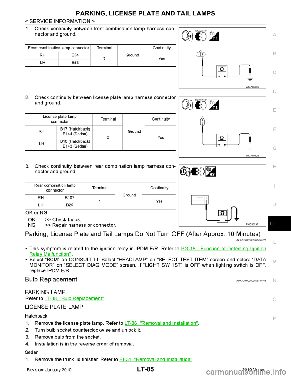
1. Check continuity between front combination lamp harness con- nector and ground.
2. Check continuity between license plate lamp harness connector and ground.
3. Check continuity between rear combination lamp harness con- nector and ground.
OK or NG
OK >> Check bulbs.
NG >> Repair harness or connector.
Parking, License Plate and Tail Lamps Do Not Turn OFF (After Approx. 10 Minutes)
INFOID:0000000005394975
• This symptom is related to the ignition relay in IPDM E/R. Refer to PG-18, "Function of Detecting Ignition
Relay Malfunction" .
• Select “BCM” on CONSULT-III. Select “HEADLAMP” on “SELECT TEST ITEM” screen and select “DATA MONITOR” on “SELECT DIAG MODE” sc reen. If “LIGHT SW 1ST” is OFF when lighting switch is OFF,
replace IPDM E/R.
Bulb ReplacementINFOID:0000000005394976
PA R K I N G L A M P
Refer to LT-88, "Bulb Replacement".
LICENSE PLATE LAMP
Hatchback
1. Remove the license plate lamp. Refer to LT-86, "Removal and Installation".
2. Turn bulb socket counterclockwise and unlock it.
3. Remove bulb from the socket.
4. Installation is in the reverse order of removal.
Sedan
1. Remove the trunk lid finisher. Refer to EI-31, "Removal and Installation".
Front combination lamp connector Terminal
GroundContinuity
RH E54
7Y es
LH E53
WKIA5509E
License plate lamp
connector Te r m i n a l
GroundContinuity
RH B17 (Hatchback)
B144 (Sedan) 2 Yes
LH B16 (Hatchback)
B143 (Sedan)
WKIA5510E
Rear combination lamp connector Te r m i n a l
GroundContinuity
RH B107
1Y es
LH B25
PKIC1029E
Revision: January 20102010 Versa
Page 3083 of 3745
LT-88
< SERVICE INFORMATION >
REAR COMBINATION LAMP
REAR COMBINATION LAMP
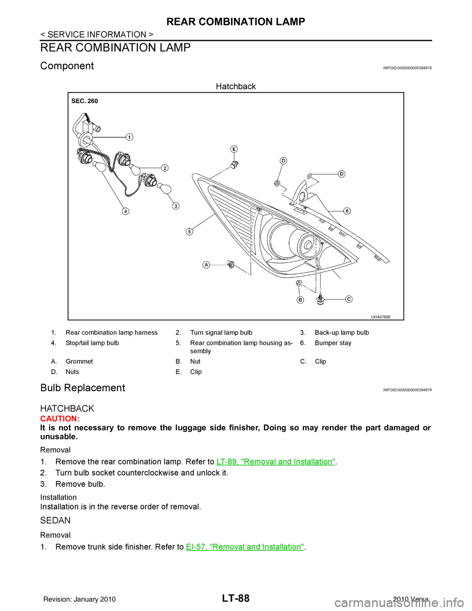
ComponentINFOID:0000000005394978
Hatchback
Bulb ReplacementINFOID:0000000005394979
HATCHBACK
CAUTION:
It is not necessary to remove the luggage side finisher, Doing so may render the part damaged or
unusable.
Removal
1. Remove the rear combination lamp. Refer to LT-89, "Removal and Installation".
2. Turn bulb socket counterclockwise and unlock it.
3. Remove bulb.
Installation
Installation is in the reverse order of removal.
SEDAN
Removal
1. Remove trunk side finisher. Refer to EI-57, "Removal and Installation".
LKIA0760E
1. Rear combination lamp harness 2. Turn signal lamp bulb 3. Back-up lamp bulb
4. Stop/tail lamp bulb 5. Rear combination lamp housing as-
sembly 6. Bumper stay
A. Grommet B. NutC. Clip
D. Nuts E. Clip
Revision: January 20102010 Versa
Page 3084 of 3745
REAR COMBINATION LAMPLT-89
< SERVICE INFORMATION >
C
DE
F
G H
I
J
L
M A
B
LT
N
O P
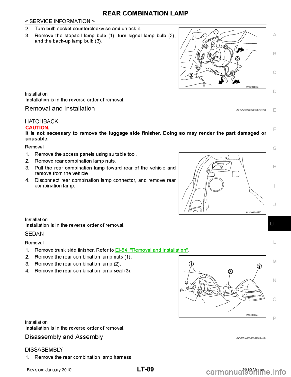
2. Turn bulb socket counterclockwise and unlock it.
3. Remove the stop/tail lamp bulb (1), turn signal lamp bulb (2), and the back-up lamp bulb (3).
Installation
Installation is in the reverse order of removal.
Removal and InstallationINFOID:0000000005394980
HATCHBACK
CAUTION:
It is not necessary to remove the lu ggage side finisher. Doing so may render the part damaged or
unusable.
Removal
1. Remove the access panels using suitable tool.
2. Remove rear combination lamp nuts.
3. Pull the rear combination lamp toward rear of the vehicle and remove from the vehicle.
4. Disconnect rear combination lamp connector, and remove rear combination lamp.
Installation
Installation is in the reverse order of removal.
SEDAN
Removal
1. Remove trunk side finisher. Refer to EI-54, "Removal and Installation".
2. Remove the rear combination lamp nuts (1).
3. Remove the rear combination lamp (2).
4. Remove the rear combination lamp seal (3).
Installation
Installation is in the reverse order of removal.
Disassembly and AssemblyINFOID:0000000005394981
DISSASEMBLY
1. Remove the rear combination lamp harness.
PKIC1034E
ALKIA1859ZZ
PKIC1035E
Revision: January 20102010 Versa
Page 3087 of 3745
LT-92
< SERVICE INFORMATION >
INTERIOR LAMP
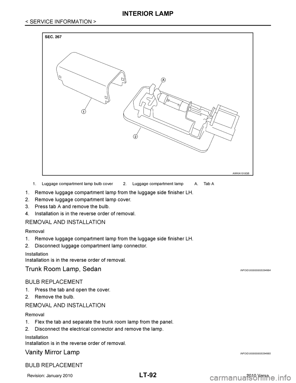
1. Remove luggage compartment lamp from the luggage side finisher LH.
2. Remove luggage compartment lamp cover.
3. Press tab A and remove the bulb.
4. Installation is in the reverse order of removal.
REMOVAL AND INSTALLATION
Removal
1. Remove luggage compartment lamp from the luggage side finisher LH.
2. Disconnect luggage compartment lamp connector.
Installation
Installation is in the reverse order of removal.
Trunk Room Lamp, SedanINFOID:0000000005394984
BULB REPLACEMENT
1. Press the tab and open the cover.
2. Remove the bulb.
REMOVAL AND INSTALLATION
Removal
1. Flex the tab and separate the trunk room lamp from the panel.
2. Disconnect the electrical connector and remove the lamp.
Installation
Installation is in the reverse order of removal.
Vanity Mirror LampINFOID:0000000005394985
BULB REPLACEMENT
1. Luggage compartment lamp bulb cover 2. Luggage compartment lamp A. Tab A
AWKIA1510GB
Revision: January 20102010 Versa
Page 3089 of 3745
LT-94
< SERVICE INFORMATION >
INTERIOR ROOM LAMP
INTERIOR ROOM LAMP
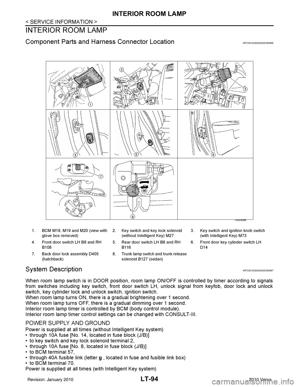
Component Parts and Harness Connector LocationINFOID:0000000005394986
System DescriptionINFOID:0000000005394987
When room lamp switch is in DOOR position, room lamp ON/OFF is controlled by timer according to signals
from switches including key switch, front door switch LH, unlock signal from keyfob, door lock and unlock
switch, key cylinder lock and unlock switch, ignition switch.
When room lamp turns ON, there is a gradual brightening over 1 second.
When room lamp turns OFF, there is a gradual dimming over 1 second.
Interior room lamp timer is controlled by BCM (body control module).
Interior room lamp timer control settings can be changed with CONSULT-III.
POWER SUPPLY AND GROUND
Power is supplied at all times (without Intelligent Key system)
• through 10A fuse [No. 14, located in fuse block (J/B)]
• to key switch and key lock solenoid terminal 2,
• through 10A fuse [No. 8, located in fuse block (J/B)]
• to BCM terminal 57,
• through 40A fusible link (letter g , located in fuse and fusible link box)
• to BCM terminal 70.
Power is supplied at all times (with Intelligent Key system)
1. BCM M18, M19 and M20 (view with
glove box removed) 2. Key switch and key lock solenoid
(without Intelligent Key) M27 3. Key switch and ignition knob switch
(with Intelligent Key) M73
4. Front door switch LH B8 and RH B108 5. Rear door switch LH B6 and RH
B116 6. Front door key cylinder switch LH
D14
7. Back door lock assembly D405 (hatchback) 8. Trunk lamp switch and trunk release
solenoid B127 (sedan)
LIIA2936E
Revision: January 20102010 Versa
Page 3090 of 3745

INTERIOR ROOM LAMPLT-95
< SERVICE INFORMATION >
C
DE
F
G H
I
J
L
M A
B
LT
N
O P
• through 10A fuse (No. 31, located in fuse and fusible link box)
• to key switch and ignition knob switch terminals 2 and 4,
• through 10A fuse [No. 8, located in fuse block (J/B)]
• to BCM terminal 57,
• through 40A fusible link (letter g , located in fuse and fusible link box)
• to BCM terminal 70.
When key is inserted in the key switch and key lock solenoid, power is supplied (without Intelligent Key sys-
tem)
• through key switch and key lock solenoid terminal 1
• to BCM terminal 37.
When key is inserted in the key switch and ignition knob switch, power is supplied (with Intelligent Key system)
• through key switch and ignition knob switch terminal 1
• to BCM terminal 37.
When ignition knob switch is pushed, power is supplied (with Intelligent Key system)
• through key switch and ignition knob switch terminal 3
• to Intelligent Key unit terminal 27.
With the ignition switch in the ON or START position, power is supplied
• through 10A fuse [No. 6, located in fuse block (J/B)]
• to BCM terminal 38.
Ground is supplied
• to BCM terminal 67
• through grounds M57 and M61.
When front door LH is opened, ground is supplied
• to BCM terminal 47
• through front door switch LH terminal 2
• through case ground of front door switch LH.
When front door RH is opened, ground is supplied
• to BCM terminal 12
• through front door switch RH terminal 2
• through case ground of front door switch RH.
When rear door LH is opened, ground is supplied
• to BCM terminal 48
• through rear door switch LH terminal 1
• through case ground of rear door switch LH.
When rear door RH is opened, ground is supplied
• to BCM terminal 13
• through rear door switch RH terminal 1
• through case ground of rear door switch RH.
When back door (hatchback) is opened, ground is supplied
• to BCM terminal 43
• through back door lock assembly (back door switch) terminal 3
• through back door lock assembly (back door switch) terminal 4
• through grounds B117, B132 and D402.
When trunk lid (sedan) is opened, ground is supplied
• to BCM terminal 42
• through trunk lamp switch and trunk release solenoid terminal 3
• through trunk lamp switch and trunk release solenoid terminal 1
• through grounds B117 and B132.
When front door LH is unlocked by front door key cylinder switch LH, the BCM receives a ground signal
• to BCM terminal 7
• through front door key cylinder switch LH terminal 3
• through front door key cylinder switch LH terminal 2
• through grounds M57 and M61.
When a signal, or combination of signals is received by BCM, ground is supplied
• to room lamp terminal 2
• through map lamp terminals 5 and 2 (with map lamp)
• through BCM terminal 63.
With power and ground supplied, the interior room lamp illuminates.
SWITCH OPERATION
When map lamp switch is ON (with map lamp), ground is supplied
• through grounds M57 and M61.
Revision: January 20102010 Versa
Page 3100 of 3745
INTERIOR ROOM LAMPLT-105
< SERVICE INFORMATION >
C
DE
F
G H
I
J
L
M A
B
LT
N
O P
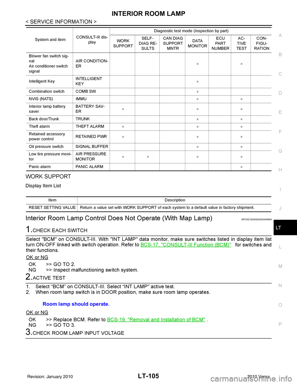
WORK SUPPORT
Display Item List
Interior Room Lamp Control D oes Not Operate (With Map Lamp)INFOID:0000000005394994
1.CHECK EACH SWITCH
Select "BCM" on CONSULT-III. With "I NT LAMP" data monitor, make sure switches listed in display item list
turn ON-OFF linked with switch operation. Refer to BCS-17, "
CONSULT-III Function (BCM)" for switches and
their functions.
OK or NG
OK >> GO TO 2.
NG >> Inspect malfunctioning switch system.
2.ACTIVE TEST
1. Select “BCM” on CONSULT-III. Se lect “INT LAMP" active test.
2. When room lamp switch is in DOOR pos ition, make sure room lamp operates.
OK or NG
OK >> Replace BCM. Refer to BCS-19, "Removal and Installation of BCM" .
NG >> GO TO 3.
3.CHECK ROOM LAMP INPUT VOLTAGE
Blower fan switch sig-
nal
Air conditioner switch
signal AIR CONDITION-
ER
××
Intelligent Key INTELLIGENT
KEY ×
Combination switch COMB SW ×
NVIS (NATS) IMMU ××
Interior lamp battery
saver BATTERY SAV-
ER
××
×
Back door/Trunk TRUNK ××
Theft alarm THEFT ALARM×× ×
Retained accessory
power control RETAINED PWR
×× ×
Oil pressure switch SIGNAL BUFFER ××
Low tire pressure moni-
tor AIR PRESSURE
MONITOR
××
× ×
Panic alarm PANIC ALARM ×
System and item
CONSULT-III dis-
play Diagnostic test mode (Inspection by part)
WORK
SUPPORT SELF
−
DIAG RE-
SULTS CAN DIAG
SUPPORT
MNTR DATA
MONITOR ECU
PA R T
NUMBER AC-
TIVE
TEST CON-
FIGU-
RATION
Item Description
RESET SETTING VALUE Return a value set with WORK SUPPORT of each system to a default value in factory shipment.
Room lamp should operate.
Revision: January 20102010 Versa