Page 747 of 3745
BL-238
< SERVICE INFORMATION >
VEHICLE SECURITY (THEFT WARNING) SYSTEM
*1 : Make sure the system is in the armed phase.
Diagnosis Procedure 1INFOID:0000000005396693
1-1 DOOR SWITCH CHECK (HATCHBACK)
1.CHECK DOOR SWITCHES INPUT SIGNAL
With CONSULT-III
Check door switches ("DOOR SW-DR", "DOOR SW-AS", "DOOR SW-RL", "DOOR SW-RR", "BACK DOOR
SW") in DATA MONITOR mode with CONSULT–III. Refer to BL-41, "
CONSULT-III Function (BCM)".
• When doors are open:
• When doors are closed:
Without CONSULT-III
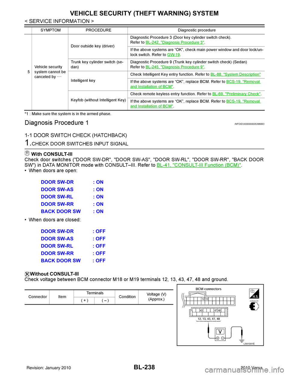
Check voltage between BCM connector M18 or M19 terminals 12, 13, 43, 47, 48 and ground.
5Vehicle security
system cannot be
canceled by ···· Door outside key (driver)
Diagnostic Procedure 3 (Door key cylinder switch check).
Refer to
BL-242, "
Diagnosis Procedure 3".
If the above systems are “OK”, check main power window and door lock/un-
lock switch. Refer to GW-19
.
Trunk key cylinder switch (se-
dan) Diagnostic Procedure 9 (Trunk key cylinder switch check) (Sedan)
Refer to
BL-245, "
Diagnosis Procedure 9".
Intelligent key Check Intelligent Key entry function. Refer to
BL-88, "
System Description"
If the above systems are “OK”, replace BCM. Refer to BCS-19, "Removal
and Installation of BCM".
Keyfob (without Intelligent Key) Check remote keyless entry function. Refer to
BL-69, "
Preliminary Check".
If the above systems are “OK”, replace BCM. Refer to BCS-19, "
Removal
and Installation of BCM".
SYMPTOM
PROCEDURE Diagnostic procedure
DOOR SW-DR : ON
DOOR SW-AS : ON
DOOR SW-RL : ON
DOOR SW-RR : ON
BACK DOOR SW : ON
DOOR SW-DR : OFF
DOOR SW-AS : OFF
DOOR SW-RL : OFF
DOOR SW-RR : OFF
BACK DOOR SW : OFF
Connector ItemTe r m i n a l s
ConditionVoltage (V)
(Approx.)
( + ) ( – )
LIIA1041E
Revision: January 20102010 Versa
Page 753 of 3745
BL-244
< SERVICE INFORMATION >
VEHICLE SECURITY (THEFT WARNING) SYSTEM
OK >> GO TO 3
NG >> Repair or replace harness.
3.CHECK DOOR SWITCHES
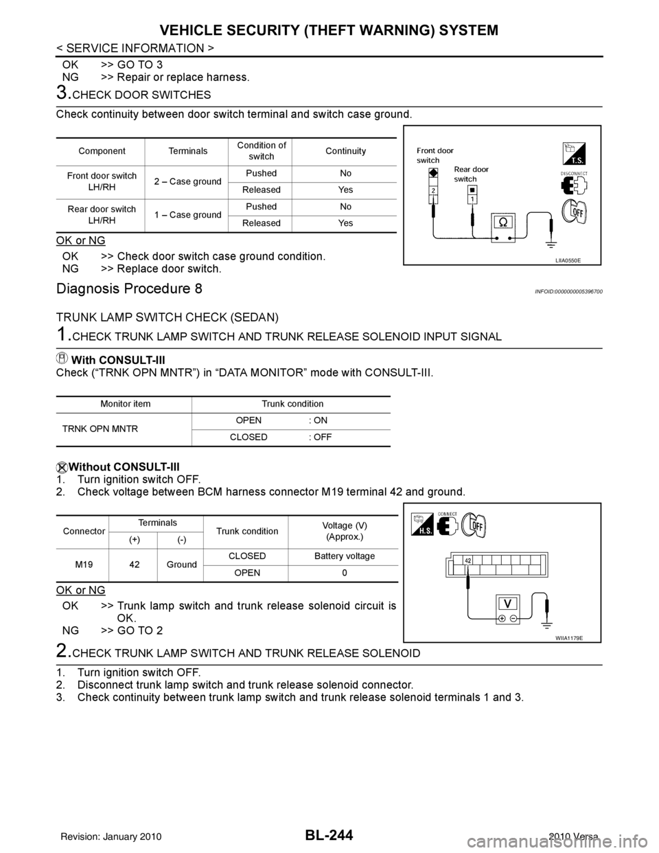
Check continuity between door switch terminal and switch case ground.
OK or NG
OK >> Check door switch case ground condition.
NG >> Replace door switch.
Diagnosis Procedure 8INFOID:0000000005396700
TRUNK LAMP SWITCH CHECK (SEDAN)
1.CHECK TRUNK LAMP SWITCH AND TRUNK RELEASE SOLENOID INPUT SIGNAL
With CONSULT-III
Check (“TRNK OPN MNTR”) in “DATA MONITOR” mode with CONSULT-III.
Without CONSULT-III
1. Turn ignition switch OFF.
2. Check voltage between BCM harness connector M19 terminal 42 and ground.
OK or NG
OK >> Trunk lamp switch and trunk release solenoid circuit is
OK.
NG >> GO TO 2
2.CHECK TRUNK LAMP SWITCH A ND TRUNK RELEASE SOLENOID
1. Turn ignition switch OFF.
2. Disconnect trunk lamp switch and trunk release solenoid connector.
3. Check continuity between trunk lamp switch and trunk release solenoid terminals 1 and 3.
Component TerminalsCondition of
switch Continuity
Front door switch LH/RH 2 – Case ground Pushed
No
Released Yes
Rear door switch LH/RH 1 – Case ground Pushed
No
Released Yes
LIIA0550E
Monitor item Trunk condition
TRNK OPN MNTR OPEN
: ON
CLOSED : OFF
Connector Te r m i n a l s
Trunk condition Voltage (V)
(Approx.)
(+) (-)
M19 42 Ground CLOSED
Battery voltage
OPEN 0
WIIA1179E
Revision: January 20102010 Versa
Page 754 of 3745
VEHICLE SECURITY (THEFT WARNING) SYSTEMBL-245
< SERVICE INFORMATION >
C
DE
F
G H
J
K L
M A
B
BL
N
O P
OK or NG
OK >> GO TO 3
NG >> Replace trunk lamp switch and trunk release solenoid.
3.CHECK TRUNK LAMP SWITCH AND T RUNK RELEASE SOLENOID CIRCUIT
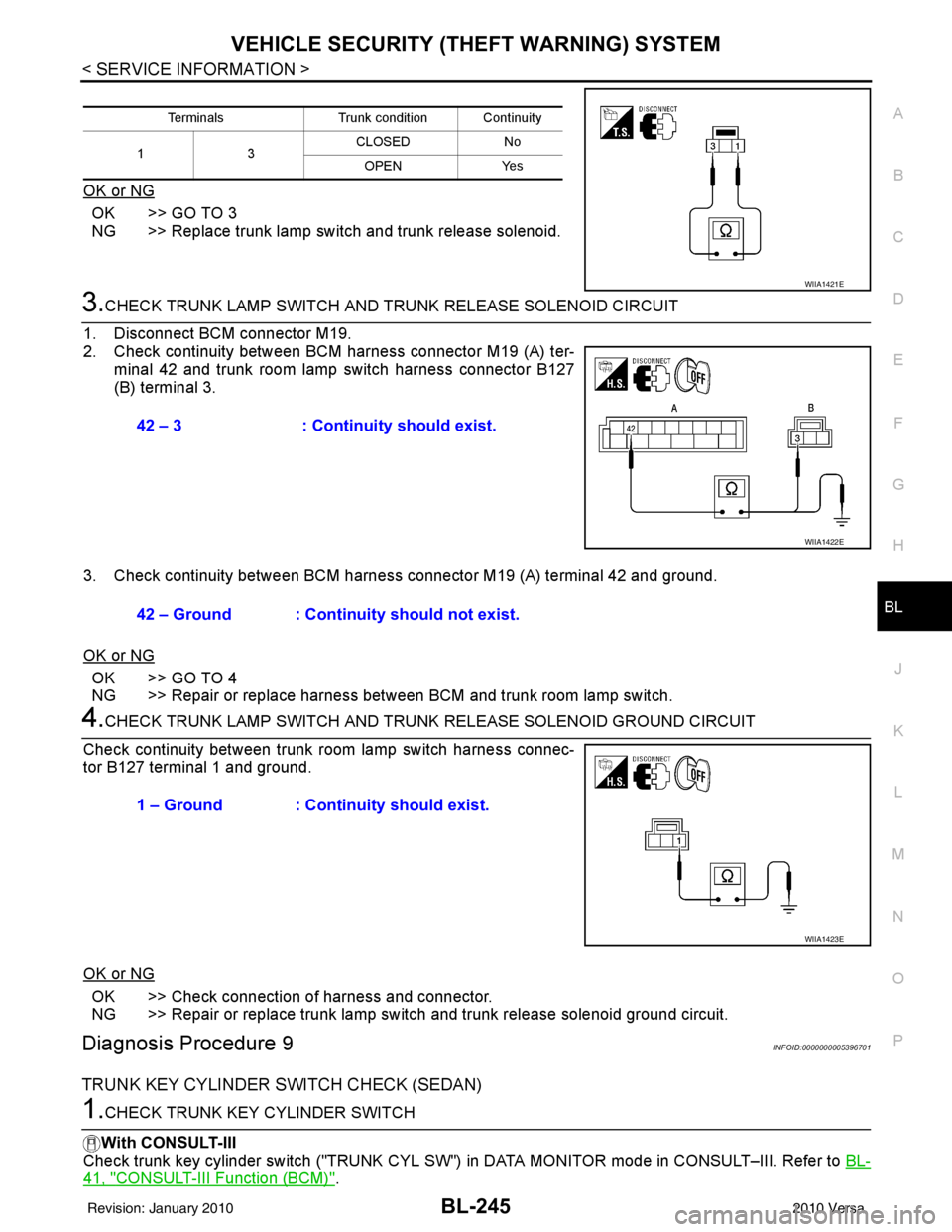
1. Disconnect BCM connector M19.
2. Check continuity between BCM harness connector M19 (A) ter- minal 42 and trunk room lamp switch harness connector B127
(B) terminal 3.
3. Check continuity between BCM harness connector M19 (A) terminal 42 and ground.
OK or NG
OK >> GO TO 4
NG >> Repair or replace harness between BCM and trunk room lamp switch.
4.CHECK TRUNK LAMP SWITCH AND TRUNK RELEASE SOLENOID GROUND CIRCUIT
Check continuity between trunk room lamp switch harness connec-
tor B127 terminal 1 and ground.
OK or NG
OK >> Check connection of harness and connector.
NG >> Repair or replace trunk lamp switch and trunk release solenoid ground circuit.
Diagnosis Procedure 9INFOID:0000000005396701
TRUNK KEY CYLINDER SWITCH CHECK (SEDAN)
1.CHECK TRUNK KEY CYLINDER SWITCH
With CONSULT-III
Check trunk key cylinder switch ("TRUNK CYL SW") in DATA MONITOR mode in CONSULT–III. Refer to BL-
41, "CONSULT-III Function (BCM)".
TerminalsTrunk condition Continuity
13 CLOSED
No
OPEN Yes
WIIA1421E
42 – 3: Continuity should exist.
WIIA1422E
42 – Ground : Continuity should not exist.
1 – Ground : Continuity should exist.
WIIA1423E
Revision: January 20102010 Versa
Page 755 of 3745
BL-246
< SERVICE INFORMATION >
VEHICLE SECURITY (THEFT WARNING) SYSTEM
• When key inserted in trunk key cylinder is turned to FULL STROKE:
• When key is removed from the trunk key cylinder:
Without CONSULT-III
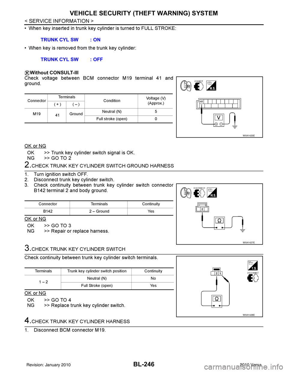
Check voltage between BCM connector M19 terminal 41 and
ground.
OK or NG
OK >> Trunk key cylinder switch signal is OK.
NG >> GO TO 2
2.CHECK TRUNK KEY CYLINDE R SWITCH GROUND HARNESS
1. Turn ignition switch OFF.
2. Disconnect trunk key cylinder switch.
3. Check continuity between trunk key cylinder switch connector B142 terminal 2 and body ground.
OK or NG
OK >> GO TO 3
NG >> Repair or replace harness.
3.CHECK TRUNK KEY CYLINDER SWITCH
Check continuity between trunk key cylinder switch terminals.
OK or NG
OK >> GO TO 4
NG >> Replace trunk key cylinder switch.
4.CHECK TRUNK KEY CYLINDER HARNESS
1. Disconnect BCM connector M19. TRUNK CYL SW : ON
TRUNK CYL SW : OFF
Connector
Te r m i n a l s
ConditionVoltage (V)
(Approx.)
( + ) ( – )
M19 41Ground Neutral (N)
5
Full stroke (open) 0
WIIA1425E
ConnectorTerminalsContinuity
B142 2 – Ground Yes
WIIA1427E
Terminals Trunk key cylinder switch position Continuity
1 – 2 Neutral (N)
No
Full Stroke (open) Yes
WIIA1428E
Revision: January 20102010 Versa
Page 756 of 3745
VEHICLE SECURITY (THEFT WARNING) SYSTEMBL-247
< SERVICE INFORMATION >
C
DE
F
G H
J
K L
M A
B
BL
N
O P
2. Check continuity between BCM connector (A) M19 terminal 41 and trunk key cylinder switch connector (B) B142 terminal 1 and
body ground.
OK or NG
OK >> Trunk key cylinder switch circuit is OK.
NG >> Repair or replace harness.
Connector Terminal Connector Terminal Continuity A: M19 41 B: B142 1
Yes
Ground No
WIIA1429E
Revision: January 20102010 Versa
Page 763 of 3745
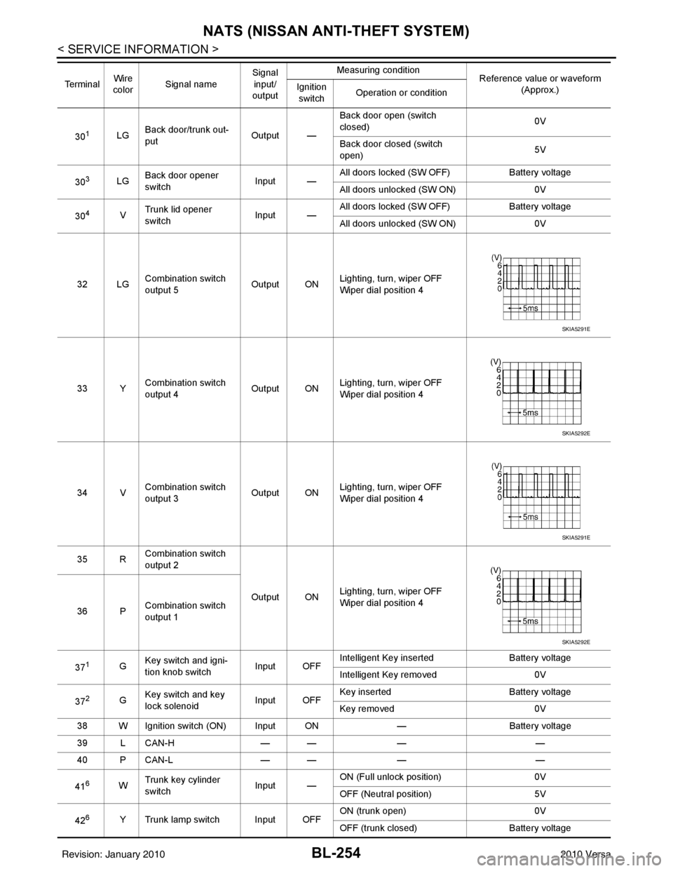
BL-254
< SERVICE INFORMATION >
NATS (NISSAN ANTI-THEFT SYSTEM)
301LGBack door/trunk out-
put Output —Back door open (switch
closed)
0V
Back door closed (switch
open) 5V
30
3LG Back door opener
switch
Input —All doors locked (SW OFF)
Battery voltage
All doors unlocked (SW ON) 0V
30
4V Trunk lid opener
switch
Input —All doors locked (SW OFF)
Battery voltage
All doors unlocked (SW ON) 0V
32 LG Combination switch
output 5 Output ONLighting, turn, wiper OFF
Wiper dial position 4
33 Y Combination switch
output 4 Output ON
Lighting, turn, wiper OFF
Wiper dial position 4
34 V Combination switch
output 3
Output ONLighting, turn, wiper OFF
Wiper dial position 4
35 R Combination switch
output 2
Output ONLighting, turn, wiper OFF
Wiper dial position 4
36 P Combination switch
output 1
37
1G Key switch and igni-
tion knob switch Input OFFIntelligent Key inserted
Battery voltage
Intelligent Key removed 0V
37
2G Key switch and key
lock solenoid Input OFFKey inserted
Battery voltage
Key removed 0V
38 W Ignition switch (ON) Input ON —Battery voltage
39 L CAN-H — —— —
40 P CAN-L — —— —
41
6W Trunk key cylinder
switch
Input —ON (Full unlock position)
0V
OFF (Neutral position) 5V
42
6Y Trunk lamp switch Input OFF ON (trunk open)
0V
OFF (trunk closed) Battery voltage
Te r m i n a l
Wire
color Signal name Signal
input/
output Measuring condition
Reference value or waveform
(Approx.)
Ignition
switch Operation or condition
SKIA5291E
SKIA5292E
SKIA5291E
SKIA5292E
Revision: January 20102010 Versa
Page 764 of 3745
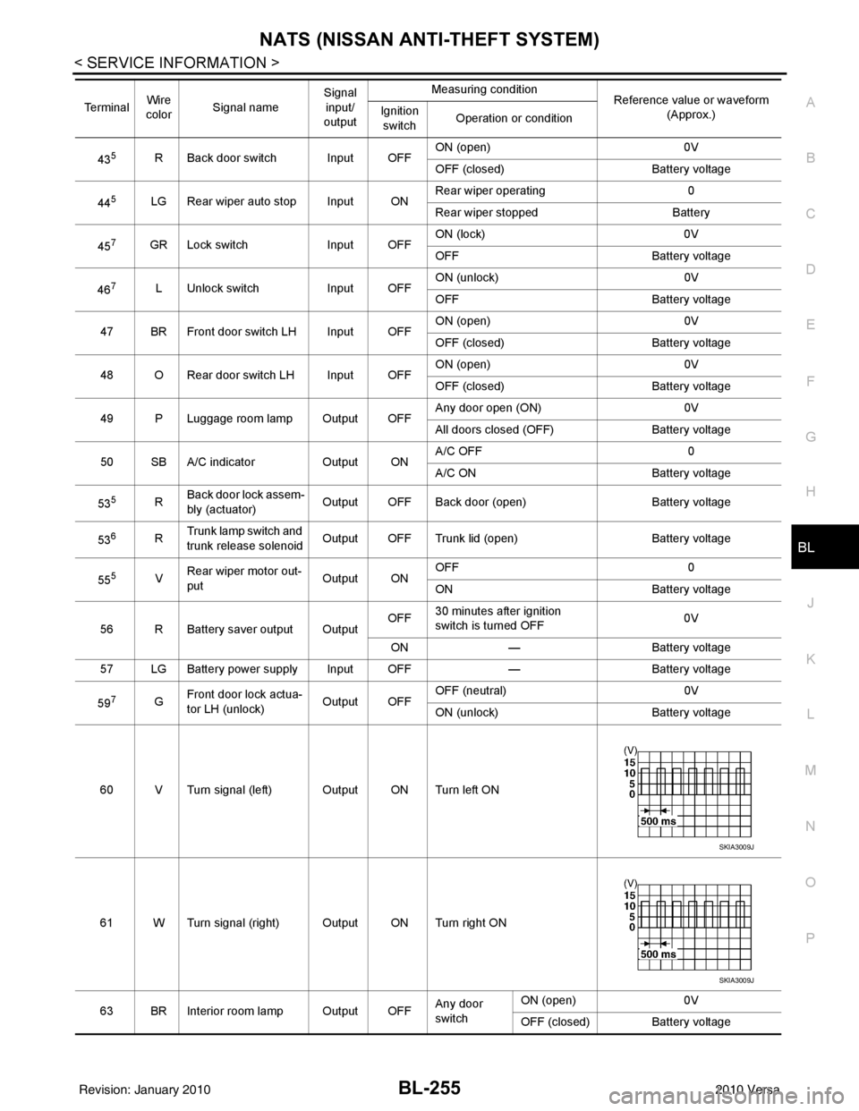
NATS (NISSAN ANTI-THEFT SYSTEM)BL-255
< SERVICE INFORMATION >
C
DE
F
G H
J
K L
M A
B
BL
N
O P
435R Back door switch Input OFF ON (open) 0V
OFF (closed)
Battery voltage
44
5LG Rear wiper auto stop Input ON Rear wiper operating 0
Rear wiper stopped
Battery
45
7GR Lock switch Input OFFON (lock)
0V
OFF Battery voltage
46
7L Unlock switch Input OFFON (unlock)
0V
OFF Battery voltage
47 BR Front door switch LH Input OFF ON (open)
0V
OFF (closed) Battery voltage
48 O Rear door switch LH Input OFF ON (open)
0V
OFF (closed) Battery voltage
49 P Luggage room lamp Output OFF Any door open (ON)
0V
All doors closed (OFF) Battery voltage
50 SB A/C indicator Output ONA/C OFF
0
A/C ON Battery voltage
53
5R Back door lock assem-
bly (actuator)
Output OFF Back door (open)
Battery voltage
53
6R Trunk lamp switch and
trunk release solenoid Output OFF Trunk lid (open)
Battery voltage
55
5V Rear wiper motor out-
put
Output ONOFF
0
ON Battery voltage
56 R Battery saver output Output OFF
30 minutes after ignition
switch is turned OFF 0V
ON — Battery voltage
57 LG Battery power supply Input OFF —Battery voltage
59
7G Front door lock actua-
tor LH (unlock) Output OFFOFF (neutral)
0V
ON (unlock) Battery voltage
60 V Turn signal (left) Output ON Turn left ON
61 W Turn signal (right) Output ON Turn right ON
63 BR Interior room lamp Output OFF Any door
switchON (open)
0V
OFF (closed) Battery voltage
Te r m i n a l
Wire
color Signal name Signal
input/
output Measuring condition
Reference value or waveform
(Approx.)
Ignition
switch Operation or condition
SKIA3009J
SKIA3009J
Revision: January 20102010 Versa
Page 783 of 3745

BL-274
< SERVICE INFORMATION >
BODY REPAIR
7. Front roof rail assembly
8. Sun roof assembly
9. Front roof rail assembly (if equipped with sunroof)
10. Roof side rail reinforcement (RH & LH)
11. Inner center pillar (RH & LH)
12. Hood assembly
13. Center pillar reinforcement (RH & LH)
14. Front pillar inner (RH & LH)
15. Front pillar upper reinforcement (RH & LH)
16. Front pillar lower reinforcement (RH & LH)
17. Fender (RH & LH)
18. Side body (RH & LH)
19. Side body assembly (RH & LH)
20. Outer sill (RH & LH)
21. Outer sill reinforcement (RH & LH)
22. Front door assembly (RH & LH)
23. Outer front door panel (RH & LH)
24. Outer rear door panel (RH & LH)
25. Rear door assembly (RH & LH)
26. Rear fender (RH & LH)
27. Rear fender corner (RH & LH)
28. Rear combination lamp base (RH & LH)
29. Rear wheel housing front extension (RH & LH)
30. Rear wheel housing outer (RH & LH)
31. Rear pillar inner reinforcement (RH & LH)
32. Rear body side inner (RH & LH)
33. Rear wheel housing inner (RH & LH)
34. Rear panel assembly
35. Rear bumper fascia upper bracket
36. Rear bumper fascia center bracket
37. Trunk lid assembly
38. Parcel shelf side (RH & LH)
39. Parcel shelf assembly
40. Rear waist panel
41. Rear bumper fascia lower bracket
Corrosion ProtectionINFOID:0000000005396720
DESCRIPTION
To provide improved corrosion prevention, the following anti-corrosive measures have been implemented in
NISSAN production plants. When repairing or replacing body panels, it is necessary to use the same anti-cor-
rosive measures.
ANTI-CORROSIVE PRECOATED STEEL (GALVANNEALED STEEL)
Revision: January 20102010 Versa