Page 218 of 3745
TROUBLE DIAGNOSIS FOR SYMPTOMSAT-201
< SERVICE INFORMATION >
DE
F
G H
I
J
K L
M A
B
AT
N
O P
- Overrun clutch control valve
- Overrun clutch solenoid valve
3. Disassemble A/T. Refer to AT-257, "
Disassembly" .
4. Check the following items:
- Servo piston assembly
- Brake band
OK or NG
OK >> GO TO 7.
NG >> Repair or replace damaged parts.
7.CHECK SYMPTOM
Check again. Refer to AT-62, "
Cruise Test - Part 3" .
OK or NG
OK >> INSPECTION END
NG >> GO TO 8.
8.CHECK TCM
1. Check TCM input/output signals. Refer to AT-75, "
TCM Terminal and Reference Value" .
2. If NG, recheck TCM pin terminals for dam age or loose connection with harness connector.
OK or NG
OK >> INSPECTION END
NG >> Repair or replace damaged parts.
Vehicle Does Not Decelerate by Engine BrakeINFOID:0000000005397411
SYMPTOM:
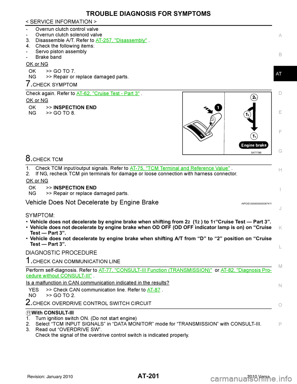
• Vehicle does not decelerate by engine brake when shifting from 22 (12 ) to 11“Cruise Test — Part 3”.
• Vehicle does not decelerate by engi ne brake when OD OFF (OD OFF indicator lamp is on) on “Cruise
Test — Part 3”.
• Vehicle does not decelerate by engi ne brake when shifting A/T from “D” to “2” position on “Cruise
Test — Part 3”.
DIAGNOSTIC PROCEDURE
1.CHECK CAN COMMUNICATION LINE
Perform self-diagnosis. Refer to AT-77, "
CONSULT-III Function (TRANSMISSION)" or AT-82, "Diagnosis Pro-
cedure without CONSULT-III" .
Is a malfunction in CAN communication indicated in the results?
YES >> Check CAN communication line. Refer to AT- 8 7 .
NO >> GO TO 2.
2.CHECK OVERDRIVE CO NTROL SWITCH CIRCUIT
With CONSULT-III
1. Turn ignition switch ON. (Do not start engine)
2. Select “TCM INPUT SIGNALS” in “DATA MONI TOR” mode for “TRANSMISSION” with CONSULT-III.
3. Read out “OVERDRIVE SW”.
Check the signal of the overdrive control switch is indicated properly.
SAT778B
Revision: January 20102010 Versa
Page 219 of 3745
AT-202
< SERVICE INFORMATION >
TROUBLE DIAGNOSIS FOR SYMPTOMS
Without CONSULT-III
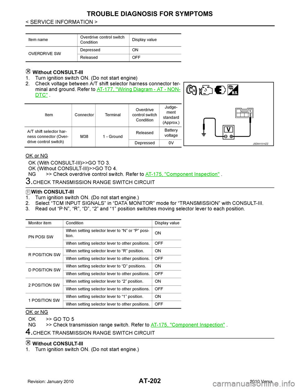
1. Turn ignition switch ON. (Do not start engine)
2. Check voltage between A/T shift selector harness connector ter-
minal and ground. Refer to AT-177, "
Wiring Diagram - AT - NON-
DTC" .
OK or NG
OK (With CONSULT-III)>>GO TO 3.
OK (Without CONSULT-III)>>GO TO 4.
NG >> Check overdrive control switch. Refer to AT-175, "
Component Inspection" .
3.CHECK TRANSMISSION RANGE SWITCH CIRCUIT
With CONSULT-III
1. Turn ignition switch ON. (Do not start engine.)
2. Select “TCM INPUT SIGNALS” in “DATA MONITOR” mode for “TRANSMISSION” with CONSULT-III.
3. Read out “P·N”, “R”, “D”, “2” and “1” position switches moving selector lever to each position.
OK or NG
OK >> GO TO 5
NG >> Check transmission range switch. Refer to AT-175, "
Component Inspection" .
4.CHECK TRANSMISSION RANGE SWITCH CIRCUIT
Without CONSULT-III
1. Turn ignition switch ON. (Do not start engine.)
Item name Overdrive control switch
ConditionDisplay value
OVERDRIVE SW Depressed
ON
Released OFF
ItemConnector Terminal Overdrive
control switch
Condition Judge-
ment
standard
(Approx.)
A/T shift selector har-
ness connector (Over-
drive control switch) M38 1 - Ground
Released
Battery
voltage
Depressed 0V
JSDIA1514ZZ
Monitor item Condition Display value
PN POSI SW When setting selector le
ver to “N” or “P” posi-
tion. ON
When setting selector lever to other positions. OFF
R POSITION SW When setting selector lever to “R” position. ON
When setting selector lever to other positions. OFF
D POSITION SW When setting selector lever to “D” positions. ON
When setting selector lever to other positions. OFF
2 POSITION SW When setting selector lever to “2” position. ON
When setting selector lever to other positions. OFF
1 POSITION SW When setting selector lever to “1” position. ON
When setting selector lever to other positions. OFF
Revision: January 20102010 Versa
Page 220 of 3745

TROUBLE DIAGNOSIS FOR SYMPTOMSAT-203
< SERVICE INFORMATION >
DE
F
G H
I
J
K L
M A
B
AT
N
O P
2. Check voltage between TCM connector terminals and ground while moving selector lever through each position. Refer to AT-
91, "Wiring Diagram - AT - TR/SW" .
B: Battery voltage
0: 0V
OK or NG
OK >> GO TO 5
NG >> Check transmission range switch. Refer to AT-175, "
Component Inspection" .
5.CHECK A/T POSITION
Check A/T position. Refer to AT-217, "
Checking of A/T Position" .
OK or NG
OK >> GO TO 6.
NG >> Adjust A/T position. Refer to AT-217, "
Adjustment of A/T Position" .
6.CHECK OUTPUT SPEED SENSOR AND VEHICLE SPEED SIGNAL CIRCUIT
Check output speed sensor and vehicle speed signal circuit. Refer to AT-100
and/or AT- 1 5 3 .
OK or NG
OK >> GO TO 7.
NG >> Repair or replace output speed sensor and/or vehicle speed signal circuits.
7.CHECK ACCELERATOR PEDAL POSITION SENSOR
Check accelerator pedal position sensor. Refer to EC-405, "
Description" (HR16DE), EC-982, "Component
Description" (MR18DE).
OK or NG
OK >> GO TO 8.
NG >> Repair or replace accelerator pedal position sensor.
8.CHECK A/T FLUID CONDITION
1. Remove oil pan. Refer to AT-237, "
Component" .
2. Check A/T fluid condition. Refer to AT-51, "
Inspections Before Trouble Diagnosis" .
OK or NG
OK >> GO TO 10.
NG >> GO TO 9.
9.DETECT MALFUNCTIONING ITEM
1. Remove control valve assembly. Refer to AT-222, "
Control Valve Assembly and Accumulators" .
2. Check the following.
- Shift valve A
Selector lever position Te r m i n a l
36 35 34 27 26
“P”, “N” B 0 0 0 0
“R” 0B000
“D” 0 0 B 0 0
“2” 0 0 0 B 0
“1” 0 0 0 0 B
SCIA7162E
Revision: January 20102010 Versa
Page 221 of 3745
AT-204
< SERVICE INFORMATION >
TROUBLE DIAGNOSIS FOR SYMPTOMS
- Overrun clutch solenoid valve
3. Disassemble A/T. Refer to AT-257, "
Disassembly" .
4. Check the following.
- Overrun clutch assembly. Refer to AT-307, "
Forward and Overrun Clutches" .
- Low & reverse brake assembly. Refer to AT-314, "
Low & Reverse Brake" .
OK or NG
OK >> GO TO 10.
NG >> Repair or replace damaged parts.
10.CHECK SYMPTOM
Check again. Refer to AT-62, "
Cruise Test - Part 3" .
OK or NG
OK >> INSPECTION END
NG >> GO TO 11.
11 .CHECK TCM
1. Check TCM input/output signals. Refer to AT-75, "
TCM Terminal and Reference Value" .
2. If NG, recheck TCM pin terminals for damage or loose connection with harness connector.
OK or NG
OK >> INSPECTION END
NG >> Repair or replace damaged parts.
TCM Self-Diagnosis Does Not ActivateINFOID:0000000005397412
SYMPTOM:
OD OFF indicator lamp does not come on in TCM sel f-diagnostic procedure even if the lamp circuit is
good.
DESCRIPTION
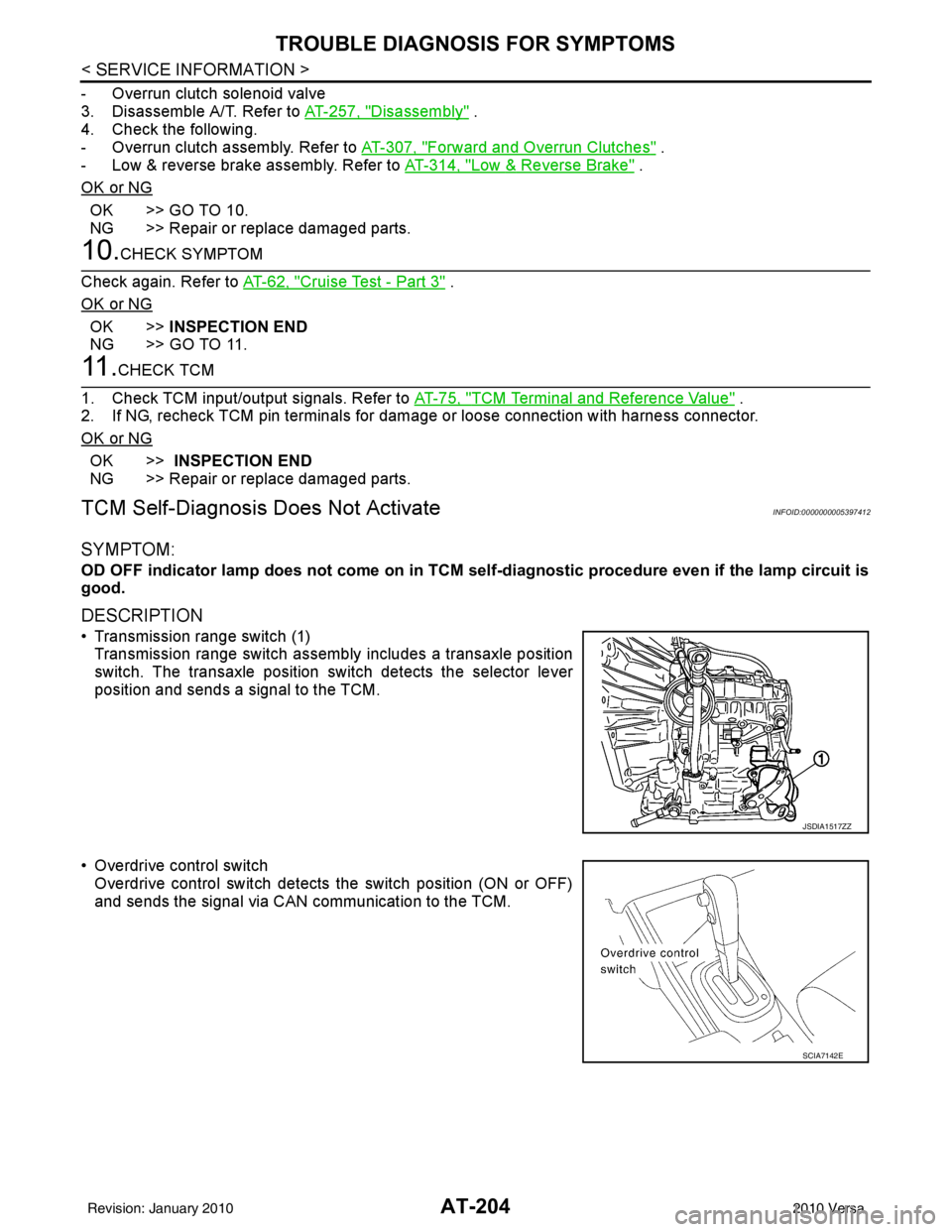
• Transmission range switch (1) Transmission range switch assembly includes a transaxle position
switch. The transaxle position swit ch detects the selector lever
position and sends a signal to the TCM.
• Overdrive control switch Overdrive control switch detects the switch position (ON or OFF)
and sends the signal via CAN communication to the TCM.
JSDIA1517ZZ
SCIA7142E
Revision: January 20102010 Versa
Page 229 of 3745
AT-212
< SERVICE INFORMATION >
TRANSMISSION CONTROL MODULE
TRANSMISSION CONTROL MODULE
Removal and InstallationINFOID:0000000005397417
COMPONENTS
REMOVAL
1. Disconnect the battery negative terminal.
2. Disconnect TCM harness connectors (1) from TCM (2).• Instrument lower finisher (3)
3. Remove TCM (2).
INSTALLATION
Installation is in the reverse order of removal.
1. TCM
SCIA6963E
SCIA7167E
Revision: January 20102010 Versa
Page 242 of 3745
ON-VEHICLE SERVICEAT-225
< SERVICE INFORMATION >
DE
F
G H
I
J
K L
M A
B
AT
N
O P
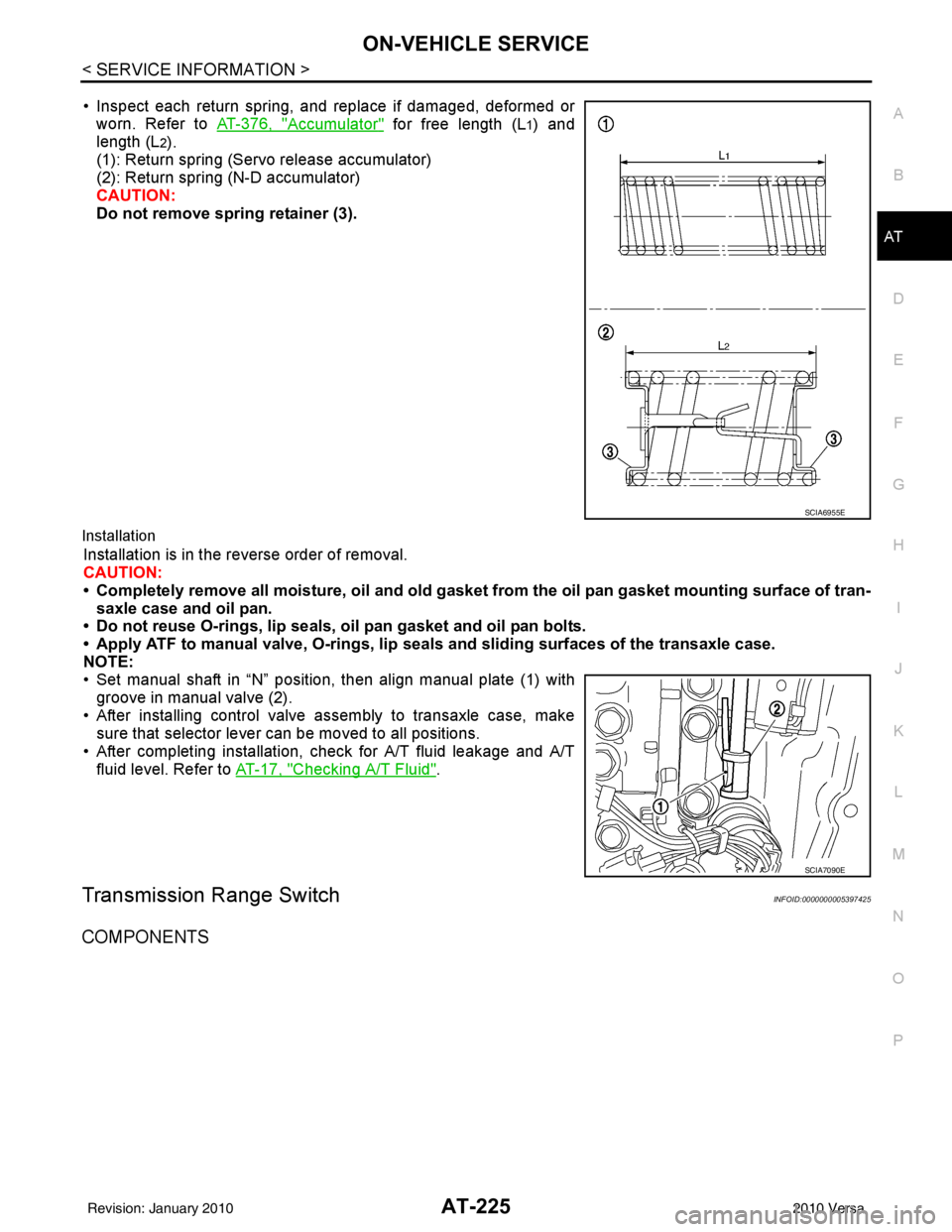
• Inspect each return spring, and replace if damaged, deformed or worn. Refer to AT-376, "
Accumulator" for free length (L1) and
length (L
2).
(1): Return spring (Servo release accumulator)
(2): Return spring (N-D accumulator)
CAUTION:
Do not remove spring retainer (3).
Installation
Installation is in the reverse order of removal.
CAUTION:
• Completely remove all moisture, oil and old gasket from the oil pan gasket mounting surface of tran-
saxle case and oil pan.
• Do not reuse O-rings, lip seals, oil pan gasket and oil pan bolts.
• Apply ATF to manual valve, O-rings, lip seals and sliding surfaces of the transaxle case.
NOTE:
• Set manual shaft in “N” position, then align manual plate (1) with groove in manual valve (2).
• After installing control valve assembly to transaxle case, make sure that selector lever can be moved to all positions.
• After completing installation, check for A/T fluid leakage and A/T fluid level. Refer to AT-17, "
Checking A/T Fluid".
Transmission Range SwitchINFOID:0000000005397425
COMPONENTS
SCIA6955E
SCIA7090E
Revision: January 20102010 Versa
Page 243 of 3745
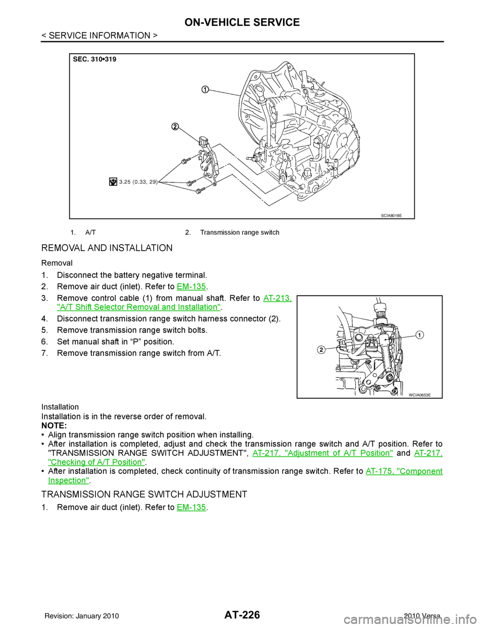
AT-226
< SERVICE INFORMATION >
ON-VEHICLE SERVICE
REMOVAL AND INSTALLATION
Removal
1. Disconnect the battery negative terminal.
2. Remove air duct (inlet). Refer to EM-135
.
3. Remove control cable (1) from manual shaft. Refer to AT-213,
"A/T Shift Selector Removal and Installation".
4. Disconnect transmission range switch harness connector (2).
5. Remove transmission range switch bolts.
6. Set manual shaft in “P” position.
7. Remove transmission range switch from A/T.
Installation
Installation is in the reverse order of removal.
NOTE:
• Align transmission range switch position when installing.
• After installation is completed, adjust and check the transmission range switch and A/T position. Refer to
"TRANSMISSION RANGE SWITCH ADJUSTMENT", AT-217, "
Adjustment of A/T Position" and AT-217,
"Checking of A/T Position".
• After installation is completed, check cont inuity of transmission range switch. Refer to AT-175, "
Component
Inspection".
TRANSMISSION RANGE SWITCH ADJUSTMENT
1. Remove air duct (inlet). Refer to EM-135.
1. A/T 2. Transmission range switch
SCIA8018E
WCIA0653E
Revision: January 20102010 Versa
Page 244 of 3745

ON-VEHICLE SERVICEAT-227
< SERVICE INFORMATION >
DE
F
G H
I
J
K L
M A
B
AT
N
O P
2. Set shift lever and manual shaft (1) in “N” position.
3. Remove control cable from manual shaft (1). Refer to AT-213,
"A/T Shift Selector Removal and Installation".
4. Loosen transmission range switch bolts. :Bolt
5. Insert the pin (3) [4 mm (0.16 in) dia.] straight into manual shaft (1) adjustment hole.
6. Rotate transmission range switch (2) until the pin (3) can also be inserted straight into hole in transmission range switch (2).
7. Tighten transmission range switch bolts to the specified torque. Refer to "COMPONENTS".
8. Remove the pin (3) from adjustment hole after adjusting transmission range switch (2).
9. Install the control cable. Refer to AT-213, "
A/T Shift Selector Removal and Installation".
10. Adjust and check A/T position. Refer to AT-217, "
Adjustment of A/T Position" and AT-217, "Checking of A/
T Position".
11. Check continuity of transmiss ion range switch (2). Refer to AT-175, "
Component Inspection".
12. Install the air duct (inlet). Refer to EM-135
.
Output Speed SensorINFOID:0000000005397426
COMPONENTS
REMOVAL AND INSTALLATION
Removal
1. Disconnect the battery negative terminal.
2. Remove air duct (inlet), air duct and air cleaner case. Refer to EM-135, "
Component".
WCIA0654E
1. A/T2. Output speed sensor3. Gusset
AWDIA0658ZZ
Revision: January 20102010 Versa