2010 NISSAN CUBE tow
[x] Cancel search: towPage 210 of 329
Black plate (214,1)
Model "Z12-D" EDITED: 2009/ 9/ 17
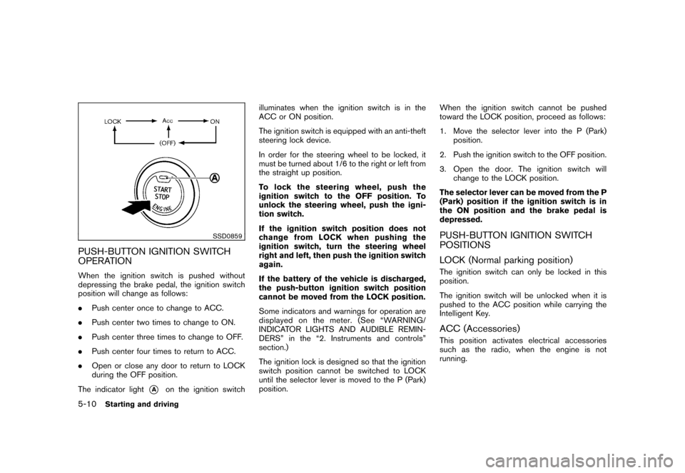
SSD0859
PUSH-BUTTON IGNITION SWITCH
OPERATIONWhen the ignition switch is pushed without
depressing the brake pedal, the ignition switch
position will change as follows:
.Push center once to change to ACC.
. Push center two times to change to ON.
. Push center three times to change to OFF.
. Push center four times to return to ACC.
. Open or close any door to return to LOCK
during the OFF position.
The indicator light
*A
on the ignition switch illuminates when the ignition switch is in the
ACC or ON position.
The ignition switch is equipped with an anti-theft
steering lock device.
In order for the steering wheel to be locked, it
must be turned about 1/6 to the right or left from
the straight up position.
To lock the steering wheel, push the
ignition switch to the OFF position. To
unlock the steering wheel, push the igni-
tion switch.
If the ignition switch position does not
change from LOCK when pushing the
ignition switch, turn the steering wheel
right and left, then push the ignition switch
again.
If the battery of the vehicle is discharged,
the push-button ignition switch position
cannot be moved from the LOCK position.
Some indicators and warnings for operation are
displayed on the meter. (See “WARNING/
INDICATOR LIGHTS AND AUDIBLE REMIN-
DERS” in the “2. Instruments and controls”
section.)
The ignition lock is designed so that the ignition
switch position cannot be switched to LOCK
until the selector lever is moved to the P (Park)
position.
When the ignition switch cannot be pushed
toward the LOCK position, proceed as follows:
1. Move the selector lever into the P (Park)
position.
2. Push the ignition switch to the OFF position.
3. Open the door. The ignition switch will change to the LOCK position.
The selector lever can be moved from the P
(Park) position if the ignition switch is in
the ON position and the brake pedal is
depressed.
PUSH-BUTTON IGNITION SWITCH
POSITIONS
LOCK (Normal parking position)The ignition switch can only be locked in this
position.
The ignition switch will be unlocked when it is
pushed to the ACC position while carrying the
Intelligent Key.ACC (Accessories)This position activates electrical accessories
such as the radio, when the engine is not
running.
5-10
Starting and driving
Page 225 of 329
Black plate (229,1)
Model "Z12-D" EDITED: 2009/ 9/ 17
Turn the wheels toward the side of the road
so the vehicle will move away from the
center of the road if it moves.
4. Models with Intelligent Key system:
Place the ignition switch in the OFF position.
Models without Intelligent Key system:
Place the ignition switch in the LOCK
position and remove the key.
WARNING
.If the engine is not running or is
turned off while driving, the power
assist for the steering will not work.
Steering will be harder to operate.
. When the electric power steering
warning light illuminates with the
engine running, the power assist for
the steering will cease operation.
You will still have control of the
vehicle but the steering will be
harder to operate.
The electric power steering system is designed
to provide power assist while driving to operate
the steering wheel with light force.
When the steering wheel is operated repeatedly
or continuously while parking or driving at a very
low speed, the power assist for the steering
wheel will be reduced. This is to prevent
overheating of the electric power steering
system and protect it from getting damaged.
While the power assist is reduced, steering
wheel operation will become heavy. When the
temperature of the electric power steering
system goes down, the power assist level will
return to normal. Avoid repeating such steering
wheel operations that could cause the electric
power steering system to overheat. You may hear a fricative sound when the
steering wheel is operated quickly. However,
this is not a malfunction.
If the electric power steering warning light
illuminates while the engine is running, it may
indicate the electric power steering system is
not functioning properly and may need servicing.
Have the electric power steering system
checked by a NISSAN dealer. (See “Electric
power steering warning light” in the “2. Instru-
ments and controls” section.)
When the electric power steering warning light
illuminates with the engine running, the power
assist for the steering will cease operation. You
will still have control of the vehicle. However,
greater steering effort is needed, especially in
sharp turns and at low speeds.
ELECTRIC POWER STEERING
SYSTEM
Starting and driving
5-25
Page 233 of 329
Black plate (19,1)
6 In case of emergency
Model "Z12-D" EDITED: 2009/ 9/ 17
Flat tire............................................................ 6-2
Tire Pressure Monitoring System (TPMS) ............. 6-2
Changing a flat tire ......................................... 6-2
Jump starting .................................................... 6-8
Push starting ................................................... 6-10
If your vehicle overheats. .................................... 6-11 Towing your vehicle
.......................................... 6-12
Towing recommended by NISSAN
(except for Kro ¯
m models) ............................... 6-13
Towing recommended by NISSAN
(for Kro ¯
m models) ........................................ 6-14
Vehicle recovery (freeing a stuck vehicle) ........... 6-15
Page 236 of 329
Black plate (240,1)
Model "Z12-D" EDITED: 2009/ 9/ 17
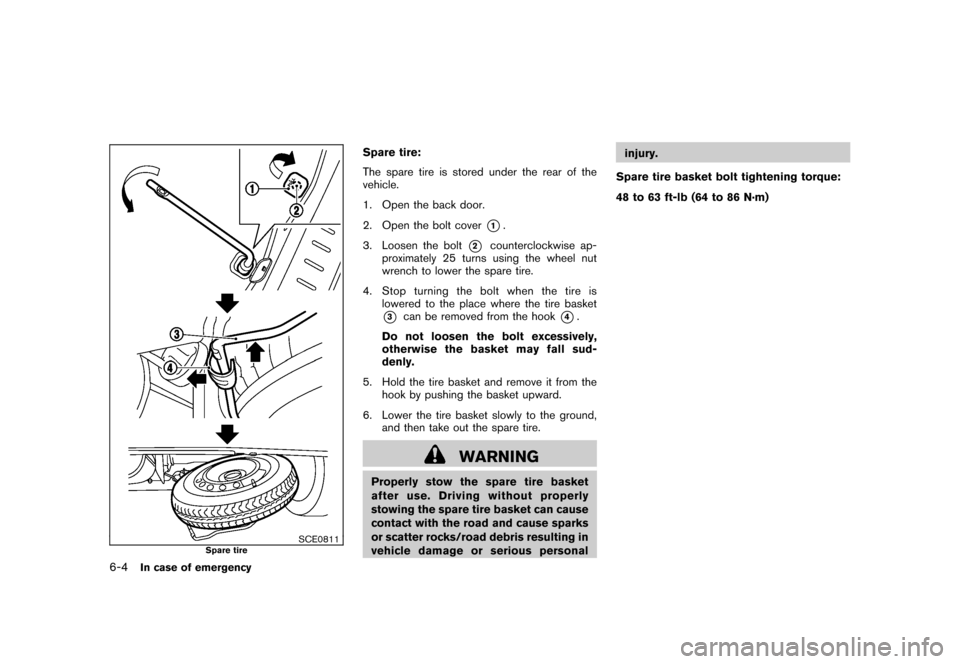
SCE0811
Spare tire
Spare tire:
The spare tire is stored under the rear of the
vehicle.
1. Open the back door.
2. Open the bolt cover
*1.
3. Loosen the bolt
*2
counterclockwise ap-
proximately 25 turns using the wheel nut
wrench to lower the spare tire.
4. Stop turning the bolt when the tire is lowered to the place where the tire basket
*3
can be removed from the hook
*4.
Do not loosen the bolt excessively,
otherwise the basket may fall sud-
denly.
5. Hold the tire basket and remove it from the hook by pushing the basket upward.
6. Lower the tire basket slowly to the ground, and then take out the spare tire.
WARNING
Properly stow the spare tire basket
after use. Driving without properly
stowing the spare tire basket can cause
contact with the road and cause sparks
or scatter rocks/road debris resulting in
vehicle damage or serious personal injury.
Spare tire basket bolt tightening torque:
48 to 63 ft-lb (64 to 86 N·m)
6-4
In case of emergency
Page 239 of 329
Black plate (243,1)
Model "Z12-D" EDITED: 2009/ 9/ 17
SCE0576
Installing the spare tireThe spare tire is designed for emergency
use. (See specific instructions under the
heading “WHEELS AND TIRES” in the “8.
Maintenance and do-it-yourself” section.)
1. Clean any mud or dirt from the surfacebetween the wheel and hub.
2. Carefully put the spare tire on and tighten the wheel nuts finger tight. Check that all the
wheel nuts contact the wheel surface
horizontally.
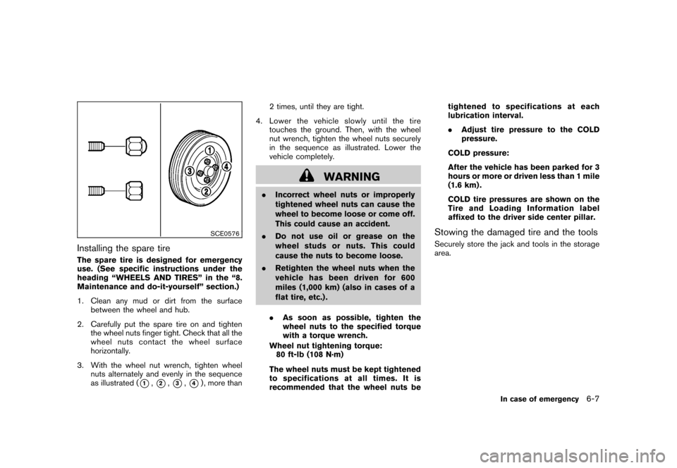
3. With the wheel nut wrench, tighten wheel nuts alternately and evenly in the sequence
as illustrated (
*1,*2,*3,*4) , more than 2 times, until they are tight.
4. Lower the vehicle slowly until the tire touches the ground. Then, with the wheel
nut wrench, tighten the wheel nuts securely
in the sequence as illustrated. Lower the
vehicle completely.
WARNING
.Incorrect wheel nuts or improperly
tightened wheel nuts can cause the
wheel to become loose or come off.
This could cause an accident.
. Do not use oil or grease on the
wheel studs or nuts. This could
cause the nuts to become loose.
. Retighten the wheel nuts when the
vehicle has been driven for 600
miles (1,000 km) (also in cases of a
flat tire, etc.) .
. As soon as possible, tighten the
wheel nuts to the specified torque
with a torque wrench.
Wheel nut tightening torque: 80 ft-lb (108 N·m)
The wheel nuts must be kept tightened
to specifications at all times. It is
recommended that the wheel nuts be tightened to specifications at each
lubrication interval.
.
Adjust tire pressure to the COLD
pressure.
COLD pressure:
After the vehicle has been parked for 3
hours or more or driven less than 1 mile
(1.6 km) .
COLD tire pressures are shown on the
Tire and Loading Information label
affixed to the driver side center pillar.
Stowing the damaged tire and the toolsSecurely store the jack and tools in the storage
area.
In case of emergency
6-7
Page 242 of 329
Black plate (246,1)
Model "Z12-D" EDITED: 2009/ 9/ 17
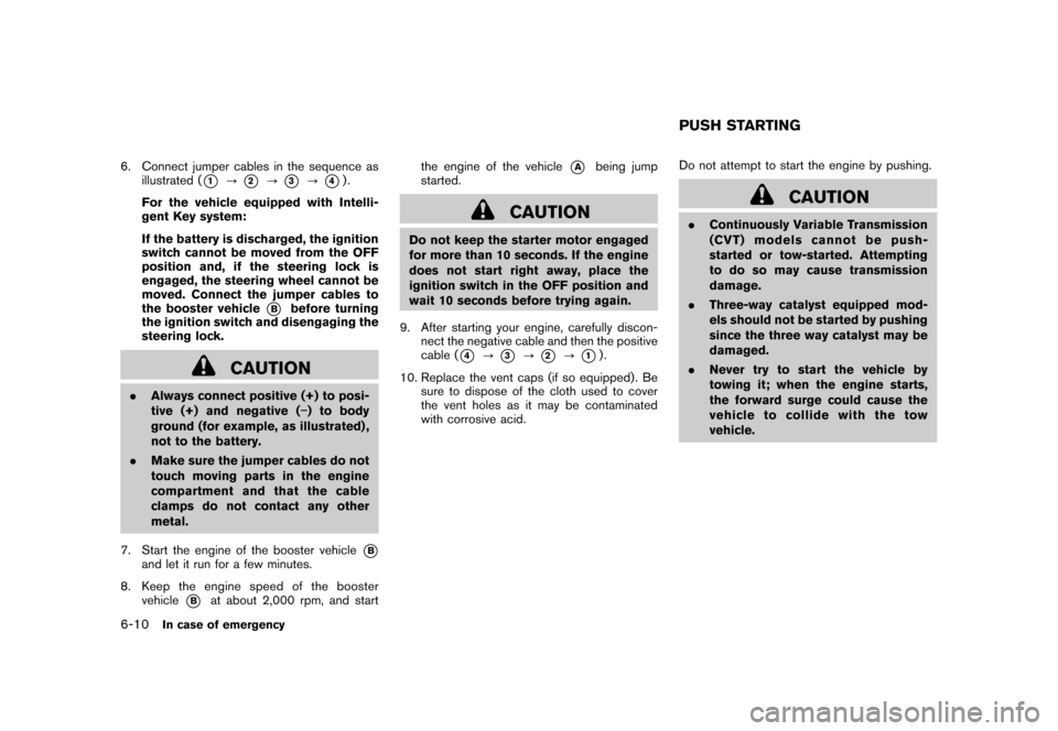
6. Connect jumper cables in the sequence asillustrated (
*1
?
*2
?
*3
?
*4).
For the vehicle equipped with Intelli-
gent Key system:
If the battery is discharged, the ignition
switch cannot be moved from the OFF
position and, if the steering lock is
engaged, the steering wheel cannot be
moved. Connect the jumper cables to
the booster vehicle
*B
before turning
the ignition switch and disengaging the
steering lock.
CAUTION
. Always connect positive (+) to posi-
tive (+) and negative ( �) to body
ground (for example, as illustrated) ,
not to the battery.
. Make sure the jumper cables do not
touch moving parts in the engine
compartment and that the cable
clamps do not contact any other
metal.
7. Start the engine of the booster vehicle
*B
and let it run for a few minutes.
8. Keep the engine speed of the booster vehicle
*B
at about 2,000 rpm, and start the engine of the vehicle
*A
being jump
started.
CAUTION
Do not keep the starter motor engaged
for more than 10 seconds. If the engine
does not start right away, place the
ignition switch in the OFF position and
wait 10 seconds before trying again.
9. After starting your engine, carefully discon- nect the negative cable and then the positive
cable (
*4
?
*3
?
*2
?
*1).
10. Replace the vent caps (if so equipped) . Be sure to dispose of the cloth used to cover
the vent holes as it may be contaminated
with corrosive acid. Do not attempt to start the engine by pushing.
CAUTION
.
Continuously Variable Transmission
(CVT) models cannot be push-
started or tow-started. Attempting
to do so may cause transmission
damage.
. Three-way catalyst equipped mod-
els should not be started by pushing
since the three way catalyst may be
damaged.
. Never try to start the vehicle by
towing it; when the engine starts,
the forward surge could cause the
vehicle to collide with the tow
vehicle.PUSH STARTING
6-10
In case of emergency
Page 244 of 329
Black plate (248,1)
Model "Z12-D" EDITED: 2009/ 9/ 17
When towing your vehicle, all State (Provincial in
Canada) and local regulations for towing must
be followed. Incorrect towing equipment could
damage your vehicle. Towing instructions are
available from a NISSAN dealer. Local service
operators are familiar with the applicable laws
and procedures for towing. To assure proper
towing and to prevent accidental damage to
your vehicle, NISSAN recommends that you
have a service operator tow your vehicle. It is
advisable to have the service operator carefully
read the following precautions.
WARNING
.Never ride in a vehicle that is being
towed.
. Never get under your vehicle after it
has been lifted by a tow truck.
CAUTION
.When towing, make sure that the
transmission, axles, steering system
and powertrain are in working con-
dition. If any unit is damaged, dol-
lies must be used.
. Always attach safety chains before
towing. For information about towing your vehicle behind
a recreational vehicle (RV) , see “FLAT TOW-
ING” in the “9. Technical and consumer
information” section of this manual.TOWING YOUR VEHICLE6-12
In case of emergency
Page 245 of 329
Black plate (249,1)
Model "Z12-D" EDITED: 2009/ 9/ 17
SCE0814
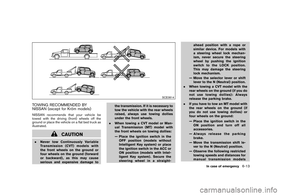
TOWING RECOMMENDED BY
NISSAN (except for Kro¯
m models)NISSAN recommends that your vehicle be
towed with the driving (front) wheels off the
ground or place the vehicle on a flat bed truck as
illustrated.
CAUTION
. Never tow Continuously Variable
Transmission (CVT) models with
the front wheels on the ground or
four wheels on the ground (forward
or backward) , as this may cause
serious and expensive damage to the transmission. If it is necessary to
tow the vehicle with the rear wheels
raised, always use towing dollies
under the front wheels.
. When towing a CVT model or Man-
ual Transmission (MT) model with
the front wheels on towing dollies:
— Place the ignition switch in the
OFF position (models without
Intelligent Key system) or place
the ignition switch in the ACC or
ON position (models with Intel-
ligent Key system) . Secure the
steering wheel in a straight- ahead position with a rope or
similar device. For models with
a steering wheel lock mechan-
ism, never secure the steering
wheel by pushing the ignition
switch to the LOCK position.
This may damage the steering
lock mechanism.
— Move the selector lever or shift lever to the N (Neutral) position.
. When towing a CVT model with the
rear wheels on the ground (if you do
not use towing dollies): Always
release the parking brake.
. If you have to tow an MT model with
the rear wheels on the ground (if
you do not use towing dollies) or
four wheels on the ground:
— Place the ignition switch in the
ON position and turn off all
accessories.
— Always release the parking brake.
— Move the transmission shift le- ver to the N (Neutral) position.
— Observe the following restricted towing speeds and distances for
manual transmission models
In case of emergency
6-13